Language selection

Search

Patent 2161003 Summary

Third-party information liability

Some of the information on this Web page has been provided by external sources. The Government of Canada is not responsible for the accuracy, reliability or currency of the information supplied by external sources. Users wishing to rely upon this information should consult directly with the source of the information. Content provided by external sources is not subject to official languages, privacy and accessibility requirements.

Claims and Abstract availability

Any discrepancies in the text and image of the Claims and Abstract are due to differing posting times. Text of the Claims and Abstract are posted:

  • At the time the application is open to public inspection;
  • At the time of issue of the patent (grant).
(12) Patent: (11) CA 2161003
(54) English Title: ARMREST DEVICE FOR A CHAIR
(54) French Title: APPUI-BRAS POUR SIEGE
Status: Expired and beyond the Period of Reversal
Bibliographic Data
(51) International Patent Classification (IPC):
  • A47C 07/54 (2006.01)
(72) Inventors :
  • HOLSTENSSON, LARS (Sweden)
(73) Owners :
  • ERGONOMIPRODUKTER I BODAFORS AB
(71) Applicants :
  • ERGONOMIPRODUKTER I BODAFORS AB (Sweden)
(74) Agent: GOWLING WLG (CANADA) LLP
(74) Associate agent:
(45) Issued: 2004-09-14
(86) PCT Filing Date: 1994-04-14
(87) Open to Public Inspection: 1994-10-27
Examination requested: 2001-02-21
Availability of licence: N/A
Dedicated to the Public: N/A
(25) Language of filing: English

Patent Cooperation Treaty (PCT): Yes
(86) PCT Filing Number: PCT/SE1994/000329
(87) International Publication Number: SE1994000329
(85) National Entry: 1995-10-19

(30) Application Priority Data:
Application No. Country/Territory Date
9301286-2 (Sweden) 1993-04-20

Abstracts

English Abstract


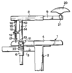
An armrest device for an office chair
compares a fastening element (6) intended to be fixed
to the chair beside the seat (4). The device
further includes an armrest (7, 8, 9, 20) which is
connected to the fastening element (6) and has a
vertical column (7) so connected to the fastening
element as to be rotatable about its longitudinal
axis, a horizontal rear, supporting bar (8)
connectedto the column, and a front supporting bar (9)
carrying a forearm rest (20), on which the user's
forearm is to rest, and being telescopically
displaceable in relation to the rear supporting bar
(8) in order to form an armrest that can be
lengthened and shortened as desired. The rear
supporting bar (8) is so mounted on the column (7) as
to be pivotable about a horizontal transverse axis
(10). A spring means (15, 16, 17, 18, 19) is
arranged to maintain the tear supporting bar (8)
in an initial position and to counteract, with an
adjustable spring pressure, pivotal movement of
the rear supporting bar (8) about the horizontal
transverse axis (10) caused by a depression of
the forearm rest (20).


Claims

Note: Claims are shown in the official language in which they were submitted.


7
CLAIMS
1. An armrest device for a chair, especially an
office chair, said device comprising a fastening element
(5, 6), which is adapted to be fixed to the chair beside
the seat (4) thereof, and an armrest (7, 8, 9, 20), which
is connected to the fastening element and has a substan-
tially vertical column (7) so connected to the fastening
element as to be rotatable about its longitudinal axis, a
substantially horizontal rear supporting bar (8) con-
nected to the column, and a front supporting bar (9)
carrying a forearm rest (20), on which the user's forearm
is to rest, and being telescopically displaceable in
relation to the rear supporting bar (8) in order to form
an armrest that can be lengthened and shortened as
desired, characterised in that the rear
supporting bar (8) is so mounted on the column (7) as to
be pivotable about a substantially horizontal transverse
axis (10), and that a spring means (15, 16, 17, 18, 19)
is adapted to maintain the rear supporting bar (8) in an
initial position as regards its pivotal movement about
the horizontal transverse axis (10) and to counteract,
with an adjustable spring pressure, pivotal movement of
the rear supporting bar (8) from this initial position
caused by a depression of the forearm rest (20), said
spring means (15, 16, 17, 18, 19) comprising a threaded
rod (15) which is articulated to the rear supporting bar
(8) and extends through a part (14) fixedly connected to
the column (7), a spring (19) arranged on the rod (15)
between said part (14) and an adjusting nut (17) screwed
on the rod (15) for adjusting the pressure exerted by the
spring (19), and a stop nut (18) screwed on the rod (15)
for setting the initial position.
2. An armrest device as claimed in claim 1,
characterised in that a spring (22) is
arranged between the armrest (7, 8, 9, 20) and the

8
fastening element (5, 6) to return the column (7) to a
preset initial position after it has been rotated about
its longitudinal axis from this position.

Description

Note: Descriptions are shown in the official language in which they were submitted.


WO 94/23616 ~ ~ PCTlSE94/00329
1
ARMREST DEVICE FOR A CHAIR
This invention relates to an armrest device for a
chair, especially an office chair, the device comprising
a fastening element adapted to be fixed to the chair
beside the seat thereof, as well as an armrest connected
to the fastening element.
In a prior-art armrest device of this type, the arm-
rest has a horizontal rear supporting bar, which is so
connected to the fastening element as to be pivotable
about a vertical axis, and a horizontal front supporting
bar, which is movably connected to the rear supporting
bar and carries a forearm rest, on which the user's fore-
arm is to rest. The rear end of the front supporting bar
is articulated to the front end of the rear supporting
bar, so that the two supporting bars are pivotable in
relation to one another about a vertical axis. The fore-
arm rest, which is provided at the front end of the front
supporting bar, is tiltable about an axis that extends
transversely of the front supporting bar and pivotable
about a vertical axis. One armrest device is to be
mounted on each side of the chair.
This known armrest device has been developed for the
specific purpose of eliminating the shoulder and back-of-
the-head strains from which office employees spending
most of their time in front of a typewriter, a word
processor, a computer or the like often suffer and which,
in many cases, cause severe pain. Although the known arm-
rest device has proved successful in this respect, it is
a somewhat complicated, and hence expensive, device.
Furthermore, this device is disadvantageous by requiring
a considerable operating space on the side of the chair
where the armrest device is mounted.
There is, however, a simple and inexpensive armrest
device which does not suffer from this drawback. Like the

~~o~oo
WO 94/23616 PCT/SE94/00329
2
armrest device described in the foregoing, this other
device comprises an armrest that has a horizontal rear
supporting bar, which is so connected to the fastening
element as to be rotatable about a vertical axis, and a
horizontal front supporting bar, which is movably con-
nected to the rear supporting bar and carries a forearm
rest, on which the user's forearm is to rest. The two
supporting bars are telescopically displaceable in rela-
tion to one another in order to form an armrest that can
be lengthened and shortened as desired, for which reason
this armrest device requires less space.
The object of the present invention is to improve
the last-mentioned armrest device, such that it can be
adjusted to meet the needs of different users, thus
offering each particular user optimum working conditions
in respect of strain.
According to the invention, this object is achieved
by an armrest device for a chair, especially an office
chair, said device comprising a fastening element, which
is adapted to be fixed to the chair beside the seat
thereof, and an armrest, which is connected to the
fastening element and has a substantially vertical column
so connected to the fastening element as to be rotatable
about its longitudinal axis, a substantially horizontal
rear supporting bar connected to the column, and a front
supporting bar carrying a forearm rest, on which the
user's forearm is to rest, and being telescopically dis-
placeable in relation to the rear supporting bar in order
to form an armrest that can be lengthened and shortened
as desired, said device being characterised in that the
rear supporting bar is so mounted on the column as to be
pivotable about a substantially horizontal transverse
axis, and that a spring means is adapted to maintain the
rear supporting bar in an initial position as regards its
pivotal movement about the horizontal transverse axis and
to counteract, with an adjustable spring pressure,
pivotal movement of the rear supporting bar from this

PCT/SE94/00329
WO 94/23616
3
initial position caused by a depression of the forearm
rest, said spring means comprising a threaded rod which
is articulated to the rear supporting bar and extends
through a part fixedly connected to the column, a spring
arranged on the rod between said part and an adjusting
nut screwed on the rod for adjusting the pressure exerted
by the spring, and a stop nut screwed on the rod for set-
ting the initial position.
In a preferred embodiment, a spring is arranged bet-
ween the armrest and the fastening element to return the
column to a preset initial position after it has been
rotated about its longitudinal axis from this position.
The invention will now be described in more detail
with reference to the accompanying drawing, in which
Fig. 1 is a top view of an armrest device according
to the invention, and
Fig. 2 is a side view of the armrest device.
In the drawing, the armrest device according to the
invention is mounted on an office chair 1 (only schemati-
cally shown). The office chair 1 has a base column 2 sup-
porting a frame 3, which carries the seat 4 and the back
(not shown) of the chair. On both sides of the office
chair 1, the frame 3 has a horizontal tubular frame ele-
ment (not shown) which is located on a level with the
rear portion of the seat 4 and extends in the transverse
direction of the chair. The office chair 1 is provided
with an armrest device on each side. For reasons of
clarity, however, only the right-hand armrest device is
shown in the drawing.
In the description, as well as in the appended
claims and abstract, the words "horizontal", "vertical",
' "front" and "rear" relate to the position of the armrest
device when mounted on the office chair 1.
The armrest device has a fastening element which
consists of a horizontal bar 5 and a vertical sleeve 6
arranged at one end thereof. The fastening element 5, 6
is mounted on the frame 3 of the office chair 1 by the

2~6~4~~
WO 94/23616 PCTlSE94/00329
4
bar 5 being introduced a certain distance into the tubu-
lar element of the frame 3 and fixed in the desired posi-
tion therein by means of a locking screw (not shown).
Furthermore, the armrest device includes an armrest
which consists of a vertical column 7, a horizontal rear
supporting bar 8 pivotably connected to the column 7, and
a horizontal front supporting bar 9 movably connected to
the rear supporting bar 8. The rear supporting bar 8 is
connected to the column 7 by a transverse horizontal
pivot pin 10, about which it pivots in relation to the
column. The column 7 is rotatably mounted in the sleeve
6, and its vertical position therein can be adjusted by
means of a locking ring 11 which is displaceable along
the column and can be fixed in the desired position by
means of a locking screw 12 with a knob-shaped head 13.
Thus, the armrest device is pivotable about the axis
defined by the sleeve 6.
The column 7 has a rear projection 14. A rod 15,
which is articulated to the rear supporting bar 8 by a
pin 16 parallel to the pivot pin 10, extends displaceably
through a hole in the projection 14. The rod 15 is
threaded along the major part of its length. An adjusting
nut 17 is screwed on the bottom portion of the rod 15,
and a stop nut 18 is screwed on the top portion thereof.
A compression spring 19 is passed onto the rod 15 and
abuts against the projection 14 at its top end and
against the adjusting nut 17 at its bottom end. The
spring pressure is adjusted with the aid of the adjusting
nut 17. The spring 19 strives to pull the rod 15 down-
wards, thereby to pivot the rear supporting bar 8 anti-
clockwise, as seen in Fig. 2. The end position is defined
by the stop nut 18.
The rear supporting bar 8 is made up of a tube to
which the front supporting bar 9 is telescopically con-
nected. Conveniently, the front supporting bar 9 is made
up of a fixed guide member, which with a close fit is
inserted into the tube 8, and a movable guide member,

PCT/SE94/00329
WO 94/23616
which is easily displaceable in relation to the fixed
guide member. Conveniently, such a supporting bar is a
device of the type marketed by Hettich Skandinaviska AB
under the trade name Expansion KA 270/350. The fixed
5 guide member is sluggishly rotatable in the tube 8 to
enable setting of the desired rotational position of the
front supporting bar 9.
At the front end, the front supporting bar 9 carries
a bowl-shaped forearm rest 20, on which the user's fore-
arm is to rest. The forearm rest 20 is made of soft poly-
urethane. A U-shaped element 21, which is turned upside-
down, is welded over the front supporting bar 9. A sleeve
(not shown), which opens at the underside of the forearm
rest 20, is embedded in the polyuretha:.e material. The
web of the U-shaped element 21 has an upwardly-directed
pin (not shown) extending into the sleeve. As a result,
the forearm rest 20 is rotatable about the pin.
With the aid of the stop nut 18, the user of the
armrest device sets a suitable initial position for the
armrest (normally the position shown in Fig. 2, in which
the supporting bars 8 and 9 are horizontal) and sets,
with the aid of the adjusting nut 17, a suitable pressure
for the spring 19. This spring pressure, which determines
the pressure required for pivoting the rear supporting
bar 8 clockwise (as seen in Fig. 2) about the pivot pin
10, is set at a value suitable for the user.
A helical spring 22 is arranged round the sleeve 6.
One end of the helical spring 22 engages the locking
screw 12, and the other end of the spring engages the
horizontal bar 5. The helical spring 22 is so arranged
that it strives by exerting a slight force to maintain
' the armrest in such a rotational position that the sup
porting bars 8 and 9 are directed straight forwards, as
' shown in Fig. 1. If the user swings the armrest outwards
or inwards from this position, e.g. when he or she gets
out of the chair 1, and then lets go of the armrest, the
latter will be returned to the position shown in Fig. 1

WO 94/23616 PCTISE94100329
6
by the helical spring 22. Another reference rotational
position than the one shown in Fig. 1 may, if so desired,
be obtained simply by loosening the locking screw 12 and
turning the armrest slightly in relation to the locking
ring 11, whereupon the looking screw 12 again is tighten-
ed.
The armrest device described above is of simple con-
struction. Because the front supporting bar 9 travels
readily in the rear supporting bar 8 and the column 7 is
easily rotated in the sleeve 6, the user may, with his or
her forearm resting on the forearm rest 20, expediently
set the device in the desired position and just as easily
adjust the set position when so required. Moreover, the
armrest device is easily adapted to meet the needs of
different users as regards the vertical resilience
produced by the spring 19. As a result of the inventive
arrangement, the armrest device offers the user a most
favourable working posture in respect of strain.

Representative Drawing
A single figure which represents the drawing illustrating the invention.
Administrative Status

2024-08-01:As part of the Next Generation Patents (NGP) transition, the Canadian Patents Database (CPD) now contains a more detailed Event History, which replicates the Event Log of our new back-office solution.

Please note that "Inactive:" events refers to events no longer in use in our new back-office solution.

For a clearer understanding of the status of the application/patent presented on this page, the site Disclaimer , as well as the definitions for Patent , Event History , Maintenance Fee  and Payment History  should be consulted.

Event History

Description Date
Time Limit for Reversal Expired 2011-04-14
Letter Sent 2010-04-14
Grant by Issuance 2004-09-14
Inactive: Cover page published 2004-09-13
Inactive: Final fee received 2004-07-05
Pre-grant 2004-07-05
Notice of Allowance is Issued 2004-04-16
Letter Sent 2004-04-16
Notice of Allowance is Issued 2004-04-16
Inactive: Approved for allowance (AFA) 2004-03-08
Amendment Received - Voluntary Amendment 2001-04-04
Letter Sent 2001-03-13
Inactive: Status info is complete as of Log entry date 2001-03-13
Inactive: Application prosecuted on TS as of Log entry date 2001-03-13
All Requirements for Examination Determined Compliant 2001-02-21
Request for Examination Requirements Determined Compliant 2001-02-21
Deemed Abandoned - Failure to Respond to Maintenance Fee Notice 1997-04-14
Inactive: Adhoc Request Documented 1997-04-14
Application Published (Open to Public Inspection) 1994-10-27

Abandonment History

Abandonment Date Reason Reinstatement Date
1997-04-14

Maintenance Fee

The last payment was received on 2004-03-17

Note : If the full payment has not been received on or before the date indicated, a further fee may be required which may be one of the following

  • the reinstatement fee;
  • the late payment fee; or
  • additional fee to reverse deemed expiry.

Patent fees are adjusted on the 1st of January every year. The amounts above are the current amounts if received by December 31 of the current year.
Please refer to the CIPO Patent Fees web page to see all current fee amounts.

Owners on Record

Note: Records showing the ownership history in alphabetical order.

Current Owners on Record
ERGONOMIPRODUKTER I BODAFORS AB
Past Owners on Record
LARS HOLSTENSSON
Past Owners that do not appear in the "Owners on Record" listing will appear in other documentation within the application.
Documents

To view selected files, please enter reCAPTCHA code :


To view images, click a link in the Document Description column (Temporarily unavailable). To download the documents, select one or more checkboxes in the first column and then click the "Download Selected in PDF format (Zip Archive)" or the "Download Selected as Single PDF" button.

List of published and non-published patent-specific documents on the CPD .

If you have any difficulty accessing content, you can call the Client Service Centre at 1-866-997-1936 or send them an e-mail at CIPO Client Service Centre.

({010=All Documents, 020=As Filed, 030=As Open to Public Inspection, 040=At Issuance, 050=Examination, 060=Incoming Correspondence, 070=Miscellaneous, 080=Outgoing Correspondence, 090=Payment})


Document
Description 
Date
(yyyy-mm-dd) 
Number of pages   Size of Image (KB) 
Representative drawing 1998-06-29 1 8
Abstract 1994-10-26 1 54
Description 1994-10-26 6 265
Claims 1994-10-26 2 51
Drawings 1994-10-26 1 18
Representative drawing 2004-03-07 1 7
Reminder - Request for Examination 2000-12-17 1 119
Acknowledgement of Request for Examination 2001-03-12 1 179
Commissioner's Notice - Application Found Allowable 2004-04-15 1 161
Maintenance Fee Notice 2010-05-25 1 171
PCT 1995-10-18 7 290
Correspondence 1997-04-02 1 26
Fees 2003-03-18 1 32
Fees 1998-03-22 1 37
Fees 2002-03-18 1 34
Fees 2001-03-19 1 30
Fees 1999-03-24 1 32
Fees 2000-03-19 1 30
Fees 2004-03-16 1 31
Correspondence 2004-07-04 1 32
Fees 1997-04-07 1 30