Note: Descriptions are shown in the official language in which they were submitted.
2161031
1 --
KNIFE AND METHOD FOR MANUFACTURING A KNIFE
The invention relates to a method for manufacturing
flame-spray coated knives, knife blades or the like, and a knife, knife
blade or the like of this kind according to the preamble of Claim 1 or
Claim 17 respectively.
A'knife of this kind and a method for manufacturing such a
knife is known from U.S. Patent Specification No. 3,732,771. In this,
the blade body, which consists of hard steel, of a knife blade is to be
provided on one side with a coating of hard material. In this, there
is proposed as coating, inter alia, a flame-sprayed chromium coating.
The coating is to be harder than the material of the steel knife
body. The United States patent specification starts from the idea
that a knife blade thus coated may have material removed from the
uncoated side in such a way that a cutting edge is formed by an edge of
the coating. In the normal scale representation in the relevant state
of the art, the ground surface section of the coating is to be adjacent
to a ground surface section of the steel region. It has been shown in
2161031
-- 2 --
practice that for knife blades, which have been manufactured according
to the method there disclosed, the cutting edge formation is not of
this kind on the microscopic scale. Seen on the microscopic scale,
the ground surface section does not connect in a step-free manner with
the ground steel surface section, and in particular does not therefore
connect with this section in an aligned manner.
In the case of the method according to German Patent
Specification No. 3700250, there is again present at the microscopic
level a structure other than that described in the descriptive text.
This differently formed structure, which results from the coating
breaking away at the tip during the removal of material from the
coating-free wide side surface, has the consequence that the
self-sharpening effect desired in the descriptions of the
initially-mentioned documents does not occur. The cutting function
takes place in the knives described according to the state of the art
not at the edge of the coating but at the step in the blade body in the
region of the boundary layer between coating and substrate.
It is an object of the invention to overcome this disadvantage
of the state of the art by forming the cutting edge connection of the
coating to the substrate at the microscopic level in such a manner that
the actual cutting operation is not effected by the steel blade body.
This object is met by the knife recited in Claim 1 and by the
method recited in Claim 17.
The subsidiary claims represent advantageous further
embodiments of the invention.
As a result of the embodiment according to the invention, it
is achieved that at the microscopic level also, the boundary surface
between the coating and the substrate no longer makes any contribution
to the cutting function. It is by contrast brought about that only
the cutting edge, which is formed by an edge of the coating, carries
out the cutting function. Since in the cutting action, the weaker
2161031
blade body is subjected to stronger friction than the harder coating
and the coating has been applied to the substrate without breaking
away, no second cutting edge is formed even with continuous use, which
will be formed with steel. It is by contrast achieved that the
coating merges in a step-free manner into the steel region, and this
microscopic structure remains retained even after quite a long period
of time. As a result, there is provided a substantial improvement in
the cutting capability compared with a knife according to the state of
the art. In cutting tests with standardised abrasive material, it has
been shown that knives according to the invention, even after a cutting
depth which corresponds to a height of cut material of 23 metres, still
have a sharpness which is no longer achieved by comparable ceramic
knives even after only some hundreds of millimetres. The
self-sharpening effect claimed in the state of the art as an objective
actually occurs for knives according to the invention. Compared with
customary coated steel knives, the improvement in cutting capability is
more evident. While conventional coated steel knives were already
blunt after a cutting depth of 130 mm during tests, for knives
according to the invention, the flattening of the coating at the
cutting edge had stabilised in the region of 1 to 3 um. The knife
remained sharp to the same extent. In a preferred embodiment of a
knife according to the invention, in which the ground surface section
of the coating, which connects in a step-free manner with the ground
steel surface section of the blade body, has a lower peak to valley
roughness dimension than the wide side surface of the coating, a
further improved cutting capability is achieved. It may further be
provided that the peak to valley roughness dimension of the ground
surface section is substantially identical to the peak to valley
roughness dimension of the ground surface section of the steel knife
body. The peak to valley roughness dimension of the wide side surface
of the coating may amount to approximately 10 um or less. The peak to
valley roughness dimension of the ground surface section may amount to
approximately 5 um or less. It has been shown that in the flame-spray
coating, the steel knife body is heated up. This temperature
elevation in the region of the coated surface leads to a tempering
2161031
and a reduction in hardness in the region of the boundary layer. In
the state of the art, the tempered zone has a very great thickness, so
that the retention of the coating on the knife body is not optimal,
with the result noted initially, that the coating breaks away. It is
now provided according to the invention that the tempered zone has a
minimised thickness. The thickness of the tempered zone should to
this end preferably be less than the thickness of the coating and
preferably less than 5 or 10 um. As a result of this embodiment, the
core of the knife body is not influenced by the flame-spraying in
respect of its hardness. Only in a very thin zone in the region of
the boundary surface, which preferably is formed to be so thin that it
is no longer apparent, is the knife body tempered and has a reduced
hardness. The thickness of the coating is preferably between 10 and
60 um, depending on the material used for the coating. It has been
found that an optimal coating thickness amounts to approximately 30 to
40 um. By this thickness of coating, there is on the one hand formed
a sufficiently larger grindable surface region of the coating and on
the other hand, the coating is sufficiently thin as not to break
away. It may be further provided that the thickness of the tempered
zone extends in a homogeneous manner over the entire coated wide side
surface, having therefore substantially a uniform thickness. The
coating may consist of a hard carrier material, in which particles of
hard material are embedded. The thickness of the tempered zone should
be at a maximum ten times as great as the thickness of the particles of
hard material. By selection of these sizes, it is assured that in the
coating, the particles of hard material burying themselves in the
surface enter into an optimal retention with the weaker knife body
zone. The particles of hard material may consist of tungsten carbide
and the carrier material may consist of cobalt. The particles of hard
material and the carrier material may be formulated in a ratio of 80:20
to 90:10. A ratio of 88:12 is preferred. In an embodiment which is
not at present preferred, there may be provided, in addition to a first
component consisting of tungsten carbide/cobalt, a second component for
the coating which has in particular, nickel, chromium, boron and/or
silicon. The second component should then amount to less than 50%,
2161031
preferably 30%, of the coating composition. The hardness of the
coating is preferably far above the hardness of the blade body. For a
coating with tungsten carbide grains, according to the literature, a
hardness of 1800 HV 0.3 is prescribed. This hardness is to be
compared with a hardness for the knife body of approximately 650 HV
0.3. The hardness of the tempered zone is less than the hardness of
the blade body and may amount to approximately 550 HV 0.3.
The method according to the invention for manufacturing a
knife blade provides that a coating of hard material is flame-sprayed
on at high speed on one side of the hardened basic blade body, and that
subsequently the blade is ground on the other side. To this end, it
is provided that the surface region to be coated is bombarded with an
abrasive granulate before the coating with hard material. In this
manner, the peak to valley roughness dimension of the surface to be
coated is to be changed. The bombardment with the granulate is to be
effected in such a manner that the tip region of the blade body is bent
sideways as a result of the bombardment pressure. In section through
a bombarded blade body, a nose which is bent sideways is then formed at
the cutting edge. This nose is also sprayed in the subsequent
flame-spray coating and is then ground away. Preferably the coating
with hard material is carried out at supersonic speed. The
powder-form coating material entrained in the flame is to be heated up
in the flame to approximately 2000 to 3000C. In order to avoid
that the wide side surface of the blade body is heated up to an
impermissible level during the flame-spray coating, it is provided that
the blade is coated in several successive steps, each consisting of a
thin partial coating. The surface has therefore the opportunity to
cool down again between the application of the individual partial
layers. In addition, less heat requires to be conducted away on
account of the lesser amount of material applied in each case in the
individual partial steps. ~uring the coating, the surface of the
blade body should preferably be heated up for a short period only to
400C at a maximum. The opposite side should thereby reach 80 at
a maximum. Only in the region of the tip zone, which is later ground
~ 2161031
away, is a higher temperature permissible. In this process, the
weaker tempered zone is reduced to a minimum which is no longer
detectable. The grinding of the blade should preferably be carried
out in several successive steps. There is preferably achieved in the
first grinding step, the removal of the tip zone already mentioned.
In this, there must be accepted a breaking away of the coating in this
region. In one or several second material removal steps, the blade
body and the coating may then be ground to such an extent that the
ground surface regions of blade body and coating x are aligned with one
another. The heat impact during the high speed flame-spraying is so
selected in combination with the impact time that no localised
corrosion or pitting occurs either at the cutting edge or on the wide
side surface in use of the finished knife. The coating parameters are
preferably so selected that the thermal loading on the blade body does
not lead to any damaging stresses in the blade body.
An embodiment of the invention is described below having
regard to the accompanying drawings.
Figure 1 shows a knife according to the invention in front
view,
Figure 2 is a section on the line II-II of Figure 1,
Figure 3 shows the microscopic representation of the cutting
edge region of a knife manufactured by a process according to the state
of the art,
Figure 4 shows the microscopic representation of the cutting
edge region of a non-bombarded/non-coated blade body in the region of
the cutting edge,
Figure 5 is a representation according to Figure 4 after the
bombardment,
2161031
Figure 6 is a representation following on Figure 5 and in
accordance with Figure 5, following the coating,
Figure 7 is a representation following on Figure 6, after the
first removal of material,
Figure 8 is an enlarged representation following on Figure 7,
after the final removal of material,
Figure 9 is an enlarged representation of the cutting edge
region of a knife according to the invention,
Figure 10 is an enlarged representation of the coated
intermediate product before the first removal of material, and
Figure 11 is a schematic representation of the progression of
the hardness along the line XI-XI in Figure 9.
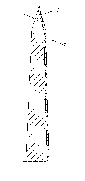
The starting point of the invention is shown in Figure 3.
There is there in question a section through the cutting edge region of
a blade, which has been coated according to the state of the art
initially identified. There is formed in the case of this knife an
edge (projection U), which is defined by two surfaces of the coating,
but this edge is not the cutting edge. The cutting edge is formed by
the steel backing material 1 and moreover by a projection bordered by
the broad side surface 2 to be coated. In the microscopic
representation shown in Figure 3, it is apparent that the retention of
the coating 3 on the boundary layer 2 is only insufficient. In the
cutting process, the end face of the coating is not abraded away.
There break away rather fragments of the coating from the boundary
layer 2, so that in the cutting region, the coating has no significance.
The knife according to the invention has a blade body 1, which
consists of hardened steel. According to Figure 4, the blank to be
coated is ground to a cutting edge. By this there results a sharpened
21 6I D31
tip region 11 for a cutting edge, which separates the two opposed wide
side surfaces 2 and 4. The two wide side surfaces 2 and 4 meet one
another in the tip region 11 at a sharp angle.
After manufacture of the blank according to Figure 4, the
blank is bombarded with granulate in the cutting edge region of one
wide side surface 2. The particles of granulate are fine-grained and
abrasive. The wide side surface 2 is roughened by this bombardment.
The bombardment is effected with an intensity and for a duration such
that the tip region 11 is bent around in the direction turned away from
the steel. In sectionr there results thereby a nose-shaped bent
portion ~see Figure 5).
In a subsequent process step, the bombarded wide side surface
2 is provided with a coating of hard material. The hard material
consists of tungsten carbide particles of approximately 1 um
diameter. The tungsten carbide particles are embedded in a cobalt
matrix. The coating is effected by the flame spray process. To this
end, the coating material is put in powder form into a flame and heated
up to approximately 2000 to 3000C by means of the flame. The mass
thus heated up is then applied at very high speed, in fact at a
supersonic speed, onto the substrate formed by the wide side surface 2
of the blade body 1.
A very thin first layer is initially applied, in which the
particles of hard material are also embedded into the treated surface
of the wide side surface 2 and are anchored therein. The thin coat
application results therefore in the spray coating with corresponding
speed the wide side surface 2. The speed and the spray intensity are
selected so that the surface of the wide side surface is heated up to
at most 400C during this coating, to a temperature therefore at
which no damaging softening of the material takes place. In further
coating steps, a multiplicity of thin layers are successively applied,
until the required thickness of the coating 3 is achieved.
2161031
The coating material consists of a mixture of tungsten carbide
particles and cobalt in a mixture ratio of 88 to 12. The coating then
also consists of exactly this ratio. The coating 3 extends over the
cutting edge end section of the wide side surface 2 up to over the
central plane of the cutting edge region of the blade body and beyond
it in a direction towards the uncoated wide side surface, since the tip
region 11 is bent in the direction of the lee side. It is permissible
for the tip region 11 to be heated up during the coating to a higher
temperature than the remainder of the wide side surface 2 to be
coated. The temperature to which the tip region 11 is heated may
therefore be so great that the entire tip region experiences a
softening of the material.
In the method step illustrated in Figure 7, the cutting edge
is in a first material removal step ground from the uncoated side 4.
The removal of material is achieved by a grindstone, which is
rotated. In the method step shown in Figure 7, the entire tip region
11 is taken away. In this, it must be accepted that a partial region
of the coating 2 is broken off at the boundary surface between coating
and substrate. By this, a projection 12 is formed. This projection
12 is taken away again in subsequent material removal steps (see Figure
8) until the ground surface A consists of two surface sections 6 and 7
which are aligned with one another, the surface section 6 being
associated with the layer 3 and surface section 7 with the steel blade
body 1. During the removal of material, the ground surface is made
smooth, so that the surface section 6 has a smaller peak to valley
roughness dimension than the surface section 8, which is provided by
the flame coating. The cutting edge is formed by the edge 5. The
surface sections 6 and 8 thus meet one another at an angle of
preferably 22 to 24. In Figure 9, the actual structure achieved
for the cutting edge section is shown. The surface sections 6 and 7
merge into one another in a step-free manner and have the same
roughness (peak to valley height), which is less than the peak to
valley height of the surface 8. The thickness D amounts in the
embodiment to less than 1 um and is therefore shown in the drawings to
2161031
- 10 -
a disproportionately large scale. The thickness S of the layer of
hard material amounts to 30 um.
The ground surface A results in a sharp angle (22 to 24)
towards the uncoated wide side, so that a cutting edge 5 is formed with
a less acute angle than the tip angle of the tip 11 of the blank
(Figure 4). The length of the steel section removed is about four
times longer than the length of the section 6. In the case of a
typical coating thickness of approximately 30 um, there thus results a
ground surface A in which the coating sections 6 and 7 merge
microscopically in aligned manner into one another, so that it is
assured that the cutting edge is formed by the edge 5 of the coating.
Depending on the hardness of the coating material, the selection of the
coating thickness is effected so that this is not broken off by correct
use of the knife. The thickness of the starting zone has importance
as a further parameter; its thickness is chosen so that an optimal
anchoring of the coating is achieved by the tungsten carbide particles
entering into the surface 2 of the steel body.
The run or variation of the hardness in the cutting edge
section is shown in Figure 11. The coating 3 has throughout its
thickness S a substantially constant hardness, namely approximately
1800 HV 0.3. In the region of the boundary surface, the hardness
reduces abruptly to a value which amounts to approximately 550 HV
0.3. This value is associated with the tempered zone 9. Across the
thickness D of the tempered zone 9, the hardness increases continuously
with greater depth T up to the hardness of the bulk material of the
blade body 1. Here the hardness is 650 HV 0.3.
As may be seen from Figure 10, the thickness of the tempered
zone 9 is constantly thick over the entire extent of the cross-section
of the layer 3. In Figure 10, the thickness is shown to an enlarged
scale. In ideal conditions, it is substantially less than 1 um, not
therefore to-be checked by etching or the like. The end of the
boundary layer 9 is represented by the broken line. In the region of
` 2l6Io3l
the tip zone 11, a greater thickness of the tempered zone 9 is
permissible. In the exemplary embodiment, the entire tip 11 is
associated with the tempered zone 9. It is however provided that this
section, in which the tempered zone is thicker than in the remainder of
S the coated section, is subsequently taken away. In the region 14 of
the layer 3 remote from the cutting edge, the layer continuously tapers
off. The boundary (broken line) of the tempered zone 9 here runs into
the wide side surface, so that a tempered outer surface region 13
results, the extent of which corresponds to the thickness D of the
tempered zone 9.
All features disclosed are inventive. In the publication of
the application, there is in this regard also to be taken into account
as to their complete content, the disclosure content of the
associated/accompanying priority documents (copy of the earlier
application), also to this end, features of these documents are to be
incorporated in the claims of the present application.