Language selection

Search

Patent 2161129 Summary

Third-party information liability

Some of the information on this Web page has been provided by external sources. The Government of Canada is not responsible for the accuracy, reliability or currency of the information supplied by external sources. Users wishing to rely upon this information should consult directly with the source of the information. Content provided by external sources is not subject to official languages, privacy and accessibility requirements.

Claims and Abstract availability

Any discrepancies in the text and image of the Claims and Abstract are due to differing posting times. Text of the Claims and Abstract are posted:

  • At the time the application is open to public inspection;
  • At the time of issue of the patent (grant).
(12) Patent: (11) CA 2161129
(54) English Title: ROCK DRILL PERCUSSION MECHANISM
(54) French Title: MECANISME POUR OUTIL DE FORAGE A PERCUSSION
Status: Expired and beyond the Period of Reversal
Bibliographic Data
(51) International Patent Classification (IPC):
  • B25D 9/14 (2006.01)
  • B25D 9/12 (2006.01)
  • B25D 9/20 (2006.01)
(72) Inventors :
  • LEPPANEN, JARMO UOLEVI (South Africa)
  • BRIGGS, ROGER ROBARTS (United Kingdom)
(73) Owners :
  • JARMO UOLEVI LEPPANEN
  • ROGER ROBARTS BRIGGS
(71) Applicants :
(74) Agent: OYEN WIGGS GREEN & MUTALA LLP
(74) Associate agent:
(45) Issued: 2000-02-01
(86) PCT Filing Date: 1994-04-20
(87) Open to Public Inspection: 1994-10-27
Examination requested: 1997-04-14
Availability of licence: N/A
Dedicated to the Public: N/A
(25) Language of filing: English

Patent Cooperation Treaty (PCT): Yes
(86) PCT Filing Number: PCT/GB1994/000837
(87) International Publication Number: WO 1994023906
(85) National Entry: 1995-10-20

(30) Application Priority Data:
Application No. Country/Territory Date
93/2780 (South Africa) 1993-04-21
93/2782 (South Africa) 1993-04-21

Abstracts

English Abstract


A rock drill with a percussion mechanism which includes a piston (32), a body
(12) in
which is formed a chamber (14), at least a first cylinder (18) which is
located in the
chamber and which, on an inner side, forms at least part of a sleeve for the
piston (32),
and a valve (22), for controlling movement of the piston, which is located on
an outer
side of the first cylinder (18). Stop means (142) integrally attached to the
first cylinder
prevents the valve from being removed.


French Abstract

Un dispositif de perforation de roche pourvu d'un mécanisme de percussion comprenant un piston (32), un corps (12) dans lequel est formé une chambre (14), au moins un premier cylindre (18) qui est situé dans la chambre et qui, sur une face interne, forme au moins une partie du manchon du piston (32), et une soupape (22), régulant le déplacement du piston, qui est placée sur une face externe du premier cylindre (18). Un dispositif d'arrêt (142) solidaire du premier cylindre empêche le retrait de la soupape.

Claims

Note: Claims are shown in the official language in which they were submitted.

-8-
WHAT IS CLAIMED IS:
1. A rock drill with a percussion mechanism (10) which includes a
piston (32), a body (12) in which is formed a chamber (14), a first
cylinder (18) which is located in the chamber, a second cylinder
(16) which is engaged with the first cylinder (18), and a valve
(22), for controlling movement of the piston, which is located in
a volume (20) defined by opposing surfaces of the two cylinders,
the first cylinder (18), on an inner side, forming at least part of a
sleeve for the piston, and the valve being located on an outer side
of the first cylinder and on an inner side of the second cylinder
(16), characterised in that the valve is movable relatively to the
first and second cylinders which are stationary relatively to the
body (12), in that the valve (22) is guided for movement between
two limiting positions formed by shoulders (142, 146), and in that
a stop means (142) is provided to prevent the valve (22) from
being removed from the volume (20).
2. A rock drill according to claim 1, wherein ports (26,26A; 28,28A)
are formed through the cylinders for directing hydraulic fluid flow
from and to the valve.
3. A rock drill according to claim 1 or 2, wherein the stop means
(142) is integrally attached to at least one of the cylinders (16, 18)
by means of at least one of the following: an adhesive, welding,
fusion, an interference or friction fit, or by mechanical deformation
of the stop means or at least one of the cylinders.

-9-
4. A rock drill according to any one of claims 1 to 3, wherein the
valve (22) is in sliding contact with a surface on the said outer side
of the first cylinder (18) and the shoulders (142, 146) extend at
spaced locations from the surface.
5. A rock drill according to any one of claims 1 to 4, wherein at least
one shoulder (142) is formed by securing a stop piece (142) to the
first or second cylinder (16, 18).
6. A rock drill according to claim 5, wherein the other shoulder (146)
is formed in one piece with the first cylinder (18).
7. A method of assembling a control valve mechanism for a percussion
drill, which is characterised in that it includes the steps of
mounting a control valve (22) in an operating space (20) in a
housing wherein the valve is guided for movement between two
limiting positions formed by shoulders (142, 146) and integrally
attaching a stop means (142) to the housing to prevent the control
valve from being removed from the operating space (20).
8. A method according to claim 7, wherein the stop means is
integrally attached to the housing by means of at least one of the
following: an adhesive, welding, fusion, an interference or friction
fit or by mechanical deformation of the stop means or the housing.

Description

Note: Descriptions are shown in the official language in which they were submitted.


CA 02161129 1999-11-OS
Page 1
ROCK PERCUSSION MECHANISM
BACKGROUND TO THE INVENTION
This invention relates generally to a rock drill percussion mechanism and more
particularly to a valve arrangement for controlling reciprocating movement of
a
piston in a percussion drill.
The applicants are aware of a wide variety of percussion rock drills. These
drills
are usually made from a number of different sections which are bolted together
and a chosen type of valve construction is used to control the flow of
hydraulic
fluid which powers a reciprocating piston. It is for example known to make use
of pilot controlled spool valves or pilot controlled check valves and
mechanical
valves.
Spool and check valves are not easily built large enough in order to obtain
the
opening speed and immediate hydraulic fluid flow for the piston. This is
critical
particularly with large rock drills. Mechanical valves on the other hand,
which are
subjected to mechanical shocks, are easily damaged.
It is known for example from U.S.A, patent No. 4070949 to make use of a pilot
sleeve type distributor valve which is positioned around the piston. This
valve
has the advantage of providing immediate hydraulic fluid flow to the piston.
On
the other hand the piston is in close contact with the valve and the
vibrations
which are absorbed by the piston, which is rotating inside the valve, during
drilling, cause valve wear and piston wear, particularly after the piston
bearings
are wom. Another aspect is that if the piston breaks, the valve and its casing
will
P.17540

CA 02161129 1999-11-OS
Page 2
be damaged at the same time.
Other valve arrangements are described for example in the specification of
Swiss
patent No. 559088 and U.S.A. patents Nos. 4852664, 4073350 and 5002136 and
French patent No. FR-A-2 383 757.
According to one aspect of the present invention, there is provided a rock
drill
with a percussion mechanism which includes a piston, a body in which is formed
a chamber, a first cylinder which is located in the chamber, a second cylinder
which is engaged with the first cylinder, and a valve, for controlling
movement of
the piston, which is located in a volume defined by opposing surfaces of the
two
cylinders, the first cylinder, on an inner side, forming at least part of a
sleeve for
the piston, the valve being located on an outer side of the first cylinder and
on an
inner side of the second cylinder, being movable relatively to the first and
second
cylinders which are stationary relatively to the body, and being guided for
movement between two limiting positions formed by shoulders, and a stop
means to prevent the valve from being removed from the volume.
Ports can be provided through the cylinders for directing hydraulic fluid flow
from
and to the valve.
Preferably the stop means is integrally attached to at least one of the
cylinders by
means of at least one of the following: an adhesive, welding, fusion, an
interference or friction fit, or by mechanical deformation of the stop means
or at
P.17640

CA 02161129 1999-11-OS
Page 3
least one of the cylinders.
According to another aspect of the present invention, there is provided a
method
of assembling a control valve mechanism for a percussion drill, which includes
the steps of mounting a control valve in an operating space in a housing
wherein
the valve is guided for movement between two limiting positions formed by
shoulders and integrally attaching a stop means to the housing to prevent the
control valve from being removed from the operating space.
BRIEF DESCRIPTION OF THE DRAWINGS
For a better understanding of the invention and to show how the same may be
carried into effect, reference will now be made, by way of example, to the
accompanying drawings, in which:-
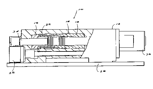
Figure 1 is a side view partly sectioned of a percussion mechanism for a rock
drill
according to the invention,
Figure 2 is a side view partly sectioned of portion of the mechanism shown in
Figure 1, on an enlarged scale, and
Figure 3 is a view similar to Figure 2 illustrating the way in which a control
valve
is secured in position according to the invention.
DESCRIPTION OF PREFERRED EMBODIMENT
Figures 1 and 2 illustrates a percussion mechanism 10 for a rock drill
according
P.17540

CA 02161129 1999-11-OS
Page 4
to the invention. The mechanism includes a main body 12 in which is formed a
chamber 14. Located inside the chamber are a rear cylinder 16 with a
cylindrical
section 16A and a front cylinder 18 with a reduced diameter section 18A.
The cylinders are inter-engageable with one another, as is seen more clearly
in
Figure 2. The sections 16A and 18A define between them a volume 20. A
reciprocating cylindrical distribution valve 22 is positioned inside the
volume 20.
The two cylinders include ports 26 and 28 and 26A and 28A respectively.
An inner surface of the front cylinder 18 forms part of a sleeve 30 for a
piston 32.
As shown in Figure 2 opposing ends 34 and 35 of the piston extend from
opposing ends of the chamber 14 in the main body 12. A drill shank engaging
part 36, see Figure 1, is located on the right hand side of the body, to be
contacted by the end 35 of the piston 32.
The piston 32 has two spaced lands 48 and 50. A port 54 is provided through
the
front cylinder and feeds hydraulic oil to a front side of the land 50.
Figure 1 illustrates the body 12 mounted to a cradle 56. Apparatus 58 for
imparting rotary movement to the drill shank engaging part 36 is mounted to
the
body 12. The apparatus 58 functions in a known manner which is not relevant to
an understanding of the present invention.
The valve 22 is used as a distributor valve to control the flow of hydraulic
fluid
from a suitable hydraulic source through the ports 26 and 26A, into the
annular
P.17540

CA 02161129 1999-11-OS
Page 5
space inside the sleeve 30 to the left of the land 48, see Figure 2, and to
return
flow from the annular space via the ports 28 and 28A. The annular area on the
left
hand side of the land 48, extending around the shank of the piston 32, is
relatively
large. The annular area in front of the land 50 is relatively smaller. By
having both
annular areas pressurized simultaneously the piston works like a hydraulic
differential cylinder forcing the piston forwards delivering a blow to the
part 36
and hence to a drill shank which is engaged with the part 36. During the blow
the
valve 22 reacts and changes its location. The pressure is released behind the
land 48. Fluid entering the port 54 then drives the piston to the left, on its
return
stroke, for the forces on the opposing annular areas of the lands 48 and 50
are
counter balanced and there is a net force due to the pressure acting on the
annular area on the right hand side of the land 50.
While the piston moves on its return stroke fluid held within the sleeve 30,
to the
left of the land 48, is expelled through the ports 28A and 28. The valve is
then
again switched and pressure fluid is admitted through the ports 26 and 26A to
drive the piston on a percussion stroke.
It is to be noted that the valve 22 is located in the volume 20 which is
formed
between opposing surfaces of the rear and front cylinders 16 and 18
respectively.
The valve is therefore not in contact with the piston which is rotating, and
reciprocating at a high frequency of from 40Hz to 60Hz. Wear on the valve is
therefore reduced. Tolerances between the valve 22 and cylinders 18 and 16 can
be minimized reducing oil leakages and heat build up.
The opening speeds for the oil channels between the ports 26 and 26A and 28
and
P.17640

CA 02161129 1999-11-OS
Page 6
28A are high due to the large circular surface of the valve 22. The fast
opening
speed rapidly accelerates the piston and increases percussion power and
efficiency.
If the piston should fail then damage may be caused to the cylinder 18 but it
is
unlikely that the cylinder 16 or valve 22 will be damaged.
A possible modification to the mechanism is to replace the cylinders 16 and 18
by three or more components. For example the cylinder 16 can be separated into
two components along a plane X, while the cylinder 18 can also be separated
into
two components along a plane Y. Modifications of this type, which ease the
manufacture of the construction, are intended to fall inside the scope of the
invention.
Figure 3 is similar in many respects to Figure 2 and like reference numerals
are
therefore used to indicate like components. Differences in construction are
described hereinafter.
A stop piece 142 is positioned on the section 18A, at one end of the section,
and
is precisely secured thereto by means of any suitable process for example by
one
or more of the following: welding, fusion, an adhesive, a friction or
interference
fit, or by mechanical deformation of one or both respective components. In
this
example the components may be welded or fused together along a line
designated by the numeral 144. The stop piece 142 is placed in position on the
section 18A, and secured thereto, only after the valve 22 has been placed on
the
section 18A. The stop piece is precisely positioned relatively to the section
18A
P.17640

CA 02161129 1999-11-OS
Page 7
to ensure that the stroke of the valve 22 is accurately determined. It is to
be noted
that, on the left hand side of the section 18A, the stop piece 142 forms a
shoulder
which prevents further movement of the valve 22 to the left in the drawing
while,
on the right hand side of the section 18A, the cylinder 18 is formed
integrally, in
one piece, with a shoulder 146 which prevents movement of the valve, to the
right
in the drawing, beyond the shoulder.
It is essential for effective operation of the control valve mechanism to
control the
stroke of the valve 22 accurately to a predetermined stroke length. By
securing
the stop piece 142 to the section 18A in the manner described this objective
can
be achieved in a reliable manner. Further as the stop piece is integral, as
defined,
with the section 18A the stroke length of the valve is not affected by
component
tolerances, and forces which arise from vibrations or shock loadings imparted
to
the rock drill during use. This position is to be contrasted with what is the
case
with similar valves known to the applicants in which the valve stroke is
determined by means of two or more components which are releasably secured
to one another for example by means of bolts.
P.17640

Representative Drawing
A single figure which represents the drawing illustrating the invention.
Administrative Status

2024-08-01:As part of the Next Generation Patents (NGP) transition, the Canadian Patents Database (CPD) now contains a more detailed Event History, which replicates the Event Log of our new back-office solution.

Please note that "Inactive:" events refers to events no longer in use in our new back-office solution.

For a clearer understanding of the status of the application/patent presented on this page, the site Disclaimer , as well as the definitions for Patent , Event History , Maintenance Fee  and Payment History  should be consulted.

Event History

Description Date
Inactive: IPC from MCD 2006-03-12
Time Limit for Reversal Expired 2003-04-22
Letter Sent 2002-04-22
Grant by Issuance 2000-02-01
Inactive: Cover page published 2000-01-31
Inactive: Received pages at allowance 1999-11-05
Pre-grant 1999-11-05
Inactive: Final fee received 1999-11-05
Notice of Allowance is Issued 1999-07-08
Letter Sent 1999-07-08
Inactive: Approved for allowance (AFA) 1999-06-04
Letter Sent 1999-05-27
Reinstatement Requirements Deemed Compliant for All Abandonment Reasons 1999-05-10
Deemed Abandoned - Failure to Respond to Maintenance Fee Notice 1999-04-20
Amendment Received - Voluntary Amendment 1999-03-05
Inactive: S.30(2) Rules - Examiner requisition 1998-12-16
Inactive: Status info is complete as of Log entry date 1997-07-29
Inactive: Application prosecuted on TS as of Log entry date 1997-07-29
Request for Examination Requirements Determined Compliant 1997-04-14
All Requirements for Examination Determined Compliant 1997-04-14
Application Published (Open to Public Inspection) 1994-10-27

Abandonment History

Abandonment Date Reason Reinstatement Date
1999-04-20

Maintenance Fee

The last payment was received on 1999-05-10

Note : If the full payment has not been received on or before the date indicated, a further fee may be required which may be one of the following

  • the reinstatement fee;
  • the late payment fee; or
  • additional fee to reverse deemed expiry.

Please refer to the CIPO Patent Fees web page to see all current fee amounts.

Fee History

Fee Type Anniversary Year Due Date Paid Date
Request for examination - standard 1997-04-14
MF (application, 4th anniv.) - standard 04 1998-04-20 1998-04-14
Reinstatement 1999-05-10
MF (application, 5th anniv.) - standard 05 1999-04-20 1999-05-10
Final fee - standard 1999-11-05
MF (patent, 6th anniv.) - standard 2000-04-20 2000-04-19
MF (patent, 7th anniv.) - standard 2001-04-20 2001-04-06
Owners on Record

Note: Records showing the ownership history in alphabetical order.

Current Owners on Record
JARMO UOLEVI LEPPANEN
ROGER ROBARTS BRIGGS
Past Owners on Record
None
Past Owners that do not appear in the "Owners on Record" listing will appear in other documentation within the application.
Documents

To view selected files, please enter reCAPTCHA code :


To view images, click a link in the Document Description column. To download the documents, select one or more checkboxes in the first column and then click the "Download Selected in PDF format (Zip Archive)" or the "Download Selected as Single PDF" button.

List of published and non-published patent-specific documents on the CPD .

If you have any difficulty accessing content, you can call the Client Service Centre at 1-866-997-1936 or send them an e-mail at CIPO Client Service Centre.


Document
Description 
Date
(yyyy-mm-dd) 
Number of pages   Size of Image (KB) 
Claims 1999-03-05 2 80
Abstract 1999-11-05 1 13
Description 1999-11-05 7 258
Cover Page 1996-03-14 1 16
Description 1994-10-27 7 259
Abstract 1994-10-27 1 45
Claims 1994-10-27 2 69
Drawings 1994-10-27 2 33
Representative drawing 1998-07-14 1 8
Cover Page 2000-01-21 1 40
Representative drawing 2000-01-21 1 8
Commissioner's Notice - Application Found Allowable 1999-07-08 1 165
Courtesy - Abandonment Letter (Maintenance Fee) 1999-05-18 1 186
Notice of Reinstatement 1999-05-27 1 172
Maintenance Fee Notice 2002-05-21 1 179
PCT 1995-10-21 13 391
Correspondence 1999-07-08 1 99
Correspondence 1999-11-05 9 312
Fees 1997-03-14 1 61
Fees 1996-04-15 1 50