Note: Descriptions are shown in the official language in which they were submitted.
2161288
POROUS METAL BODY, PROCESS FOR PRODUCING THE SAME
AND BATTERY PLATE FORMED THEREFROM
BACKGROUND OF THE INVENTION
1. Field of the Invention
The present invention relates to a porous metal
body for use as a battery plate (i.e., a plate used in
a battery) or a carrier of any of various substances.
2. Description of the Prior Art
Porous metal bodies each provided with
interconnected pores at a porosity of 90% or higher
are commercially available which include, for example,
cELMElr (trade name) produced by Sumitomo Electric
Industries, Ltd. This is a porous metal body composed
of metallic Ni, being used in various types of filters
and plates for secondary alkaline batteries.
The above porous metal bodies have been produced
by either the plating process as described in, for
example, Japanese Patent Laid-Open No. 174484/1982 or
the sintering process as described in, for example,
Japanese Patent Publication No. 17554/1963. The
plating process comprises coating the skeletal surface
of a foamed resin such as urethane foam with carbon
powder or the like to thereby render the foamed resin
conductive, electrodepositing a metal thereon by the
electroplating process and thereafter burning the
foamed resin and carbon or the like to thereby obtain
a porous metal body. On the other hand, in the
sintering process as described in Japanese Patent
Publication No. 17554/1963, a porous metal body is
2161288
produced by impregnating the skeletal surface of a
foamed resin such as urethane foam with a slurried
metal powder to thereby obtain a slurry-coated
composite, drying the composite and heating the dried
composite to thereby sinter the metal powder.
Also, a process for producing a porous Al body
by casting has been reported (Nikkei Mechanical,
1981/1/5 issue, pages 22 and 23). In this casting-
based process, first, a slurry gypsum is cast into a
foamed resin such as urethane foam and set to thereby
prepare a gypsum mold having a two-dimensional network
structure. An Al melt is then cast into the mold, and
the gypsum mold is finally removed to thereby obtain a
porous Al body.
With respect to major uses of the above porous
metal body, recent attention is being drawn to the use
as a plate for secondary battery. Actually, the above
porous Ni body is being employed in Ni-Cd and Ni-
hydrogen secondary batteries. In recent years, a
secondary lithium battery is being high-lighted as
being suitable for meeting the demand for battery
capacity increase. In this secondary lithium battery,
the màterial composing the positive-electrode plate is
required to have oxidation and electrolyte resistances
because the cell voltage exceeds 3 V. From the
viewpoint of the material quality, the porous Ni body
cannot be used. Currently, an aluminum foil is being
employed as the material for composing the positive-
electrode plate, and the use of a porous Al body
therefor has been proposed (Japanese Patent Laid-Open
No. 28163/1992). In this laid-open specification,
lithium or a lithium alloy is used as an active
substance of a negative electrode, and it is described
that causing the positive-electrode collector to have
21612~8
--3--
a porous structure retards the deterioration of
discharge capacity by repeating charging and
discharging cycles.
Although the materials of most of the
conventional porous metal bodies are composed of Ni,
the porous body of Ni cannot occasionally be employed
in uses requiring lightweight and corrosion and
oxidation resistances. Further, in uses as filters,
and carriers for battery plates, etc., in which large
effective surface areas are required, the porous body
of Ni formed according to the plating process cannot
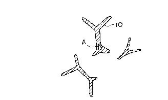
- be effectively utilized because its typical skeletal
sectional form is hollow as shown in Fig. 2 (a), so
that there is a substantially dead space such as part
A being a useless space. In this figure, numeral 10
represents a metal part. With respect to the porous
body of Ni prepared according to the sintering process
on the other hand, although its sectional form is as
shown in Fig. 2(b) and a hollow dead space as shown in
Fig. 2(a) is scarce therein, its configuration has a
thin skeleton and its surface area (skeletal periphery
in Fig. 2(b)) is small, so that from the viewpoint of
effectivity its structure also cannot be highly
appreciated.
With respect to the production of the porous
body of Al, for example, the plating process cannot be
applied thereto because Al plating is practically
almost unfeasible. Further, it is very difficult in
the sintering process to sinter powdery Al having a
strong oxide film formed at its surface under
atmospheric pressure, so that the process as described
in Japanese Patent Publication No. 17554/1963 cannot
directly be applied to the production of the porous
body of Al. Still further, in the casting process, it
2~61288
is difficult to obtain a porous body having a large
number of pores per unit length, i.e., minute pore
diameters in view of the productive characteristics of
the process.
Although the primary object is attained by the
formation of an electrode layer based on a positive-
electrode plate of aluminum foil or the like as
currently employed in the secondary lithium battery, a
plate material is desired which ensures higher
reliability, being free from deterioration of output
characteristics and capacity irrespective of the
repetition of charge and discharge, and which has
excellent adherence to electrode substances. That is,
generally, the repetition of charge and discharge a
number of times causes the positive electrode as a
whole to gradually swell to thereby deteriorate the
interfacial contact between the core material and the
electrode layer with the result that the conductivity
of the electrode per se is deteriorated so as to
render the attainment of high current density
unfeasible and to shorten tlle duration of charge and
discharge cycle. Further, powder comes off from the
plate~and causes short-circuit, so that there has been
a problem in, for example, reliability. These
problems have partly been attributed to the occurrence
of a reaction causing lithium ions to enter the
crystal lattice at the time of charge and discharge
reaction with the result that the crystal lattice of
the active substance is swollen or shrunk by doping or
dedoping with lithium ions so as to bring about the
occurrence of defects in the interfaces between the
electrode layer and the collector, between the active
substance and the plate and between the active
substance and the binder resin. Furthermore, a
2161288
problem of battery reliability is contemplated which
- is attributed to the deterioration of the active
substance layer resulting from the occurrence of local
heat caused by the low heat conductivity of each of
the electrode materials such as the active substance.
In the proposal (Japanese Patent Laid-Open No .
28163/1992) in which a porous body of Al is used as a
plate for suppressing the falling and peeling of the
active substance from the positive electrode and thus
for improving the charge and discharge cycle
characteristics of the nonaqueous-electrolyte-based
secondary battery, it is described that the
deterioration of discharge capacity by repeating
charge and discharge cycle is retarded by the
employrnent of lithium or a lithium alloy as an active
substance of a negative electrode and by the
employment of a positive-electrode plate having a
porous structure. However, the description is limited
to average pore diameters, any effective configuration
as a porous body is not specified, and there is no
clear process for production illustrated.
Any of the prior art processes do not provide a
complète resolution, and the current situation is that
any of them can hardly be stated as leading to
retention of the cycle life satisfactory for enabling
practical use.
SUMMARY OF THE INVENTION
The object of the present invention is to
provide a porous metal body having a large effective
surface area and a high space utilization factor and
to provide an excellent filter or battery plate by the
use thereof.
The contents of the present invention made for attaining the
above object will be described below.
The porous metal of the present invention contains Al as the
principal component, has a porous structure of three-dimensional
network provided with interconnected pores at a porosity of 90~ or
higher and has at least 10 pores per cm, which comprises metallic
skeleton parts whose average sectional form satisfies the
relationships represented by the following formulae:
S1/S2 < 2 and L1/L2 < 0.1
wherein
15 S1 = area of a closed region in one metallic skeletal
section,
S2 = area of a region filled with at least one metal in
a closed region in one metallic skeletal section,
L1 = maximum thickness of one metallic skeletal section,
and
L2 = outer peripheral length of one metallic skeletal
section.
The S1/S2 and L1 and L2 of the average sectional form means
the average value of S1/S2 or L1/L2 obtained by adding the
individual values of S1/S2 or L1/L2 of the respective metallic
skeletal sections and dividing the sum by the number of the
sections.
The configuration of a representative porous metal body of the
present invention as defined by the above formulae is as shown in
Fig. 1 and is large in the effective surface area than those of the
conventional porous structures as shown in Fig. 2(a)and (b). This
together with the possession of interconnected pores at a high
porosity provides a structure highly effective in use in filters and
i~ ~
2161288
carriers for battery plates, etc. Moreover, the
porous metal body of the present invention has
excellent oxidation and corrosion resistances because
its principal component is Al, so that it can be
employed in uses where the conventional porous bodies
of Ni have not been of avail.
With respect to the porous structure of the
present invention, its mechanical strength can be
ensured and its structural stability brought about by
containing one or more metal elements other than Al.
It is preferred that at least one element selected
from the group consisting of Bi, Ca, Co, Cu, Fe, Ge,
In, La, Li, Mg, Mn, Ni, Si, Sn and Zn be employed as
the above metal element. The presence of such elements
other than Al would occasionally be detrimental to the
corrosion resistance, etc., depending on the
environment. Thus, as another feature of the present
invention, a structure of porous metal body is
proposed in which a second element has its
concentration distribution high in the center of the
metal skeleton and has its concentration lowered at
the surface of the skeleton, i.e., the part brought
into direct contact with the outside environment. A
porous metal body having its structural stability
ensured and freed of the corrosion and other problems
can be obtained by virtue of the above structure.
Now, the process for producing the above porous
metal body will be described.
In the process for producing the above-mentioned
porous metal body according to the present invention,
first, a coating film of at least one metal capable of
forming a eutectic alloy at temperatures not higher
than the melting point of Al iS formed on the skeleton
of a foamed resin having a three-dimensional network
2161288
structure such as polyurethane foam according to the
plating, vapor deposition, sputtering, CVD or other
vapor phase process. The thickness of the above
coating film is preferred to be not greater than 5 ~m
from the viewpoint of its effect and practicability.
It ls preferred that at least one element selected
from the group consisting of Bi, Ca, Co, Cu, Fe, Ge,
In, La, Li, Mg, Mn, Ni, Si, Sn and Zn be employed as
the above metal.
Subsequently, the above foamed resin having the
coating film formed thereon is immersed in a paste
comprising powdery Al, a resin as a binder and an
organic solvent and passed through an interstice
between rolls to thereby form a coatirig film
comprising powdery Al containing organic components
such as the binder. The thickness of the coating film
can be easily regulated by controlling the roll gap.
Thereafter, the composite is heated in a nonoxidizing
atmosphere, thereby burning the organic components and
sintering the powdery A1. Thus, a porous metal body
is obtained. The heating is conducted at a
temperature ranging from 550~C to 750~C. The
temperature is preferred to range from 620 to 700~C.
Although the heating may be conducted in a vacuum
atmosphere, N2, Ar and H2 atmospheres are preferred
from the economic point of view.
In substitution for the above powdery Al, a
powdery mixture of the powdery Al and powder of at
least one metal selected from the group consisting of
Bi, Ca, Co, Cu, Fe, Ge, In, La, Li, Mg, Mn, Ni, Si, Sn
and Zn, powder of an alloy of Al and at least one
metal selected from the group consisting of Bi, Ca,
Co, Cu, Fe, Ge, In, La, Li, Mg, Mn, Ni, Si, Sn and Zn
or a mixture of the powdery Al and this alloy powder
2161288
can be used as the metal component of the paste. It
is preferred that the ratio of the metal component
other than Al of the finally obtained porous metal
body be 20% by weight or below for ensuring the
excellent properties of Al such as lightweight and
oxidation and corrosion resistances.
The thus obtained porous metal body of the
present invention is used as a positive-electrode core
plate in a battery provided with a chargeable positive
electrode, a chargeable negative electrode and a
lithium-ion-containing nonaqueous electrolyte.
BRIEF DESCRIPTION OF THE DRAWINGS
Fig. 1 is a schematic view of a skeletal section
of the porous metal body of the present invention.
Fig. 2 is typical skeletal sections of the
conventional porous body of Ni prepared according to
the plating process, in which part (a) shows a hollow
section and part (b) a solid section.
Fig. 3 is a schematic view of skeletal sectional
forms observed before and after a sintering step in
the process of the present invention.
Fig. 4 is a view showing the Cu profiles of
skeletal section parts of Example 1 and Comparative
Example 1.
Fig. 5 is an explanatory .sectional view showing
one form of the structure of a battery having the
plate of the present invention employed therein; and
Fig. 6 is a graph showing the cycle
characteristics evaluated for the batteries according
to the present invention and comparative examples.
DETAILED DESCRIPTION OF THE PREFERRED EMBODIMENTS
8 ~
- 10 -
With respect to the structure of the porous metal body of the
present invention, as shown in Fig. 1 the principal component of
the porous metal body is Al having excellent oxidation and corrosion
resistances, so that the porous metal body can be used in
application fields where the conventional porous bodies of Ni have
been of no avail. Further, having a high space utilization factor
and a large surface area ensures effective action in uses in filters
and carriers for battery plates, etc. The function of the porous
metal body of the present invention in the secondary Li battery will
be described below.
The employment of the Ni-made continuous porous metal body having
interconnected pores and a three-dimensional network in the
positive-electrode plate of the secondary Li battery has advantages
in that three-dimensional continuous pores are provided at a
porosity of 90~ or higher, so that not only can the active substance
be filled in the pore space but also the retention of the active
substance in the network space is excellent. However, actually, the
Ni-made porous metal body cannot be of avail because it is dissolved
when the charging voltage of the chargeable oxide for use as an
active substance of the positive electrode is as high as over 3 V.
On the other hand, the porous metal body of the present invention
comprises Al as the principal component, so that it is not dissolved
even when the charging voltage exceeds 3 V with the result that
the duration of charge and discharge cycle can be prolonged. Another
marked effect of the present invention resides in that the porous
metal body of the present invention is free of a dead space A such
as corresponding part A of Fig.2 (a) to thereby have high space
utilization factor and its effective surface area is large
A
- 11 - 7c ~
compared with that of the conventional porous body, so that not
only can the active substance material be filled therein in an
increased ratio but also the area of contact between the active
substance material and the metallic skeletal pat 10 is increased
with the adherence therebetween improved. Thus, a large effective
space results to thereby increase the filling ratio of the active
substance material. Further, a large contact area results to
thereby impart capability of conducting electrons with the result
that the amount of conductive material to be added can be reduced.
These two advantages contribute to an increase of the real fill
of the active substance material. Still further, the falling of
the active substance and conductive material from the plate at the
repetition of charge and discharge cycle can be avoided, so that
the deterioration of output characteristics and capacity can be
suppressed, thereby enabling striking prolongation of the
duration of charge and discharge cycle. Furthermore, the
structure is realized in which the positive-electrode materials
are filled in the three-dimensional network structure composed
of Al having high heat conductivity, so that the heat conductivity
of the positive-electrode plate as a whole is improved to thereby
achieve improvement in respect of the reliability lowering and
life shortening attributed to local heat build-up.
Below, the function and effect of the process of the present
invention will be described.
The process for producing a porous metal body according to the
present invention is one in which powdery Al whose sintering is
difficult because of the~
A---
2161288
-12-
presence of a strong oxlde film at the surfaee thereof
is sintered to thereby obtain a porous metal body.
The eharaeteristic feature of this process resides in
forming a eoating film of a second metal element
(i.e., at least one selected from the group eonsisting
of Bi, Ca, Co, Cu, Fe, Ge, In, La, Li, Mg, Mn, Ni, Si,
Sn and Zn) eapable of forming a euteetie alloy with Al
at temperatures not higher than the melting point of
Al on a foamed resin having a three-dimensional
network strueture.
The powdery Al applied onto the metal coating
film induces a eutectic reaction at the interface
between the powdery Al and the sublayer metal coating
film during the heating treatment to thereby produce a
liquid phase surface at temperatures not higher than
the melting point of Al. This partially produeed
liquid phase surface breaks the Al oxide film to
thereby progress the sintering of the powdery Al while
maintaining the skeletal structure of three-
dimensional network.
- The metal coating film is present nearly
throughout the entire surface of the sublayer eoated
with the powdery Al, so that the euteetie reaetion
oeeurs uniformly throughout the entire surfaee of the
sublayer and the metal eoating film partly remains.
Consequently, sintering shrinkage seareely oeeurs
along the intra-skeletal-surface direetion with
shrinkage oecurring only along the thickness direetion
(direction from applied powdery Al toward the sublayer
film). Fig. 3 is a schematie view of the eonfigura-
tions of skeletal sections which would appear before
and after the sintering in accordance with the above
contemplated mechanism.
Therefore, size shrinkage scarcely occurs after
the sintering, so that the configuration results in which the resin
core skeleton part occupied by the foamed resin 11 before the
sintering is filled (not shown) with the metal part 10. In Fig. 3,
numerals 12 and 13 represent the metal coating film and the powdery
Al, respectively. Thus, the structure of the porous metal body of
the present invention can be obtained.
The above phenomenon occurs according to the above mechanism, so
that it is observed only when the metal coating film 12 is formed
on the foamed resin. For example, when a powdery mixture composed
of the above metal element capable of forming a eutectic alloy and
dispersed in powdery form in the powdery Al is applied in
substitution for the coating film, isotropic sintering shrinkage
occurs with the result that only the skeletal sectional form as
shown in Fig. 2 (b) is obtained.
The above process of the present invention leads to the presence
of the second metal element (s) constituting the coating metal film
at high concentrations in the center of the skeleton, so that, as
another feature of the porous metal structure of the present
invention, the structure of porous metal body can be obtained in
which the second element has its concentration distribution high in
the center of the metal skeleton and has its concentration lowered
at the surface of the skeleton, i.e., the part brought into direct
contact with the outside environment.
Not only can the same effect as above be obtained but also a
sinterability improving effect is exerted by the use of, in
substitution for the above powdery Al, a powdery mixture of the
powdery Al and powder of the second metal element, powder of an
alloy of Al and the second metal element or a powdery
2161288
-14-
mixture of the powdery Al and this alloy powder in
accordance with the other feature of the present
invention.
The present invention will be illustrated below
with reference to the following Examples.
Example 1
A metal coating film of Cu was formed at an
amount of 5 g/m2 on polyurethane foam having a
thickness of 1.5 mm and provided with about 20 pores
per cm according to the electroless plating process.
Powdery Al of 16 ~m in average particle size
were blended with the compounding agents specified in
Table 1 in the proportions also specified therein and
mixed by means of a ball mill for 12 hr, thereby
obtaining a paste.
Table 1
Compoundinq aqent Proportion
powdery Al 50 wt%
(average particle size: 16 ~m)
20 acrylic resin 8 wt%
2-(2-n-butoxyethoxy)ethanol 42 wt%
The polyurethane foam having the coating film of
Cu formed thereon was impregnated with the paste
specified in Table 1, freed of excess impregnation
coating by means of a squeezing extractor and dried in
the air at 150~C for 10 min. Thereafter, the coating
product was heated to 650~C at a temperature rise rate
of 10~C/min in a stream of N2, and heating treatment
was conducted at 650~C for 1 hr. Thus, a porous metal
body of the present invention was obtained.
As a comparative example, a porous metal body
2161288
I
was prepared in the same manner as in the above
Example, except that the polyurethane foam was not
provided with a coating film of Cu and that a paste
was prepared with the use of the compounding agents
specified in Table 2 in which powdery Cu having an
average particle size of about 10 ~m was used in
combination with powdery Al in the proportions also
specified in Table 2.
Table 2
ComPoundinq aqent Proportion
powdery Al
(average. particle size: 16 ~m) 48.2 wt%
powdery Cu
(average particle size: 10 ~m) 1.8 wt%
15 acrylic resin 8 wt%
2-(2-n-butoxyethoxy)ethanol 42 wt%
The properties of the above porous metal bodies
are given in Table 3. The Cu profile at a skeletal
section part was examined by an electron probe micro
analyzer and the result is ~wn in Fig. 4.
2161288
-16-
Table 3
Sam- Weight Porosity No. of Amount Sectional form *2
ple (g/m2) (%) pores *1 of Cu S1/S2 L1/L2
No. (wt.%)
1 143 95 20 3.5 1.1 0.04
2 145 93 25 3.5 1.3 0.21
(Comp. Ex.)
*1) Number of pores per cm, and
*2) Skeletal sections were cut out and the average
values of S1/S2 and L1/L2 were calculated with respect
to 10 skeletal sectional forms.
S1 = area of a closed region in one metallic
skeletal section,
S2 = area of a region filled with at least one
metal in a closed region in one metallic
skeletal section,
L1 = maximum thickness of one metallic
skeletal section, and
L2 = outer peripheral length of one metallic
skeletal section.
Example 2
The performance as a battery plate of each of
the porous metal bodies prepared in Example 1 was
evaluated.
Preparation of positive electrode:
LiCoO2 was employed as an active substance of
positive electrode. 95% by weight of LiCoO2 was mixed
with 2% by weight of acetylene black as a conductive
2161288
agent and then mixedltogether with 3% by weight of
polytetrafluoroethylene resin as a binder. The
polytetrafluoroethylene resin was added in the form of
an aqueous dispersion. The resultant pasty mixture
was filled in the three-dimensional pores of each of
the porous metal bodies prepared~in Example 1 (Nos. 1
and 2), and compression molding was carried out into a
thickness of 0.4 mm.
Preparation of neqative electrode:
Powdery graphite and polyethylene terephthalate
were milled together, applied to both sides of a
copper foil of 15 ~m in thickness as a negative-
electrode plate and dried, followed by compression
molding into a thickness of 0.4 mm. Thus, a negative
electrode was obtained.
Preparation of nonaqueous electrolYte:
LiPF6 (lithium hexafluorophosphate) as a solute
was dissolved in ethylene carbonate (EC) as a solvent
in a concentration of 1 mol/l , thereby obtaining a
nonaqueous electrolyte.
Preparation of secondarY nonaqueous electrolyte
battery:
A cylindrical battery (battery size: 14.2 mm in
diameter and 50.0 mm in length) was prepared from the
above positive and negative electrodes and nonaqueous
electrolyte.
A microporous film of polypropylene having a
three-dimensional pore structure (trade name "CELGARD
2161288
-18-
3401" produced by Polyplastics Co., Ltd.) was used as
a separator. This separator was impregnated with the
above nonaqueous electrolyte, and a battery
constructed as shown in Fig. 5 was produced. An
electrode body was formed by providing positive
electrodes 1 and negative electrodes 2, disposing a
strip separator 3 having a width greater than those of
the electrode plates between neighboring positive and
negative electrodes and spirally winding the whole.
The electrode body had its top and bottom parts
respectively provided with insulating polypropylene
plates 6, 7 and was inserted in a case 8. A step part
was formed at an upper part of the case 8, the
electrolyte was poured therein and a sealing plate 9
was applied for sealing. Thus, batteries were
prepared. In this figure, numerals 4 and 5 represent
a negative-electrode lead plate and a positive-
electrode lead platej respectively.
The battery in which use was made of porous
metal body No. 1 was designated battery B1 and the
battery in which use was made of porous metal body No.
2 (Comparative Example) designated battery B2.
~ s another comparative example, battery B3 was
prepared in which an aluminum foil of 20 ~m in
thickness was used as a positive-electrode plate
according to the prior art process. 85% by weight of
LiCoO2 as an active substance of positive electrode,
10% by weight of acetylene black as a conductive agent
and 5% by weight of polytetrafluoroethylene resin as a
binder were mixed together. The
polytetrafluoroethylene resin was added in the form of
an aqueous dispersion. The resultant pasty mixture
was uniformly applied onto both sides of the aluminum
foil and dried, followed by compression molding by
2161288
- 1 9 -
means of a roller press into a positive electrode with
a thickness of 0.4 mm. Except for the positive
electrode, the battery was constructed in the same
manner as in Example 1 according to the present
invention.
In battery evaluation tests, the energy density
was measured and further the change of battery
capacity was measured which occurred when the charge
and discharge cycle was repeated in the charge and
discharge cycle test in which one cycle consisted of
charging of 100 mA current to a charging ending
voltage of 4.2 V followed by discharging of 100 mA
current to a discharging ending voltage of 3.0 V.
Each test was conducted with respect to 10 cells, and
an average was calculated for comparison.
For each battery, the energy density result is
given in Table 4 and the cycle characteristic
evaluation result is shown in Fig. 6.
Table 4
Enerqy density (Wh/L)
, . .
B1 (Invention) 340
B2 (Comp. Ex.) 320
B3 (Comp. Ex.) 280
Fig. 6 is a graph in which the charge and
discharge cycle characteristic of each battery is
shown by the change of battery capacity caused by the
change in the number of cycles relative to the battery
capacity at first cycle employed as a reference on the
axis of ordinate.
As apparent from Table 4, batteries B1 and B2 in
each of which use was made of a plate with a porous
2161288
-20-
structure are endowed with relatively large energy
densities. Further, although identical in respect of
the use of a porous metal body, the battery B1 having
the porous metal body of the present invention
incorporated therein is endowed with higher energy
density. This is attributed to the porous body No. 1
having larger effective surface area.
The results of Fig. 6 show that, as compared
with the conventional battery B3 having an aluminum
foil employed therein (provided as a comparative
example) which retains at least 80% of the initial
capacity even after 1000 cycles, the battery B1 of the
present invention retains at least 90% of the initial
capacity even after 1000 cycles, thereby attesting to
the cycle life prolonged in the present invention.
The battery B2 has the greatest capacity lowering.
This would have been caused by leaching of Cu from the
porous metal body No. 2.
In the foregoing Examples, LiCoO2, graphite and
the ethylene carbonate solution having 1 mol/l
lithium hexafluorophosphate dissolved therein were
employed as a positive electrode, a negative electrode
and an electrolyte, respectively. The positive
electrode, negative electrode and electrolyte for use
in the secondary nonaqueous electrolyte battery of the
present invention are not limited to those employed in
the above Examples. The positive electrode can be one
containing LiMn2O4, LiNiO2 or the like in place of
LiCoO2, and the negative electrode can be one
containing any of carbon materials capable of being
doped or dedoped with metallic lithium, lithium alloys
and lithium ions.
In the foregoing Examples, embodiment of the
present invention has been described in connection
2161288
with the application to a cylindrical secondary
nonaqueous electrolyte battery. However, there is no
particular limit in the configuration of the battery.
The present invention can be applied to secondary
nonaqueous electrolyte batteries of various
configurations, for example, flat and angular
configurations.
Example 3
Various porous metal bodies were produced with
the use of the same polyurethane foam as in Example 1
but with the type of coating metal and the type of
metal powder in paste being varied. The details
thereof are specified in Table 5.
2161288
-22-
Table 5
Sample Coating Metal powder Heat treatment
No. metal *1 of paste *2 condition *3
3 Bi, 3 g/m2 Al (50 wt%) in Ar, 630~C, 30 min
4 In, 4 g/m2 Al (50 wt%) in Ar, 600~C, 1 hr
Si, 7 g/m2 Al (50 wt%) in N2, 670~C, 20 min
6 Mn, 2 g/m2 Al (50 wt%) in Ar, 580~C, 1 hr
7 Cu, 2 g/m2 Al (48 wt%~ ln H2, 630~C, 30 min
Mg (2 wt%)
8 Si, 4 y/m2 Al (49 wt%) in Ar, 590~C, 1 hr
Mn (1 wt~)
9 Sn, 5 g/m2 Al-Mg(2%) in Ar, 710~C, 10 min
alloy (50 wt%)
Fe, 3 g/m2 Al-Mn(1%) in N2, 730~C, 5 min
alloy (50 wt%)
11 Ni, 1 g/m2 Al-Si(20%) in Ar, 630~C, 30 min
alloy (10 wt%)
Al (40 wt%)
12 Mn, 2 g/m2 Al-Ca(10%) in Ar, 600~C, 1 hr
alloy (20 wt%)
Al (30 wt%)
*1) The coatings were all formed by the vapor
deposition process.
*2) The components other than metal powder or alloy
were the same as specified in Table 1.
*3) The temperature rise rate was the same as in
Example 1.
The sectional form of each of the obtained
porous metal bodies was examined in the same way as
described in Example 1 and the result is given in
Table 6.
2161288
-23-
Table 6
Sample No. Sectional form
S1/S2L1/L2
3 1.2 0.03
4 1.1 0.02
1.3 0.05
6 1.7 0.08
7 1.4 0.06
8 1.3 0.02
9 1.1 0.03
1.1 0.01
11 1.3 0.04
12 1.4 0.06
Table 6 demonstrates that a porous metal body
having a large effective surface area can be obtained
by the process of the present invention.
The porous metal body of the present invention
has a large effective surface area and a high space
utilization factor, so that it exhibits very excellent
performance in uses in filters and carriers for
battéry plates, etc.