Language selection

Search

Patent 2161296 Summary

Third-party information liability

Some of the information on this Web page has been provided by external sources. The Government of Canada is not responsible for the accuracy, reliability or currency of the information supplied by external sources. Users wishing to rely upon this information should consult directly with the source of the information. Content provided by external sources is not subject to official languages, privacy and accessibility requirements.

Claims and Abstract availability

Any discrepancies in the text and image of the Claims and Abstract are due to differing posting times. Text of the Claims and Abstract are posted:

  • At the time the application is open to public inspection;
  • At the time of issue of the patent (grant).
(12) Patent: (11) CA 2161296
(54) English Title: HEAT TRANSFER TUBE
(54) French Title: TUBE DE TRANSFERT THERMIQUE
Status: Deemed expired
Bibliographic Data
(51) International Patent Classification (IPC):
  • F28F 1/36 (2006.01)
  • F28F 1/42 (2006.01)
  • F28F 13/18 (2006.01)
  • F28F 17/00 (2006.01)
(72) Inventors :
  • GUPTE, NEELKANTH S. (United States of America)
  • LIU, XIN (United States of America)
  • SPENCER, STEVEN J. (United States of America)
  • CHIANG, ROBERT H.L. (United States of America)
  • GAFFANEY, DANIEL (United States of America)
(73) Owners :
  • CARRIER CORPORATION (United States of America)
(71) Applicants :
(74) Agent: GOWLING WLG (CANADA) LLP
(74) Associate agent:
(45) Issued: 1998-06-02
(22) Filed Date: 1995-10-24
(41) Open to Public Inspection: 1996-05-18
Examination requested: 1995-10-24
Availability of licence: N/A
(25) Language of filing: English

Patent Cooperation Treaty (PCT): No

(30) Application Priority Data:
Application No. Country/Territory Date
08/341,236 United States of America 1994-11-17

Abstracts

English Abstract


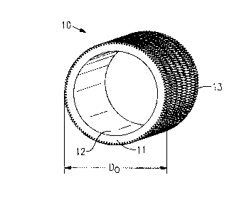
A heat transfer tube (10) for use in an application, such as a shell and tube type air
conditioning system condenser, in which a fluid flowing through the heat exchanger external to
the tubes condenses by transfer of heat to a cooling fluid flowing through the tubes. The tube
has at least one fin convolution (20) extending helically around its external surface (13). A
pattern of notches (30) extends at an oblique angle (a) across the fin convolutions at intervals
about the circumference of the tube. There is a spike (22) between each pair of adjacent
notches. The fin convolution, notches and spikes are formed in the tube by rolling the wall of
the tube between a mandrel and, first, a gang of finning disks (63) and, second, a notching
wheel (66). Because, during the manufacture ofthe tube, ofthe interaction ofthe rotating and
advancing tube and the notching wheel, the angle (,B) of inclination of the axis of the tip of the
spike is oblique with respect to the notch angle. The maximum width (W,) of the spike is
greater than the width (Wr) of the proximal portion of the fin convolution.


French Abstract

Tube de transfert thermique (10) pour utilisation dans une application, telle que dans un condenseur à calandre et à tube d'un circuit de climatisation, dans laquelle un fluide s'écoulant dans l'échangeur thermique à l'extérieur des tubes se condense par le transfert de chaleur à un fluide de refroidissement circulant dans les tubes. Le tube comprend au moins une circonvolution d'ailette (20) se prolongeant de façon hélicoïdale autour de sa surface externe (13). Un réseau d'entailles (30) se prolonge à un angle oblique (a) sur les circonvolutions d'ailette à intervalles égaux à la circonférence du tube. Une pointe (22) est placée entre chaque paire d'entailles avoisinantes. La circonvolution d'ailette, les entailles et les pointes sont formées dans le tube en roulant la paroi de ce dernier entre un mandrin et, premièrement, un ensemble de disques d'ailettage (63) puis, deuxièmement, une roue à entailler (66). En raison de l'interaction entre le tube qui pivote et avance et la roue à entailler pendant la fabrication du tube, l'angle (B) d'inclinaison de l'axe de l'extrémité de la pointe est oblique par rapport à l'angle de l'entaille. La largeur maximale (W) de la pointe est plus grande que la largeur (Wr) de la partie proximale de la circonvolution d'ailette.

Claims

Note: Claims are shown in the official language in which they were submitted.


We claim:
1. An improved heat transfer tube (10) in which the improvement comprises:
at least one external fin convolution (20) disposed helically about said tube;

notches (30) extending radially into said fin convolution at intervals about the cir-
cumference of said tube;
each of said notches having a base axis that is at an oblique angle (a) with re- spect to the longitudinal axis (AT) of said tube;
said notches dividing said fin convolution into a proximal portion (21) and a spike
portion (22) having a single distal tip (23),
said spike portion being between a pair of adjacent said notches and having a
maximum width (Wt) that is greater than the maximum width (Wr) of
said proximal portion and a distal tip axis (O that is oblique to said notch
base axis.
2. The tube of claim 1 in which:

there are 13 to 28 fins convolutions per centimeter (33 to 70 fin convolutions per
inch) of tube;
the ratio (Hf / Do) of the height of said fin convolution (Hf) to the outer diameter
of said tube (Do) is between 0.020 and 0.05;
the density of said notches in said fin convolution is 17 to 32 notches per centime-
ter (42 to 81 notches per inch);
the angle between said notch base axis and said tube longitudinal axis is between
40 and 70 degrees; and
the depth of said notches is between 0.2 and 0.8 of said fin convolution height.3. A heat transfer tube (10) comprising:
a tube wall (11) having an outer surface(13);


8


at least one fin convolution (20), formed by the interaction of a finning disk (63)
and a mandrel (64), extending from said tube outer surface;
notches (30), formed by a notching wheel (66), extending radially into said fin
convolution at intervals about the circumference of said tube and dividing said
fin convolution into a proximal portion and a spike portion (22),
each of said notches having a base axis that is at an oblique angle (.alpha.) with re-
spect to the longitudinal axis (AT) of said tube; and
said spike portion having a single distal tip (23),
said distal tip being between a pair of adjacent said notches and having a
maximum width (W1) that is greater than the maximum width (Wr) of
said proximal portion and a distal tip axis (.beta.) that is oblique to said notch
base axis.

Description

Note: Descriptions are shown in the official language in which they were submitted.


2l 6l296
` -
IIEAT TRANSFER TUBE
BACKGROUND OF THE INVENTION
This invention relates generally to heat ~ srer tubes of the type used in shell and tube
type heat ~ - c~ ,e. ~. More particularly, the invention relates to a tube for use in an applica-
tion such as a condenser for an air conditioning system.
A shell and tube type heat eych~nger has a plurality of tubes cont~ined within a shell
Thè tubes are usually arranged to provide a multiplicity of parallel flow paths for one of two
fluids bclwcen which it is desired to e-cl~ ,e heat. The tubes are h~ c~cd in a second fluid
that flows through the heat eYch~nger shell. Heat passes from the one fluid to the other fluid
by through the walls of the tube. In one typical application, an air conditioning system
condenser, a cooling fluid, usually water, flows through the tubes of the condenser. Refriger-
ant flows through the condenser shell, entering as a gas and leaving as a liquid. The heat
transfer characteristics of the individual tubes largely determine the overall heat l,~lsrer
capability of such a heat exchanger.
There are a number of generally known methods of improving the efficiency of heat
transfer in a heat transfer tube. One of these is to increase the heat l,~lsrer area of the tube.
In a condensing application, heat transfer pe~rc.~",allce is improved by ",~;".;,.;,-g the amount
of tube surface area that is in contact with the fluid.
One of the most common methods employed to increase the heat l,~nsrel area of a
heat exchanger tube is by placing fins on the outer surface of the tube. Fins can be made
separately and attached to the outer surface of the tube or the wall of the tube can be worked
by some process to form fins on the outer tube surface.
Beside the increased heat transfer area, a finned tube offers improved con-lçnsing heat
transfer performance over a tube having a smooth outer surface for another reason. The
condensing refrigerant forms a continuous film of liquid refrigerant on the outer surface of a
smooth tube. The presence of the film reduces the heat transfer rate across the tube wall.
Resistance to heat transfer across the film increases with film thickness. The film thickness on
the fins is generally lower than on the main portion of the tube surface due to surface tension
effects, thus lowering the heat transfer resistance through the fins.
It is possible, however, to attain even greater improvement in condçn~ing heat transfer
performance from a heat lla~rer tube as compared to a tube having a simple fin Pnh~ncem~nt

21 6129 ~


Such a tube is described and claimed in U.S. Patent 5,203,404, issued 20 April 1993 to
Chiang, et al. (the '404 tube), the ~ignee of which is the same entity as the ~sign~e of the
present invention.
SUMMARY OF THE INVENTION
The present invention is a heat ~ srer tube having one or more fin convo!utions
formed on its external surface. Notches extend at an oblique angle across the fin convolutions
at intervals about the ch~;ul,~rence ofthe tube.
The notches in the fin further h~,ease the outer surface area of the tube as colllp~d
to a conventional finned tube. In addition, the configuration of the finned surface belween the
notches promote drainage of refrigerant from the fin. In most applications, the tubes in a shell
and tube type air conditioning con-lçn~er run horizontally or nearly so. With holiGonLal tubes,
the notched fin configuration promotes drainage of con-lçn.~ing refrigerant from the fins into
the grooves between fins on the upper portion of the tube surface and also promotes drainage
of condensed refrigerant off the tube on the lower portion of the tube surface.
The density of notches in the fin convolutions on the tube of the present invention is
relatively high when compared to the same parameters in a prior art tube such as the '404
tube. The external surface area is therefore even larger. Furthermore, the increased number
of notches per convolution revolution results in a fin surface beh,veen the notches that is
spiked or "sharper" than prior art tubes such as the '404 tube, a configuration that even more
strongly promotes drainage of condensed refrigerant from the tube.
Manufacture of a notched fin tube can be easily and economically accomplished byadding an additional notching disk to the tool gang of a finning m~chine of the type that forms
fins on the outer surface of a tube by rolling the tube wall between an internal mandrel and
external finning disks.
BRIEF DESCRIPTION OF THE DRAWINGS
The accompal~ing drawings form a part of the specification. Throughout the draw-ings, like reference numbers identify like elements.

216129~


FIG. 1 is a pictorial view of the tube of the present invention.
FIG. 2 is a view illu~ ling how the tube of the present invention is m~nllf~ct~lred
FIG. 3 is a plan view of a portion of the external surface of the tube of the present in-
vention. ~
- FIG. 4 is a plan view of a portion a single fin convolution of the tube of the present in-
vention.
FIG. 5 is a generic sectioned elevation view of a single fin convolution of the tube of
the present invention.
FIGS. SA, 5B, 5C and 5D are sectioned elevation views, through, respectively, lines
5A-5A, 5B-5B, 5C-5C and 5D-5D in FIG. 4, of a single fin convolution of the tube of the
present invention.
DESCRIPTION OF THE PREFERRED EMBODIMENT
FIG. 1 is a pictorial view of heat transfer tube 10. Tube 10 comprises tube wall 11,
tube inner surface 12 and tube outer surface 13. E~t.on-ling from the outer surface of
tube wall 11 are external fins 22. Tube 10 has outer rli~metçr Do, incl-ltling the height of
fins 22.
The tube of the present invention may be readily m~nllf~ctllred by a rolling process.
FIG. 2 illustrates such a process. In FIG. 2, finning m~hinP 60 is opel~ g on tube 10, made
of a malleable metal such as copper, to produce both interior ribs and exterior fins on the tube.
Finning machine 60 has one or more tool arbors 61, each co~ inil~g tool gang 62, comprised
of a number of finning disks 63, and notching wheel 66. E?~tçn-ling into the tube is mandrel
shaft 65 to which is att~ched mandrel 64.
Wall 11 is pressed between mandrel 65 and finning disks 63 as tube 10 rotates. Under
pressure, metal flows into the grooves bet~,veen the finning disks and forms a ridge or fin on
the exterior surface of the tube. As it rotates, tube 10 advances between mandrel 64 and tool
gang 62 (from left to right in FIG. 2) resulting in a number of helical fin convolutions being
formed on the tube, the number being a function of the number of finning disks 63 in tool

. ~_ 2l6l296


gang 62 and the number of tool arbors 61 in use on finning m~l~.hine 60. In the same pass and
just after tool gang 62 forms fins on tube 10, notching wheel 66 i~ .lcsses oblique notches in
to the metal of the fins.
Mandrel 64 may be configured in such a way, as shown in FIG. 2, that it will impress
some type of pattern into the internal surface of the wall of the tube passing over it. A typical
pattern is of one or more helical rib convolutions. Such a pattern can inll)rove the efficiency of
the heat ~ srcl bclwcen the fluid flowing through the tube and the tube wall.
~ IG. 3 shows, in plan view, a portion of the external surface of the tube. Fxt~ntling
from outer surface 13 of tube 10 are a number of fin convolutions 20. Fxtending obliquely
across each fin convolution at intervals are a pattern of notches 30. Between each pair of
adjacent notches in a given fin convolution is a fin spike (22) having a distal tip 23. The fin
pitch, or ~ t~nce between adjacçnt fin convolutions, is Pr.
FIG. 4 is a plan view of a portion of a single fin convolution of the tube of the present
invention. The angle of in~.lin~tion of notch base 31 from longitll(lin~l axis of the tube AT is
angle a. The angle of inf.lin~tion of fin distal tip 22 from longitu-lin~l axis of the tube AT is
angle ,B. Because, during m~nllf~ctllre of the tube (see FIG. 2), of the interaction between
rotating and advancing tube 10 and notching wheel 66, the axis of spike 22 is turned slightly
from the angle between the teeth of the notching wheel and the fin convolution so that tip axis
angle ~ is oblique with respect to angle a, i.e., ,~ .~ a.
FIG. 5 is a pseudo sectioned elevation view of a single fin convolution of the tube of
the present invention. We use the term pseudo because it is unlikely that a section taken
through any part of the fin convolution would look exactly as the section depicted in FIG. 5.
The figure, however, serves to illustrate many of the features of the tube. Fin convolution 20
extends outward ~om tube wall 11. Fin convolution 20 has plo~lllal portion 21 and spike 22.
Exten-iing through the fin at the pseudo section illustrated in a notch having notch base 32.
The overall height of fin convolution 20 is Hr. The width of pro~il"al portion 21 is W, and the
width of spike 22 at its widest iimPn~ion is Wt. The outer t;Al,ellf,~y of spike 22 is distal
tip 23. The ~ t~nce that the notch penel~les into the fin convolution or notch depth is Dn.

`-- 21Gl29~


Notching wheel 66 (~IG. 2) does not cut notches out of the fin convolutions during the
m~mlfact~lring process but rather h"l,.esses notches into the fin convolutions. The excess
material from the notched portion of the fin convolution moves both into the region between
adjacP.nt notches and outwardly from the sides of the fin convolution as well as toward tube
wall 11 on the sides ofthe fin convolution . As a result, Wt is greater than Wr.
~ IGS. SA, 5B, 5C and 5D are sectioned elevation views of fin convolution 20 respec-
tively taken at lines 5A-SA, 5B-SB, 5C-5C and 5D-5D in ~IG. 4. The views show more
accurately the configuration of notched fin convolution 20 at various points as colllpared to
the pseudo view of ~IG. 5. The real~lres of the notched fin convolution ~i~c~1ssed above in
connection with ~IG. 5 apply equally to the illustrations in ~IGS. 5A, 5B, 5C and 5D.
We have tested a prototype tube made according to the teaçhin~ of the present inven-
tion. That tube has a nominal outer di~meter (DO) of 19 millimetçrs (3/4 inch), a fin height of
0.65 millimeter (0.0257 inches), a fin density of 22 fin convolutions per ce~ el~r (56 fin
convolutions per inch) of tube length, 122 notches per circulllrerellLial fin convolution, the axis
of the notches being at an angle of in~.lin~tion (a) from the tube longitu-lin~l axis (AT) Of 45
degrees and a notch depth of 0.20 millimet~r (0.008 inch). The tested tube has three fin
convolutions, or, as is the term in the art, three "starts." Test data indicates that the tube is 20
times as effective in refrigerant-to-tube wall heat transfer as a conventional tube having a
smooth outer surface.
Extrapolations from test data indicate that the external surface configuration of the
tube of the present invention is suitable for use in tubes having nomin~l outer diamet~rs of
from 12.5 millimeters (1/2 inch) to 25 millimeters (1 inch) where:
a) there are and 13 to 28 fin convolutions per cçntimet~r (33 to 70 fin convo-
lutions per inch) of tube length, i.e. the fin pitch is 0.36 to 0.84 millimeter (0.014 to
0.033 inch), or
0.036 mm < P, < 0.84 mm (0.014 inch < P, < 0.033 inch);
b) the ratio of fin height to tube outer di~meter is between 0.02 and 0.04, or
0.020<H~/Do<0.055;

21612


c) the density of notches in the fin convolution is 17 to 32 notches per centi-
meter (42 to 81 notches per inch);
d) the angle bc~ween the notch axis and the tube longit~l-lin~l axis is b~lwee
40 and 70 degrees, or
40 < a < 70 and
e) the notch depth is between 0.2 and 0.8 ofthe fin height or
0.2<Dn/Hf <0.8.

The op~ lulll number of fin convolutions or fin ''sta-rts~ depen~ls more on considera-
tions of ease of m~mlf~ctllre rather than the effect of the number on heat ll~lsrer p~l rOl ll.allce.
A higher number of starts increases the rate at which the fin convolutions can be formed on
the tube surface but increases the stress on the finning tools.

Representative Drawing
A single figure which represents the drawing illustrating the invention.
Administrative Status

For a clearer understanding of the status of the application/patent presented on this page, the site Disclaimer , as well as the definitions for Patent , Administrative Status , Maintenance Fee  and Payment History  should be consulted.

Administrative Status

Title Date
Forecasted Issue Date 1998-06-02
(22) Filed 1995-10-24
Examination Requested 1995-10-24
(41) Open to Public Inspection 1996-05-18
(45) Issued 1998-06-02
Deemed Expired 2009-10-26

Abandonment History

There is no abandonment history.

Payment History

Fee Type Anniversary Year Due Date Amount Paid Paid Date
Application Fee $0.00 1995-10-24
Registration of a document - section 124 $0.00 1996-01-11
Maintenance Fee - Application - New Act 2 1997-10-24 $100.00 1997-09-16
Final Fee $300.00 1998-02-13
Maintenance Fee - Patent - New Act 3 1998-10-26 $100.00 1998-09-18
Maintenance Fee - Patent - New Act 4 1999-10-25 $100.00 1999-09-16
Maintenance Fee - Patent - New Act 5 2000-10-24 $150.00 2000-09-19
Maintenance Fee - Patent - New Act 6 2001-10-24 $150.00 2001-09-19
Maintenance Fee - Patent - New Act 7 2002-10-24 $150.00 2002-10-23
Maintenance Fee - Patent - New Act 8 2003-10-24 $350.00 2004-05-13
Maintenance Fee - Patent - New Act 9 2004-10-25 $200.00 2004-09-24
Maintenance Fee - Patent - New Act 10 2005-10-24 $450.00 2006-01-24
Maintenance Fee - Patent - New Act 11 2006-10-24 $250.00 2006-09-20
Maintenance Fee - Patent - New Act 12 2007-10-24 $250.00 2007-09-21
Owners on Record

Note: Records showing the ownership history in alphabetical order.

Current Owners on Record
CARRIER CORPORATION
Past Owners on Record
CHIANG, ROBERT H.L.
GAFFANEY, DANIEL
GUPTE, NEELKANTH S.
LIU, XIN
SPENCER, STEVEN J.
Past Owners that do not appear in the "Owners on Record" listing will appear in other documentation within the application.
Documents

To view selected files, please enter reCAPTCHA code :


To view images, click a link in the Document Description column. To download the documents, select one or more checkboxes in the first column and then click the "Download Selected in PDF format (Zip Archive)" or the "Download Selected as Single PDF" button.

List of published and non-published patent-specific documents on the CPD .

If you have any difficulty accessing content, you can call the Client Service Centre at 1-866-997-1936 or send them an e-mail at CIPO Client Service Centre.


Document
Description 
Date
(yyyy-mm-dd) 
Number of pages   Size of Image (KB) 
Representative Drawing 1998-05-15 1 9
Cover Page 1996-03-18 1 17
Abstract 1996-03-18 1 27
Description 1996-03-18 6 265
Claims 1996-03-18 2 51
Drawings 1996-03-18 3 112
Cover Page 1998-05-25 2 74
Correspondence 1998-02-13 1 32
Correspondence 2004-03-10 1 2
Prosecution Correspondence 1995-10-24 3 132