Language selection

Search

Patent 2161521 Summary

Third-party information liability

Some of the information on this Web page has been provided by external sources. The Government of Canada is not responsible for the accuracy, reliability or currency of the information supplied by external sources. Users wishing to rely upon this information should consult directly with the source of the information. Content provided by external sources is not subject to official languages, privacy and accessibility requirements.

Claims and Abstract availability

Any discrepancies in the text and image of the Claims and Abstract are due to differing posting times. Text of the Claims and Abstract are posted:

  • At the time the application is open to public inspection;
  • At the time of issue of the patent (grant).
(12) Patent: (11) CA 2161521
(54) English Title: COMBINATION HOPPER
(54) French Title: TREMIE COMBINEE
Status: Expired and beyond the Period of Reversal
Bibliographic Data
(51) International Patent Classification (IPC):
  • B67C 11/00 (2006.01)
  • B67C 11/02 (2006.01)
(72) Inventors :
  • JOHANSON, JERRY RAY (United States of America)
(73) Owners :
  • JR JOHANSON, INC.
(71) Applicants :
  • JR JOHANSON, INC. (United States of America)
(74) Agent: BORDEN LADNER GERVAIS LLP
(74) Associate agent:
(45) Issued: 1999-03-30
(86) PCT Filing Date: 1994-04-26
(87) Open to Public Inspection: 1994-11-10
Examination requested: 1995-10-26
Availability of licence: N/A
Dedicated to the Public: N/A
(25) Language of filing: English

Patent Cooperation Treaty (PCT): Yes
(86) PCT Filing Number: PCT/US1994/004635
(87) International Publication Number: US1994004635
(85) National Entry: 1995-10-26

(30) Application Priority Data:
Application No. Country/Territory Date
08/055,672 (United States of America) 1993-04-29

Abstracts

English Abstract


A versatile one-dimensional hopper (12) is described as
well as structures that result when the one-dimensional hopper is
integrated with a conical bin (14) and when the one-dimensional
hopper is integrated with a V-blender (36, 38). In combining the
one-dimensional hopper with other structures, the diameter d of
the outlet is first specified, and then the slopes .theta.1 of the load-
bearing surfaces are chosen to achieve specified flow characteristics.
The load-bearing surfaces (22, 24) are then extended obliquely
upward until, at some height their maximum dimension measured
horizontally equals a value D determined by the structure to which
the one-dimensional hopper is to be attached. Where the surface
of the bin or other structure is higher than this height, vertical
surfaces (32, 34) that extend upwardly from the periphery of the
one-dimensional hopper are provided for the purpose of connecting
the one-dimensional hopper to the structure above it.


French Abstract

Trémie (12) à une dimension, polyvalente, et structures obtenues lorsque la trémie à une dimension est équipée d'une trémie conique (14) et lorsque la trémie à une dimension est équipée d'un mélangeur en V (36, 38). En associant la trémie à une dimension avec d'autres structures, on spécifie tout d'abord le diamètre d de la sortie puis on sélectionne les pentes 1 de surfaces supportant la charge pour obtenir les caractéristiques d'écoulement spécifiées. On étire ensuite les surfaces (22, 24) supportant la charge de manière oblique vers le haut jusqu'à une hauteur à laquelle leur dimension maximum mesurée horizontalemenet soit égale à une valeur D déterminée par la structure à laquelle doit être attachée la trémie à une dimension. Lorsque la surface de ls trémie ou d'une autre structure dépasse cette hauteur, les surfaces verticales (32, 34) qui sortent à l'extérieur de la périphérie de la trémie à une dimension sont prévues pour connecter la trémie à une dimension à la structure située au-dessus de cette dernière.

Claims

Note: Claims are shown in the official language in which they were submitted.


THE EMBODIMENTS OF THE INVENTION IN WHICH AN EXCLUSIVE
PROPERTY OR PRIVILEGE IS CLAIMED ARE DEFINED AS FOLLOWS:
1. A combination hopper for particulate material that prevents
ratholing and bin hangups while conserving headroom, characterized by the
combination of:
a one-dimensional hopper having a lower end and including
an outlet at the lower end, said outlet including four points A, B, C
and E successively spaced 90 degrees apart around said
outlet,
a pair of parallel planar vertical surfaces containing the points A
and C and spaced a distance d apart,
a pair of load-bearing surfaces confined between said pair of
parallel planar vertical surfaces, diverging upwardly from the
points B and E at angles .theta., with respect to the vertical, and
extending upward until, at a height h above said outlet, the
maximum dimension of said one-dimensional hopper in a
horizontal plane equals D;
a conical hopper including
a circular top of diameter D located at a height H greater than the
height h of said one-dimensional hopper, and concentric with
the outlet of said one-dimensional hopper,
a conical surface converging downwardly from said circular top at
a semi-apex angle .theta.2 with respect to the vertical said conical
surface containing an aperture formed by the upward
projection of said one-dimensional hopper;
said one-dimensional hopper joined to the conical surface of said conical
hopper with no part of said one-dimensional hopper extending above
the conical surface; and,
vertical surfaces extending up from said one-dimensional hopper and
connecting said one-dimensional hopper to the conical surface of
said conical hopper where the height of the conical surface above said
outlet exceeds h.

2. The combination hopper of Claim 1 wherein .theta. 1 is small enough to
provide downward flow of the particulate material along said pair of load-bearing
surfaces under the action of gravity when the combination hopper is full of
particulate material.
3. The combination hopper of Claim 1 wherein .theta. 2 is small enough to
render said conical hopper self-cleansing.
4. A combination hopper for particulate material that prevents
ratholing and bin hangups while conserving headroom, characterized by the
combination of:
a one-dimensional hopper having a lower end and including
an outlet at the lower end, said outlet including four points A, B, C
and E successively spaced 90 degrees apart around said
outlet,
a pair of parallel planar vertical surfaces containing the points A
and C and spaced a distance d apart,
a pair of load-bearing surfaces confined between said pair of
parallel planar vertical surfaces diverging upwardly from the
points B and E at angles .theta. 1 with respect to the vertical, and
extending upward until, at a height h above said outlet, the
maximum dimension of said one-dimensional hopper in a
horizontal plane equals D;
a conical hopper including
a circular top of diameter D located at a height H equal to the
height h of said one-dimensional hopper, and concentric with
the outlet of said one-dimensional hopper,

a conical surface converging downwardly from said circular top at
a semi-apex angle .theta. 2 with respect to the vertical, said conical
surface containing an aperture formed by the upward
projection of said one-dimensional hopper;
said one-dimensional hopper joined to the conical surface of said conical
hopper with no part of said one-dimensional hopper extending above
the conical surface.
5. The combination hopper of Claim 4 wherein .theta. 1 is small enough to
provide downward flow of the particulate material along said pair of load-bearing
surfaces under the action of gravity when the combination hopper is full of
particulate material.
6. The combination hopper of Claim 4 wherein .theta. 2 is small enough to
render said conical hopper self-cleansing.
7. The combination hopper of Claim 1 or 4 wherein said outlet is circular.
8. A V-blender for particulate material that prevents rat-holing and bin
hangups while conserving headroom, characterized by the combination of:
a one-dimensional hopper having a lower end and including
an outlet at the lower end, said outlet including four points A, B, C
and E successively spaced 90 degrees apart around said
outlet,
a pair of parallel planar vertical surfaces containing the points A
and C and spaced a distance d apart,

a pair of load-bearing surfaces confined between said pair of
parallel planar vertical surfaces, diverging upwardly from the
points B and E at angles .theta. 1 with respect to the vertical, and
extending upward until, at a height h above said outlet, the
maximum dimension of said one-dimensional hopper in a
horizontal plane equals D;
a bin including
a first hollow cylinder of diameter D having an axis inclined
at an angle .theta. 3 from a line through the points A
and C,
a second hollow cylinder of diameter D having an axis
inclined at an angle .theta. 3 from a line through the points
A and C and extending in a direction opposite said
first hollow cylinder,
said first hollow cylinder and said second hollow cylinder
intersecting each other and intersecting said
one-dimensional hopper,
the axes of said first hollow cylinder and said second hollow
cylinder intersecting at a height H above said outlet
greater than the height h of said one-dimensional
hopper;
said one-dimensional hopper joined to the downwardly-facing surfaces of
said first hollow cylinder and said second hollow cylinder with no
part of said one-dimensional hopper extending above the
downwardly-facing surfaces; and,
vertical surfaces extending up from said one-dimensional hopper and
connecting said one-dimensional hopper to the downwardly-facing
surfaces of said first hollow cylinder and said second hollow cylinder
where the height of the downwardly-facing surfaces above said
outlet exceeds h.

11
9. The V-blender of Claim 8 wherein .theta.1 is small enough to provide
downward flow of the particulate material along said pair of load-bearing surfaces
under the action of gravity when the V-blender is full of particulate material.
10. The V-blender of Claim 8 herein .theta.3 is large enough to render the
V-blender self-cleansing
11. The V-blender of Claim 8 wherein said outlet is circular.

Description

Note: Descriptions are shown in the official language in which they were submitted.


wo 94/25389 21~ 52 1 PCTIUS94/04635
~ 1
INTERNATIONAL APPLICATION
UNDER THE
PATENT COOPERATION TREATY
FOR
COMBINATION HOPPER
DESCRIPTION
Technical Field
The present invention is in the field of hoppers for use with solid
particulate materials, such as grain. More specifically, there is described a hopper
that is a combination of a conical bin and a one-dimensional hopper. The
5 combination hopper prevents rat-holing of the material and bin hangups, while
conserving on the vertical headroom required to accommodate the combination
hopper.
Background Art
In U.S. Patent No. 4,958,741 issued September 25, 1990 to the present
inventor, there is described a bin module that includes a first section that diverges
upwardly from a circular outlet to an oval-shaped upper edge. In the invention
of U.S. Patent No. 4,958,741, this first section is joined end-to-end to a second
section that provides a transition from an oval to a circular shape. This
arrangement differs from the arrangements described herein in two significant
ways.
First, in U.S. Patent No. 4,958,741 the sections are joined end-to-end. In
contrast, in the present invention, the sections are physically integrated, resulting
in reduced height.
Second, in U.S. Patent No. 4,958,741 the upper section has a specific
shape, which is dirrercllt from the shapes used in the present invention for the

WO 94125389 PCT/US94/0463~
~6~5~ ~
_ 2
upper section. In this way, the present invention is seen to extend the earlier
work to new ground; i.e., to shapes that were previously thought to be intractable.
Several considerations drive the design of hoppers. First, it is important
that the material not form a bridge or arch within the hopper, because such an
5 arch interferes with or tennin~tes the flow of material from the bottom of thehopper. If and when the arch collapses, the material may surge from the hopper.
It is well known that arching can be elimin~ted if the opening at the bottom of the
hopper is large enough.
A second consideration in the design of hoppers is that the wall of the
10 hopper must be steep enough so that the material will slide smoothly along the
wall during discharge. If the wall is not steep enough, a thick layer of material
will cling to the wall and discharge will take place from only a limited region near
the axis of the hopper, a condition referred to as "rat-holing." For a hopper
having the shape of a section of a right circular cone, the largest semi-apex angle
15 at which mass flow will occur, for a particular material is known as the mass flow
angle for that particular material.
The present invention is responsive to both of these considerations and
results in a combined hopper that eliminates both arching and rat-holing.
20 Disclosure of Invention
In accordance with the present invention, the limitations of the simple
conical hopper are overcome by integrating a one-dimensional hopper into a
conical hopper. The conical hopper and one-dimensional hopper are not merely
combined in succession, but instead are physically integrated into a single hopper
25 of complex shape.
Three embodiments of the combination hopper will be described below,
and the concept w~ll be applied to the design of a V-blender.
The novel features which are believed to be characteristic of the invention,
both as to olg~ tion and method of operation, together with further objects
30 and advantages thereof, will be better understood from the following description
considered in connection with the accompanying drawings in which several
preferred embodiments of the invention are illustrated by way of example. It is
A

WO 94125389 PCTfUS94104635
5 ~ ~
to be expressly understood, however, that the drawings are for the purpose of
illustration and description only and are not intended as a definition of the limits
of the invention.
Brief Description of the Drawings
Figure 1 is a front elevational view showing a first preferred embodiment
of the combination hopper;
Figure 2 is a side elevational view of the combination hopper of Figure 1;
Figure 3 is a top plan view of the combination hopper of Figure 1;
Figure 4 is a perspective view of the combined hopper of Figure 1;
Figure S is a front elevational view showing a second preferred
embodiment of the combination hopper;
Figure 6 is a side elevational view of the combination hopper of Figure S;
Figure 7 is a top plan view of the combination hopper of Figure S;
Figure 8 is a perspective view of the combination hopper of Figure ~;
Figure 9 is a front elevational view showing a third preferred embodiment
of the combination hopper of the present invention;
Figure 10 is a side elevational view of the combined hopper of Figure 9;
Figure 11 is a top plan view of the combination hopper of Figure 9;
Figure 12 is a perspective view of the combined hopper of Figure 9;
Figure 13 is a side elevational view of a V-blender employing the principles
of the present invention;
Figure 14 is a front elevational view of the V-blender of Figure 13;
Figure 15 is a top plan view of the V-blender of Figure 13; and,
Figure 16 is a perspective view of the V-blender of Figure 13.
Best Mode for Carry~ng Out the Invention
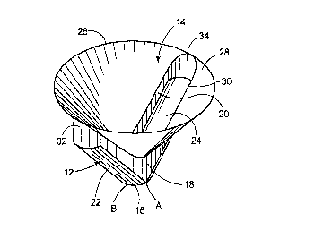
In the first preferred embodiment shown in Figures 1-4, the combination
hopper includes a one-dimensional hopper 12 that is surmounted by a conical
hopper 14. The one-dimensional hopper 12 includes an outlet 16 at its lower end for
discharging the particulate material. Although the outlet 16 would usually be
circular as shown in Figures 1-4, in alternative embodiments, the shape of the

w094/25389 ~ 5 ~ ~ i PCT/US94/04635
outlet may be rectangular or rhombic. As an aid to establishing directions, it is
helpful to consider that the points A, B, C and E are spaced 90 degrees apart
around the outlet, so that A is opposite C and B is opposite E, as best seen in
Figure 3. These points are also shown in Figures 1, 2 and 4.
The points A and C are spaced a distance d apart. Through the points A
and C pass planar vertical surfaces 18 and 20, respectively.
Load-bearing surfaces 22 and 24 are confined between the planes 18 and
20, and the load-bearing surfaces 22 and 24 diverge upwardly from the opposing
points B and E at angles ~ with respect to the vertical. As best seen in Figure
1, the load-bearing surfaces continue to diverge upwardly until, at a height h
above the outlet 16, they reach a m~ill~ulll dimension, measured in a horizontalplane, equal to D, the diameter of the conical hopper 14.
The load-bearing surfaces have a downwardly arched shape in the
preferred embodiment, but in other embodiments, the cross section of the load-
bearing surfaces may be flat or V-shaped.
In accordance with the present invention, the conical hopper 14 includes a
circular top 26 that is located at a height H not less than the height h of the one-
dimensional hopper 12. The circular top 26 is concentric with the outlet 16 whenviewed from above, as in Figure 3.
The conical surface 28 of the conical hopper 14 converges downwardly from
the circular top 26 at a semi-apex angle ~2 .
The conical surface 28 includes an aperture 30, seen in Figures 3 and 4,
that is formed by the upward projection of the one-dimensional hopper 12. In
this way, the planar vertical surfaces 18 and 20 of the one-dimensional hopper 12
are connected to the conical surface 28 of the conical hopper, with no part of the one-
dimensional hopper extending above the conical surface 28. In general, there will
be regions where the height of the conical surface 28 exceeds the height h of the
one-dimensional hopper, notably at the outer ends of the load-bearing surfaces
22 and 24. In such areas where the conical surface exceeds the height h of the
one-dimensional hopper, vertical surfaces 32 and 34 are provided to complete theintegrity of the combination hopper.
A

wo 94/2s389 PCT/US94/04635
S ;~ 11
S
In the preferred embodiment, the vertical surfaces 32 and 34 have a semi-
circular cross section when viewed from above as in Figure 3, but in alternativeembodiments, the vertical surfaces 32 and 34 may have other shapes. In the
embodiment of Figures 5-8, h equals H, and accordingly, the vertical surfaces are
S elimin~ted.
The embodiment of Figures 5-8 is a special case of the more general
embodiment of Figures 1-4. For convenience, like parts are denoted by the same
reference numerals throughout the several embodiments.
In the embodiment of Figures 9-12, the angle ~2 iS smaller than in ~igure 1
thereby m~king the conical surface 28 steeper, and the angle ~ is larger than inFigure 1, thereby reducing the slope of the load-bearing surfaces 22 and 24.
In the preferred embodiment, the angle ~, will be chosen so that the
particulate material will flow along the load-bearing surfaces 22 and 24 when the
hopper is full. This condition is not necessary in all embodiments of the invention,
and in other embodiments the angle ~l could be chosen to render the load-
bearing surfaoes self-cleaning.
In the preferred embodiment, the angle ~2 iS chosen to render the conical
surface 28 to be self-cle~ning In other embodiments of the invention, such a
choice is not necessary, since the clean-out of the conical hopper could be assisted by
vibrators or air cannons.
In practicing the invention, it has been found that the planar vertical
surfaces 18 and 20 must not converge downwardly, and to prevent this from
happening through fabrication errors, one might specify a very slight downward
divergence.
Upon reflection it will be realized that the one-dimensional hopper 12
described above can be adapted to use with structures other than the conical hopper
14, and in general this is made possible by providing vertical surfaces such as the
surfaces 32 and 34 to enclose the spaces between the one-dimensional hopper 12
and the superior structure to which the one-dimensional hopper is to be attached,
in accordance with a teaching of the present invention. As an example of the
versatility thus achieved by the present invention, Figures 13-16 show the manner
,. .~

W0 9412~389 ~ 5 ~ PCT~US94/0463
~_ ~ 6
in which a one-dimensional hopper 12 can advantageously be integrated into V-
blender.
As is known in the art, a V-blender includes two downwardly sloping
cylindrical bins 36 and 38 that intersect. The design procedure is similar to that
- 5 employed in the embodiments discussed above. First, the diameter d of the outlet
is selected, and the vertical surfaces 18 and 20 are extended upwardly from
opposite points on the outlet. Next, the shape and slope of the load-bearing
surfaces 22 and 24 are selected, and those surfaces are extended obliquely upward
until their maximum dimension equals D the diameter of the cylindrical bins 36
and 38. At this point the height h of the one-dimensional hopper has been
deterrnined. Next, the height H above the outlet at which the V-blender reaches
the diameter D is selected, and the vertical surfaces 32 and 34 are then extended
upward from the top of the one-dimensional hopper to produce the structure
shown in Figures 13-16.
Thus, there has been described a one-dimensional hopper having a design
of considerable versatility. The application of this design to form a combination
hopper by combining the one-dimensional hopper with a conical hopper has been
described as well as the application of the one-dimensional hopper to a V-blender.
It should be clear that other applications can be made, and they also are
considered within the scope and spirit of the present invention. Thus, the aboveexamples are intended to demonstrate the versatility of the new design. and these
examples should not be considered as defining the limits of the present invention.
Industrial Applicability
The present invention is particularly useful in situations where the bin and
hopper must fit into a limited vertical space; for example between the floors ofa building. The present invention can be employed to prevent "rat-holing" and/orarching of the stored material within the hopper, and this feature extends the
applicability of the present invention to a wide variety of stored materials.

Representative Drawing
A single figure which represents the drawing illustrating the invention.
Administrative Status

2024-08-01:As part of the Next Generation Patents (NGP) transition, the Canadian Patents Database (CPD) now contains a more detailed Event History, which replicates the Event Log of our new back-office solution.

Please note that "Inactive:" events refers to events no longer in use in our new back-office solution.

For a clearer understanding of the status of the application/patent presented on this page, the site Disclaimer , as well as the definitions for Patent , Event History , Maintenance Fee  and Payment History  should be consulted.

Event History

Description Date
Time Limit for Reversal Expired 2012-04-26
Letter Sent 2011-04-26
Inactive: IPC from MCD 2006-03-12
Inactive: Late MF processed 2003-05-20
Letter Sent 2003-04-28
Inactive: Late MF processed 2002-06-10
Letter Sent 2002-05-13
Letter Sent 2002-04-26
Inactive: Late MF processed 2001-08-28
Letter Sent 2001-07-27
Letter Sent 2001-06-15
Inactive: Late MF processed 2001-05-24
Letter Sent 2001-04-26
Grant by Issuance 1999-03-30
Pre-grant 1998-10-30
Inactive: Final fee received 1998-10-30
Notice of Allowance is Issued 1998-05-25
Letter Sent 1998-05-25
Notice of Allowance is Issued 1998-05-25
Inactive: Application prosecuted on TS as of Log entry date 1998-05-21
Inactive: Status info is complete as of Log entry date 1998-05-21
Inactive: Approved for allowance (AFA) 1998-02-13
Inactive: Adhoc Request Documented 1997-04-28
Deemed Abandoned - Failure to Respond to Maintenance Fee Notice 1997-04-28
All Requirements for Examination Determined Compliant 1995-10-26
Request for Examination Requirements Determined Compliant 1995-10-26
Application Published (Open to Public Inspection) 1994-11-10

Abandonment History

Abandonment Date Reason Reinstatement Date
1997-04-28

Maintenance Fee

The last payment was received on 1998-04-03

Note : If the full payment has not been received on or before the date indicated, a further fee may be required which may be one of the following

  • the reinstatement fee;
  • the late payment fee; or
  • additional fee to reverse deemed expiry.

Patent fees are adjusted on the 1st of January every year. The amounts above are the current amounts if received by December 31 of the current year.
Please refer to the CIPO Patent Fees web page to see all current fee amounts.

Fee History

Fee Type Anniversary Year Due Date Paid Date
MF (application, 4th anniv.) - small 04 1998-04-27 1998-04-03
Final fee - small 1998-10-30
MF (patent, 5th anniv.) - small 1999-04-26 1999-03-29
MF (patent, 6th anniv.) - small 2000-04-26 2000-03-16
MF (patent, 7th anniv.) - small 2001-04-26 2001-05-24
Reversal of deemed expiry 2004-04-26 2001-05-24
MF (patent, 8th anniv.) - small 2002-04-26 2002-04-09
Reversal of deemed expiry 2004-04-26 2002-04-09
Reversal of deemed expiry 2004-04-26 2003-05-20
MF (patent, 9th anniv.) - small 2003-04-28 2003-05-20
Reversal of deemed expiry 2004-04-26 2004-03-17
MF (patent, 10th anniv.) - small 2004-04-26 2004-03-17
2005-03-07
MF (patent, 11th anniv.) - small 2005-04-26 2005-03-07
2006-03-20
MF (patent, 12th anniv.) - small 2006-04-26 2006-03-20
MF (patent, 13th anniv.) - small 2007-04-26 2007-03-08
2007-03-08
MF (patent, 14th anniv.) - standard 2008-04-28 2008-03-25
MF (patent, 15th anniv.) - standard 2009-04-27 2009-03-20
MF (patent, 16th anniv.) - standard 2010-04-26 2010-04-09
Owners on Record

Note: Records showing the ownership history in alphabetical order.

Current Owners on Record
JR JOHANSON, INC.
Past Owners on Record
JERRY RAY JOHANSON
Past Owners that do not appear in the "Owners on Record" listing will appear in other documentation within the application.
Documents

To view selected files, please enter reCAPTCHA code :


To view images, click a link in the Document Description column. To download the documents, select one or more checkboxes in the first column and then click the "Download Selected in PDF format (Zip Archive)" or the "Download Selected as Single PDF" button.

List of published and non-published patent-specific documents on the CPD .

If you have any difficulty accessing content, you can call the Client Service Centre at 1-866-997-1936 or send them an e-mail at CIPO Client Service Centre.


Document
Description 
Date
(yyyy-mm-dd) 
Number of pages   Size of Image (KB) 
Drawings 1994-11-09 4 114
Abstract 1994-11-09 1 51
Description 1994-11-09 6 295
Claims 1994-11-09 6 155
Description 1998-01-20 6 294
Claims 1998-01-20 5 155
Representative drawing 1999-03-23 1 7
Representative drawing 1998-07-13 1 9
Commissioner's Notice - Application Found Allowable 1998-05-24 1 164
Maintenance Fee Notice 2001-07-11 1 178
Late Payment Acknowledgement 2001-07-12 1 171
Late Payment Acknowledgement 2001-10-04 1 172
Maintenance Fee Notice 2002-05-26 1 179
Late Payment Acknowledgement 2002-06-17 1 170
Late Payment Acknowledgement 2003-06-01 1 167
Maintenance Fee Notice 2003-05-25 1 174
Maintenance Fee Notice 2011-06-06 1 171
Correspondence 1998-10-29 1 34
Correspondence 2001-07-26 1 17
Fees 2001-08-27 4 111
Correspondence 2001-07-11 2 38
Correspondence 2002-05-12 1 11
Correspondence 2002-05-12 2 48
Fees 1997-04-23 1 76
Fees 1996-03-26 1 39
PCT 1995-10-25 6 200
Correspondence 1995-12-03 1 19