Language selection

Search

Patent 2161850 Summary

Third-party information liability

Some of the information on this Web page has been provided by external sources. The Government of Canada is not responsible for the accuracy, reliability or currency of the information supplied by external sources. Users wishing to rely upon this information should consult directly with the source of the information. Content provided by external sources is not subject to official languages, privacy and accessibility requirements.

Claims and Abstract availability

Any discrepancies in the text and image of the Claims and Abstract are due to differing posting times. Text of the Claims and Abstract are posted:

  • At the time the application is open to public inspection;
  • At the time of issue of the patent (grant).
(12) Patent Application: (11) CA 2161850
(54) English Title: DEADBOLT LATCH ASSEMBLY
(54) French Title: SERRURE A PENE DORMANT
Status: Deemed Abandoned and Beyond the Period of Reinstatement - Pending Response to Notice of Disregarded Communication
Bibliographic Data
(51) International Patent Classification (IPC):
  • E05B 15/00 (2006.01)
  • E05B 9/00 (2006.01)
(72) Inventors :
  • CHAMBERLAIN, L. C. DEREK (United States of America)
(73) Owners :
  • SCHLAGE LOCK COMPANY
(71) Applicants :
  • SCHLAGE LOCK COMPANY (United States of America)
(74) Agent: NORTON ROSE FULBRIGHT CANADA LLP/S.E.N.C.R.L., S.R.L.
(74) Associate agent:
(45) Issued:
(22) Filed Date: 1995-10-31
(41) Open to Public Inspection: 1996-05-05
Examination requested: 2002-09-03
Availability of licence: N/A
Dedicated to the Public: N/A
(25) Language of filing: English

Patent Cooperation Treaty (PCT): No

(30) Application Priority Data:
Application No. Country/Territory Date
08/334,100 (United States of America) 1994-11-04

Abstracts

English Abstract


A deadbolt latch assembly having an interlocking front
faceplate and a collar which capture a locking tab of the
deadbolt housing permitting the rapid field assembly of a
selected front face or trim plate by simply engaging
intermeshing fingers by rotation of the collar to secure the
assembly which thereafter may be driven into an aperture
prepared for a door lock.


Claims

Note: Claims are shown in the official language in which they were submitted.

What is claimed is:
1. A circular faceplate securing device for a door
lock comprising:
a bolt housing having a positioning projection;
a faceplate having an aperture therethrough for
receiving a bolt projecting through said bolt housing;
a collar surrounding said bolt housing in sliding
contact therewith;
means for interlocking said faceplate and said collar,
and
means for capturing said projection on said bolt
housing between said faceplate and said collar during
interlocking.
2. A circular faceplate securing device for a door
lock according to claim 1 wherein:
said positioning projection further comprises a radial
projection.
3. A circular faceplate securing device for a door
lock according to claim 2 wherein:
said radial projection further comprises a radially
projecting bent tab.
4. A circular faceplate securing device for a door
lock according to claim 1 wherein:

said means for interlocking said faceplate and said
collar further comprises complimentary interlocking finger
projections which interlock upon relative rotation of said
faceplate and said collar upon assembly of said faceplate
and said collar about said bolt housing.
5. A circular faceplate securing device for a door
lock according to claim 1 wherein:
said means for capturing said projection on said bolt
housing between said faceplate and said collar during
interlocking further comprises an aperture provided between
said faceplate and said collar.
6. A circular faceplate securing device for a door
lock according to claim 5 wherein:
said aperture provided between said faceplate and said
collar is a notch in said faceplate.
7. A circular faceplate securing device for a door
lock according to claim 1 wherein:
Upon assembly said circular faceplate securing device
is force fit into a bore in a door.
8. A circular faceplate securing device for a door
lock according to claim 1 wherein:
said collar is further provided with means for
preventing rotation within an assembly bore in a door.

9. A circular faceplate securing device for a door
lock according to claim 8 wherein:
said means for preventing rotation within an assembly
bore in a door further comprises longitudinal projections
which increase the diameter of said collar in excess of the
diameter of a receiving bore in a door.
10. A circular faceplate securing device for a door
lock according to claim 1 wherein:
said circular faceplate is further provided with means
for preventing rotation within an assembly bore in a door.
11. A circular faceplate securing device for a door
lock according to claim 10 wherein:
said means for preventing rotation within an assembly
bore in a door further comprises longitudinal projections
which increase the diameter of said faceplate in excess of
the diameter of a receiving bore in a door.
12. A circular faceplate securing device for a door
lock according to claim 1 wherein:
said bolt housing receives a reciprocating bolt
therein which projects through said aperture in said
circular faceplate.

Description

Note: Descriptions are shown in the official language in which they were submitted.


~- 216185~
Docket No. 2118-SL-SD
DEADBOLT LATCH ASSEMBLY
BACKGROUND OF THE INVENTION
This invention relates generally to lock latch
assemblies and more particularly to a deadbolt latch housing
and faceplate assembly. Door latch assemblies are retained
within a suitably prepared door by one of two methods: (a)
an essentially rectangular faceplate attached to the latch
body and subsequently fixed to the door edge by use of
screws; or (b) an essentially circular faceplate with a
"ribbed" cylindrical portion. In the latter case the
faceplate is attached to the latch body, and the complete
assembly is hammered into the edge of the door. The ribs on
the cylindrical portion provide an interference fit with the
door preparation thus retaining the assembly in the door.
The term "drive-in latch" is frequently used to
describe a door latch with a circular faceplate. Having the
faceplate attached to the latch body limits trim options and
substantially increases inventory requirements of the
completed assemblies.
The foregoing illustrates limitations known to exist
in present devices and methods. Thus, it is apparent that
it would be advantageous to provide an alternative directed
to overcoming one or more of the limitations set forth

`~ 21618~0
Docket No. 2118-SL-SD
above. Accordingly, a suitable alternative is provided
including features more fully disclosed hereinafter.
SUMMARY OF THE INVENTION
In the present invention this is accomplished by
providing a faceplate which is attachable to the latch
assembly upon assembly. In one aspect of the present
invention this is accomplished by providing a door latch
assembly comprising a circular faceplate securing device for
a door lock comprising a bolt housing having a positioning
projection; a faceplate having an aperture therethrough for
receiving a bolt projecting through the bolt housing; a
collar surrounding the bolt housing in sliding contact
therewith; means for interlocking the faceplate and the
collar, and means for capturing the projection on the bolt
housing between the faceplate and the collar during
interlocking.
The foregoing and other aspects will become apparent
from the following detailed description of the invention
when considered in conjunction with the accompanying drawing
figures.
BRIEF DESCRIPTION OF THE DRAWING FIGURES
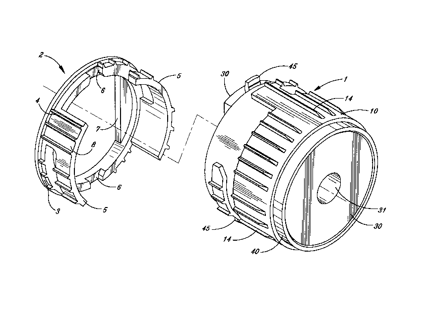
Fig. 1 is an isometric drawing showing the various
components of the present invention partially assembled;

- - 216~ 8~
Docket No. 2118-SL-SD
Fig. 2 is a front elevation of a faceplate according
to the present invention;
Fig. 3 is a top plan view of a faceplate according to
the present invention;
Fig. 4 is an isometric drawing showing the various
components of the present invention in fully assembled form;
Fig. 5 is a front elevation of the collar according to
the present invention, as viewed from the left of Fig. 6;
and
Fig. 6 is a side view of a collar according to the
present invention.
DETAILED DESCRIPTION
Referring to Fig. 1, which shows a partial assembly
isometric of a latch assembly according to the present
invention. The assembly is comprised of a front faceplate 2
comprised essentially of a flanged cylinder. The flange 3
is of a greater diameter than the hole in the door
preparation which accepts the assembly and the flange
effects a limit stop when the completed assembly is
installed. The face of the flange has an aperture or bore

-
~161850
Docket No. 2118-SL-SD
shaped to accept and through which the bolt member of a dead
bolt latch will move. The back of the front faceplate has a
number of recesses or notches 6 (typically but not limited
to two) into which a mating number of ears or lock tabs 45
on the deadbolt housing 40 will fit. According to the
present invention, the ears are bent up tabs or projections
45 formed on the cylindrical deadbolt housing 40.
A cylindrical portion 8 of the front faceplate 2
extends rearwardly, as best seen in Figs. 1 and 3. The
outside diameter of this portion is sized to fit the hole in
the door preparation. Ribs 4 on the outside of the
cylindrical portion 8 serve to locally increase the outside
diameter and interfere with the door hole. The inside
diameter is sized to slide over the cylindrical body of the
dead bolt housing 40. The cylindrical portion has "L"
shaped cutouts that produce a number of circumferentially
oriented lugs or fingers 5 (typically but not limited to the
two shown on Fig. 1).
As seen on Fig. 1, an essentially cylindrical collar
10 is provided having inside and outside diameters matching
and serving the same function as those of the cylindrical
portion of the front faceplate. Ribs 14 or other similar
protrusions on the outside of the collar 10 serve to locally
increase its outside diameter. The collar 10 also is

- ~161850
Docket No. 2118-SL-SD
provided with complimentary "L" shaped cutouts or fingers 15
(the same quantity as the front face) that provide mating
lugs for the front faceplate fingers 5.
A deadbolt 30 is reciprocally received within the
deadbolt housing 40 and protrudes through the bolt bore 7 in
the front faceplate 2. Projection of the deadbolt beyond
the front faceplate 2 provides the locking action of the
door lock or deadbolt as in the case of the present
embodiment. A bore 31 is provided to receive a hardened
cylindrical pin which acts to prevent the ready cutting of
the bolt 30 by means such as a hacksaw. The pin is not
shown.
Upon assembly, the components are oriented, as shown
in Fig. 1. The front faceplate 2 is assembled onto the
front of the deadbolt with the ears 45 on the deadbolt
housing 40 engaging in the recess or notches 6, and with the
bolt member 30 protruding through the front aperture 7. The
collar 10 is assembled onto the deadbolt housing 40 from the
side opposite the front faceplate. Axial motion engages the
two sets of lugs or fingers 5, 15, and a rotation of the
collar 10 locks the collar 10 to the front faceplate 2. The
deadbolt housing 40 and hence the dead bolt 30 reciprocally
disposed within the deadbolt housing 40 are thus retained by
the ears or lock tabs 45 between the rear of the front
faceplate 2 and the collar 10.

`~- 2161850
Docket No. 2118-SL-SD
The complete assembly is installed in the door
preparation (usually a circularly bored hole) by hammering
it in until the flange on the front face is flushed with the
edge of the door. The ribs 4, 14 on the front faceplate 2
and collar 10 respectively provide an interference fit with
the door preparation and prevent easy disassembly.
The use of a removable faceplate 2 allows greater
flexibility in the manufacturing process, reduces
inventories of completed latch assemblies, and allows the
end user greater flexibility since the style of faceplate
can be changed in the field to accommodate various
installation requirements.
While the invention has been described in terms of a
preferred embodiment for a deadbolt latch for illustration,
it should be obvious to one skilled in the art that the
invention is not limited to deadbolt configurations but will
also find use in conventional door knob latch units as well.
Having described the invention in terms of a preferred
embodiment, it should now be obvious to one skilled in
the art that the same may be varied in many ways without
departing from the scope and spirit of the invention. Any
and all such modifications are intended to be included
within the scope of the following claims:

Representative Drawing
A single figure which represents the drawing illustrating the invention.
Administrative Status

2024-08-01:As part of the Next Generation Patents (NGP) transition, the Canadian Patents Database (CPD) now contains a more detailed Event History, which replicates the Event Log of our new back-office solution.

Please note that "Inactive:" events refers to events no longer in use in our new back-office solution.

For a clearer understanding of the status of the application/patent presented on this page, the site Disclaimer , as well as the definitions for Patent , Event History , Maintenance Fee  and Payment History  should be consulted.

Event History

Description Date
Inactive: IPC from MCD 2006-03-12
Application Not Reinstated by Deadline 2004-11-01
Time Limit for Reversal Expired 2004-11-01
Deemed Abandoned - Failure to Respond to Maintenance Fee Notice 2003-10-31
Letter Sent 2002-09-20
Inactive: Status info is complete as of Log entry date 2002-09-20
Inactive: Application prosecuted on TS as of Log entry date 2002-09-20
Request for Examination Requirements Determined Compliant 2002-09-03
All Requirements for Examination Determined Compliant 2002-09-03
Application Published (Open to Public Inspection) 1996-05-05

Abandonment History

Abandonment Date Reason Reinstatement Date
2003-10-31

Maintenance Fee

The last payment was received on 2002-10-04

Note : If the full payment has not been received on or before the date indicated, a further fee may be required which may be one of the following

  • the reinstatement fee;
  • the late payment fee; or
  • additional fee to reverse deemed expiry.

Please refer to the CIPO Patent Fees web page to see all current fee amounts.

Fee History

Fee Type Anniversary Year Due Date Paid Date
MF (application, 2nd anniv.) - standard 02 1997-10-31 1997-10-08
MF (application, 3rd anniv.) - standard 03 1998-11-02 1998-10-16
MF (application, 4th anniv.) - standard 04 1999-11-01 1999-10-15
MF (application, 5th anniv.) - standard 05 2000-10-31 2000-10-13
MF (application, 6th anniv.) - standard 06 2001-10-31 2001-10-05
Request for examination - standard 2002-09-03
MF (application, 7th anniv.) - standard 07 2002-10-31 2002-10-04
Owners on Record

Note: Records showing the ownership history in alphabetical order.

Current Owners on Record
SCHLAGE LOCK COMPANY
Past Owners on Record
L. C. DEREK CHAMBERLAIN
Past Owners that do not appear in the "Owners on Record" listing will appear in other documentation within the application.
Documents

To view selected files, please enter reCAPTCHA code :


To view images, click a link in the Document Description column. To download the documents, select one or more checkboxes in the first column and then click the "Download Selected in PDF format (Zip Archive)" or the "Download Selected as Single PDF" button.

List of published and non-published patent-specific documents on the CPD .

If you have any difficulty accessing content, you can call the Client Service Centre at 1-866-997-1936 or send them an e-mail at CIPO Client Service Centre.


Document
Description 
Date
(yyyy-mm-dd) 
Number of pages   Size of Image (KB) 
Representative drawing 1999-08-04 1 41
Cover Page 1995-10-31 1 14
Description 1995-10-31 6 202
Abstract 1995-10-31 1 13
Claims 1995-10-31 3 87
Drawings 1995-10-31 3 93
Reminder of maintenance fee due 1997-07-01 1 111
Reminder - Request for Examination 2002-07-03 1 127
Acknowledgement of Request for Examination 2002-09-20 1 177
Courtesy - Abandonment Letter (Maintenance Fee) 2003-12-29 1 177