Language selection

Search

Patent 2161879 Summary

Third-party information liability

Some of the information on this Web page has been provided by external sources. The Government of Canada is not responsible for the accuracy, reliability or currency of the information supplied by external sources. Users wishing to rely upon this information should consult directly with the source of the information. Content provided by external sources is not subject to official languages, privacy and accessibility requirements.

Claims and Abstract availability

Any discrepancies in the text and image of the Claims and Abstract are due to differing posting times. Text of the Claims and Abstract are posted:

  • At the time the application is open to public inspection;
  • At the time of issue of the patent (grant).
(12) Patent: (11) CA 2161879
(54) English Title: CHAIR
(54) French Title: CHAISE
Status: Expired and beyond the Period of Reversal
Bibliographic Data
(51) International Patent Classification (IPC):
  • A47C 3/021 (2006.01)
  • A47C 1/032 (2006.01)
(72) Inventors :
  • DESANTA, SIMON (Germany)
(73) Owners :
  • F.-MARTIN STEIFENSAND BUEROMOEBEL GMBH
(71) Applicants :
  • F.-MARTIN STEIFENSAND BUEROMOEBEL GMBH (Germany)
(74) Agent: KIRBY EADES GALE BAKER
(74) Associate agent:
(45) Issued: 1999-09-07
(86) PCT Filing Date: 1995-03-24
(87) Open to Public Inspection: 1995-10-05
Examination requested: 1996-01-17
Availability of licence: N/A
Dedicated to the Public: N/A
(25) Language of filing: English

Patent Cooperation Treaty (PCT): Yes
(86) PCT Filing Number: PCT/EP1995/001126
(87) International Publication Number: WO 1995026152
(85) National Entry: 1995-10-31

(30) Application Priority Data:
Application No. Country/Territory Date
P 44 10 383.2 (Germany) 1994-03-25

Abstracts

English Abstract


A chair with a moveable seat panel (12) mounted springingly on a support (10) and a back-rest
(14) has a seat panel made from pliant panel material which is guided down around the front
edge (20) of the seat panel in a U-shape and then rigidly sandwiched in the support (10). A
guide bar (24) which is pivotably mounted on the support (10) is directed backwards and is
rigidly connected with the underside of the rear end portion of the seat panel (12)


French Abstract

Une chaise avec un siège (12) mobile, élastiquement soutenu sur un bâti (10), et un dossier (14) comprend un siège constitué d'une plaque en un matériau flexible recourbée en U vers le bas au bord antérieur (20) du siège et fixée au bâti (10). Un bras (24) monté pivotant sur le bâti (10) s'étend en arrière et est fixé à la face inférieure de la zone terminale postérieure du siège (12).

Claims

Note: Claims are shown in the official language in which they were submitted.

-4-
CLAIMS
1. A chair comprising:
a resilient seat panel mounted on top of a support;
a back-rest located at a rear portion of the seat panel, the seat panel being
made from thin,
pliant panel material, the material being guided down around a front edge of
the seat panel
in a U-shape and being rigidly attached to the support; and
at least one guide bar having one end pivotably mounted at the support so that
the guide bar
can pivot about a fixed stationary axis located at the support, said guide bar
being directed
backwards from the support and having a second end rigidly attached with an
underside of
the seat panel in the rear portion thereof, said guide bar causing said seat
panel to flex into
a desired shape when a user sits on the chair.
2. The chair of claim 1, further comprising a guide device connected with the
second end
of the guide bar, the back-rest being essentially vertically displaceably
accommodated in the
guide device.
3. The chair of claim 1, wherein the panel material of the seat panel is sub-
divided into
a plurality of parallel strips by parallel grooves running in the forwards-
backwards direction
of the chair.
4. The chair of claim 1, wherein the back-rest is made from pliant panel
material.
5. The chair of claim 4, wherein the panel material of the back-rest is sub-
divided into
a plurality of parallel strips by parallel, vertical grooves.
6. The chair of claim 1, wherein the panel material of the seat panel is made
from
plywood or plastic.

-5-
7. The chair of claim 6, wherein the panel material of the back-rest is made
from
plywood or plastic.
8. A chair comprising:
a support extending generally in a vertical direction;
a seat having a front portion and a rear portion, and being resiliently
mounted on said support,
said seat being composed of a thin, pliant material, and having:
a lower, essentially horizontal panel rigidly attached to said support; and
an upper, essentially horizontal panel located above said support and being
contiguously
connected to said lower panel along the front portion of said seat to form a U-
shape; and
at least one guide bar having a first end pivotably connected to said support
so that the guide
bar can pivot about a fixed stationary axis located at the support, and a
second end rigidly
connected to an underside of said upper panel in the rear portion of said
seat, said guide bar
causing said seat to flex into a desired shape when a user sits on the
chair.
9. The chair defined in claim 8, further comprising a back-rest located at the
rear portion
of said seat.
10. The chair defined in claim 8, further comprising a guide device attached
to the second
end of said guide bar, and a back-rest vertically displaceably accommodated in
said guide
device.

Description

Note: Descriptions are shown in the official language in which they were submitted.


21618'9
- 1-
CHAIR
The invention relates to a chair with a moveable seat panel mounted
springingly on a support,
and a back-rest.
Over the last few years, office chairs have been developed to a high level
with respect to
functionality, ergonomic characteristics and durability. Naturally, this has
resulted in ever more
complicated, heavier and also more expensive constructions.
The task of this invention is to create a simple, light chair which is
inexpensive to manufacture
and, despite being of a simpler construction, provides comfortable seating
whilst meeting
ergonomic requirements.
According to the invention, this task is solved for a chair of the above-
mentioned type in that
the seat panel is made from thin, pliant panel material which is guided down
around the front
edge of the seat panel in a U-shape and then rigidly sandwiched in the
support.
Plywood or various plastic materials could, for example, be used for this type
of pliant, flexible
2o panel material.
As an additional guide for the seat panel it is useful to provide, between the
rear portion
thereof and the support, at least one guide bar that is pivotably connected
with the support and
rigidly connected to the underside of the rear portion of the seat panel, and
which causes the
rear portion of the seat panel to flex into position along a pre-determined
path, and, when the
seat panel flexes into position, forces it into an essentially S-shaped bend,
which results in an
ergonomically advantageous adaptation to the user's body shape.
The back-rest is also preferably made from a flexible, panel-shaped material.
It is preferably
3o connected with the rear end of the seat panel.
A guide allowing the back-rest to be vertically adjusted is preferably mounted
at the rear end of
the guide bar.
1

CA 02161879 1999-O1-18
-1 a-
In accordance with one aspect of the present invention there is provided a
chair comprising:
a resilient seat panel mounted on top of a support; a back-rest located at a
rear portion of the
seat panel, the seat panel being made from thin, pliant panel material, the
material being
guided down around a front edge of the seat panel in a U-shape and being
rigidly attached
to the support; and at least one guide bar having one end pivotably mounted at
the support
so that the guide bar can pivot about a fixed stationary axis located at the
support, said guide
bar being directed backwards from the support and having a second end rigidly
attached with
an underside of the seat panel in the rear portion thereof, said guide bar
causing said seat
panel to flex into a desired shape when a user sits on the chair.

_2_ 2~61$'~9
Preferred embodiments of the invention will be described in more detail below
with reference
to the enclosed drawings, in which
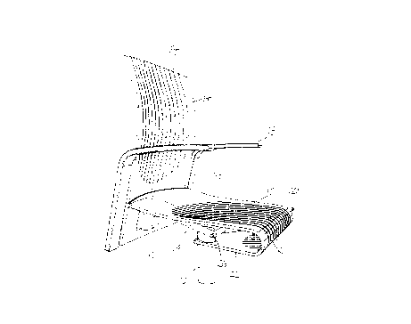
Fig. 1 is a perspective diagrammatic partial view of a chair according to the
invention;
Fig. 2 is a corresponding diagrammatic partial side view.
Fig. 1 shows a chair according to the invention, with a vertical pillar 10
forming the support,
1o with a rotating base at the bottom end (not shown), a seat panel 12 and a
back-rest 14, as well
as two arm-rests 16 and 18. A different support, e. g. a support with four
legs, can be used
instead of the pillar 10.
The seat panel 12 is made from a thin, pliant panel material which is bent
down in a U-shape
around the front edge, designated by the figure 20, of the seat panel 12, and
is rigidly
sandwiched in the top portion of the pillar 10 with its lower, now again
rearwardly directed
section 22. This results in a strong, but - thanks to the flexibility of the
panel material of seat
panel 12 - springingly pliant mounting for the seat panel 12 when the chair is
used by one
person.
To additionally support and guide the seat panel 12, the example illustrated
shows two parallel
guide bars 24 which are pivotably mounted in an axle 26 at the top end of the
pillar 10 and
from there are slopingly inclined backwards and upwards. These guide bars 24
are rigidly
attached underneath the rear end portion of the seat panel I2, as shown more
precisely in Fig.
2. This ensures that the rear end of the seat panel 12 is accurately guided as
its flexes into
position, and furthermore, when it flexes into position, the seat panel 12 is
also forced by the
rigid connection with the guide bars 24 into an essentially S-shaped bend
which has been
shown to be very ergonomically and anatomically advantageous. This S-shaped
bend is based
on the fact that when the guide bars 24 move downwards, at least the rear edge
portion of the
3o seat panel always runs parallel to the guide bars and therefore, in the
rearwardly lowered
position, the panel only rises in the centre portion in an S-shape towards the
level of the front
edge.

CA 02161879 1999-O1-18
-3-
Fig. 2 indicates connecting mountings 28, which rigidly connect the guide bars
24 to the rear
end portion of the seat panel 12 over a certain length.
Rigidly connected to these mountings 28 respective the rear end of the guide
bars 24, there
is also a vertical guide device 30, which vertically displaceably accommodates
the back-rest
14, so that the height of the back-rest 14 can be separately adjusted. This
allows the height
of the chair user to be taken into account.
To improve flexibility, the panel-shaped material of the seat panel 12 and
also of the back-rest
14, which can be made from, for example, plywood or a suitable, appropriately
flexible
plastic, can be sub-divided into individual, parallel strips (not shown) by a
plurality of grooves
32,34 contrived in the longitudinal, i.e. vertical direction of the chair.
This strip formation
immediately increases the flexibility in the lateral direction of the seat
panel 12 and back-rest
14, therefore improving the adaptation to the user's body form.
The invention makes it possible to use the inherent elasticity of the panel
material, particularly
of a plywood panel, not just in the direct area of the seat panel, but more
broadly, in the
manner of a spring. Thus a chair mechanism is created that meets the usual
requirements with
regard to seating comfort and adjustment options, which functions without
using a single extra
spring. Relatively simple, inexpensive chairs with a high level of user
comfort can also be
manufactured.

Representative Drawing
A single figure which represents the drawing illustrating the invention.
Administrative Status

2024-08-01:As part of the Next Generation Patents (NGP) transition, the Canadian Patents Database (CPD) now contains a more detailed Event History, which replicates the Event Log of our new back-office solution.

Please note that "Inactive:" events refers to events no longer in use in our new back-office solution.

For a clearer understanding of the status of the application/patent presented on this page, the site Disclaimer , as well as the definitions for Patent , Event History , Maintenance Fee  and Payment History  should be consulted.

Event History

Description Date
Time Limit for Reversal Expired 2005-03-24
Letter Sent 2004-03-24
Inactive: Correspondence - Transfer 2003-07-22
Inactive: Correspondence - Formalities 2003-07-22
Letter Sent 2003-05-13
Inactive: Single transfer 2003-03-20
Inactive: Entity size changed 2002-03-21
Grant by Issuance 1999-09-07
Inactive: Cover page published 1999-09-06
Pre-grant 1999-06-02
Inactive: Final fee received 1999-06-02
Letter Sent 1999-03-24
Notice of Allowance is Issued 1999-03-24
Inactive: Approved for allowance (AFA) 1999-03-10
Amendment Received - Voluntary Amendment 1999-01-18
Inactive: S.30(2) Rules - Examiner requisition 1998-07-17
Inactive: Status info is complete as of Log entry date 1998-03-30
Inactive: Application prosecuted on TS as of Log entry date 1998-03-30
All Requirements for Examination Determined Compliant 1996-01-17
Request for Examination Requirements Determined Compliant 1996-01-17
Application Published (Open to Public Inspection) 1995-10-05

Abandonment History

There is no abandonment history.

Maintenance Fee

The last payment was received on 1999-03-01

Note : If the full payment has not been received on or before the date indicated, a further fee may be required which may be one of the following

  • the reinstatement fee;
  • the late payment fee; or
  • additional fee to reverse deemed expiry.

Please refer to the CIPO Patent Fees web page to see all current fee amounts.

Fee History

Fee Type Anniversary Year Due Date Paid Date
Request for examination - small 1996-01-17
MF (application, 3rd anniv.) - small 03 1998-03-24 1998-03-03
MF (application, 4th anniv.) - small 04 1999-03-24 1999-03-01
Final fee - small 1999-06-02
MF (patent, 5th anniv.) - small 2000-03-24 2000-03-02
MF (patent, 6th anniv.) - small 2001-03-26 2001-03-09
MF (patent, 7th anniv.) - standard 2002-03-25 2002-03-12
MF (patent, 8th anniv.) - standard 2003-03-24 2003-02-28
Registration of a document 2003-03-20
Owners on Record

Note: Records showing the ownership history in alphabetical order.

Current Owners on Record
F.-MARTIN STEIFENSAND BUEROMOEBEL GMBH
Past Owners on Record
SIMON DESANTA
Past Owners that do not appear in the "Owners on Record" listing will appear in other documentation within the application.
Documents

To view selected files, please enter reCAPTCHA code :


To view images, click a link in the Document Description column. To download the documents, select one or more checkboxes in the first column and then click the "Download Selected in PDF format (Zip Archive)" or the "Download Selected as Single PDF" button.

List of published and non-published patent-specific documents on the CPD .

If you have any difficulty accessing content, you can call the Client Service Centre at 1-866-997-1936 or send them an e-mail at CIPO Client Service Centre.


Document
Description 
Date
(yyyy-mm-dd) 
Number of pages   Size of Image (KB) 
Drawings 1995-10-05 2 38
Claims 1995-10-05 1 37
Description 1999-01-18 4 146
Claims 1999-01-18 2 66
Cover Page 1996-03-19 1 16
Abstract 1995-10-05 1 12
Description 1995-10-05 3 125
Cover Page 1999-08-31 1 39
Representative drawing 1999-08-31 1 13
Representative drawing 1999-06-01 1 24
Commissioner's Notice - Application Found Allowable 1999-03-24 1 164
Courtesy - Certificate of registration (related document(s)) 2003-05-13 1 106
Maintenance Fee Notice 2004-05-19 1 173
Courtesy - Certificate of registration (related document(s)) 2003-05-13 1 106
Correspondence 2003-07-22 1 59
PCT 1995-10-31 9 320
Correspondence 1999-06-02 1 38
Fees 1997-03-17 1 20
Fees 1997-03-17 1 48