Note: Descriptions are shown in the official language in which they were submitted.
21 62065
MF,TT-TOl) OF !~T~,PARATlN(~T PRF,nF,TF,RMlNF,n ~T(~TNAI, (~OMPONh,NT.
FR()M WTRF,T,TNh, A(~OTJ~TIl~ ARRAY R(~ T nATA
RA~,T~I~TROIJNl) ()F TT~, TNVh,NTTl)N
L Fiel~ ~f thP Tnventinn
The present invention is related to the field of electric wireline wellbore logging
tools. More s~ecirlcally, the present invention is related to a method of processing data
from a plurality of acoustic sensors in an electric wireline tool to dclclllli~e acoustic
wave tranemiesion plupellies in an earth formation pcllcLI~ted by a wellbore.
T~ie~lleeion of th~ ~Pl~tPfl Art
Electric wireline logging tools include various types of acoustic logging
instruments. Acoustic logging instruments are used, among other things, for
~le~ the velocities at which acoustic waves propagate through earth formations.
Acoustic waves can propagate through a particular earth formation at several dirr~,lc
velocities depclldillg on the mode of propagation of the acoustic waves.
Two acuu~lic wave pl~ inn modes of particular interest in evaluation of earth
formations are colll~lessional and shear. Colllplcssional propagation takes the form of
~ltPrn~e cOlll~ ssions and rarefactions of the formation. The direction of propagation
of compressional waves is in the same plane as the motion of the particles of the
fo~n~tion Shear wave plul)agalion colll~flses particle motion oc~;ullmg at right angles
to the direction of propagation. Shear waves typically cannot travel through fluids.
Measulclllent of shear velocities by typical well logging tools requires a conversion of
the wave propagation mode of acoustic energy emitted by the tool intû shear waves in
the formation. Shear waves can be gellcl~ted at the wellbore wall for example, when
cullll~ressional energy strikes the wall.
21 62065
Acoustic logging tools typically include acoustic energy sources and receivers
combined in a single hL~Ll~ll~nl. An acoustic measurement is made first by a~;liv~thlg
the source so that acoustic energy radiates into the wellbore, refracts at the wellbore wall
so that it propagates along the wellbore wall, and then re-refracts into the wellbore so
that the acoustic energy can be detected by at least one receiver disposed in the
instrument. Refraction of the energy so that it travels along the wellbore wall is a result
of typical acoustic velocity contrasts between the formation and fluid filling the
wellbore.
Acoustic logging il~ elll~ known in the art include monopole devices, which
have acoustic energy sources, or l. ~n~ , that approximate a point source of energy
mP~ning that acoustic energy radiates away from the Ll,.~ er subst~nti~lly as if the
energy came from a single point. Monopole devices are used for determinin~ the
velocities of acoustic waves which propagate in certain specific propagation modes such
as col"~lessional and Stoneley modes. In earth formations having shear wave velocities
e~ the ~lll~reSSiOllal velocity of the fluid in the wellbore, monopole devices can
also be used to measure the velocity of shear wave propagation because the shear waves
will also refract so as to propagate along the wellbore wall.
Also known in the art are dipole h~L~ ,ents which del~""hle velocities of
acoustic waves prop~g~ting in a flexural mode. Dipole instruments can be used todelel,nille shear wave velocities when the earth formation has a shear wave velocity
lower than the co~ r~ssional velocity of the fluid filling the wellbore, in which case
colll~l~ssional energy from the monopole l~n~.--il~el, which collv~lL~ to shear energy at
the wellbore wall, usually cannot be detected by the receivers in the instrument because
the shear waves are l~rld~Led out into the formation rather than along the wellbore wall.
In order to overcome this limitation, the Lli~ rl in a dipole h~Ll~l,llelll usually
col~lises a "bender bar" or similar type ll~.-~..lill~ l which creates lln~llll~tions in the
fluid in the wellbore. Undulations can be described as a tl~ se motion of the
particles in a material being e~ gi~d, in which a portion of the material moves in one
direction, and another portion of the m~t~ri~l di~laced along a central axis of the bender
bar moves in the opposite direction. The particle motion is perpendicular to the
- 21 62065
direction of wave propagation, as it is with shear wave propagation. The llnrlnl~tions
in the wellbore fluid ge~ similar lm~ tions in the wall of the wellbore, which
propagate along the wellbore wall subst~nti~lly at the shear velocity of the formation.
Monopole and dipole ill~illUlllt~ can be combined in a single tool. For example,"The Multipole Array Acoustilog", Atlas Wireline Services, Houston, TX, 1991,
describes a combination monopole/dipole tool.
Typically, the combination tool collll"ises at least one monopole ll~ er, at
least one dipole Ll~ el, and a plurality of receivers at spaced apart locations along
a tool housing. The l1An~ e~S~ lcceiv~l~ and housing can be designed to minimi7.e
detection of waves propag~ting in ullwallled modes during a mea~ulclllelll cycle for a
particular wave prop~g~tion mode. For example, "The Multipole Array Acoustilog" tool
comprises dipole receivers which are highly sensilive to the lln~ tions~ or flexural
waves, but tend to reject detection of waves ll~ led through the wellbore fluid as
monopole colll~lessions; and the tool also co~ "ises monopole receivers which are
highly sensilivc to colll~,cssional waves.
The dipole rcceive,s are designed to gel1e,ale a large output signal, only in
response to flexural waves, because residual components of waves propag~ting in
monopole type modes can be time coincident at the ,~ceiv~ with the flexural waves.
Dipole receiver hlsellsilivily to the monopole wave components reduces the amplitudes
of the monopole wave components in the dipole receiver output. It is thelcfolc easier
to make measurements from the flexural waves.
Velocity of wave propagation is typically delellllilled by calclll~tin~ the amount
of time elapsed between co"c~onding detections of a wave by each receiver in a
plurality of receivers at spaced apart locations along the instrument. The ~lict~n~ e
belween each of the receivers is known, so the velocity can be c~lrlll~ted directly from
the elapsed time dcl. lll~illed belweell detections of the wave at the corresponding
receivers.
The time dirrelellce between detections at corresponding receivers can be
d~ t~ d by a method known as semblance correlation. The output of each receiver
resulting from the detection of a wave typically comprises an electrical signal
2 1 62065
representing acoustic amplitude. The signal can be ~igiti7e~ into a series of numbers
which l~lcsclll samples of the signal taken at spaced apart time intervals. The ~1igiti7ing
can be done either by circuits in the h~ lclll, or by equipment located at the earth' s
surface. The samples can then be processed by e~lui~lllclll typically located at the earth' s
surface. A time window can be chosen by the tool operator, typically by visually~x~ g a graphic lc~lescl~ion of the signals to delclll,hle a time span during which
the signal appears to have sufficient amplitude. Within the chosen time window, the
signal from each receiver is then correlated with signals from the other lccei~ L~, and
the time dirrclci~ce bclwæn signals which yields the highest correlation value, or degree
of correspondence, is dc~lmhled to be the time dirrelellce bclwccul wave detection at
each rcceiver. The time dirr~ lellce is used to calculate the velocity directly since the
~i.c~nr~ between lcceivcls is known.
Semblance correlation processing can be difficult because acoustic wave
propagation modes other than com~lcssional and flexural occur in the wellbore as a
result of excitation of the wellbore wall by the energy radiated from the ll,l~ cl~.
These other propagation modes may create waves which hllclrclc with identifi~ation of
the desired wave mode in the receiver signal. For example, propagation modes such as
Stoneley waves and pseudo-Rayleigh waves propagate within a wellbore along the
intorf~re bclwæn the liquid filling the wellbore and the wellbore wall. "Vertical Seismic
Profiling", by Bob A. Hardage, Geophysical Press, London, 1985, describes the
Stoneley and pseudo-Rayleigh propagation modes (pp. 75-76). The hllelÇe,c,1ce created
by Stoneley and pseudo-Rayleigh waves can be particularly ~liffl~l~lt to resolve if the
Stoneley and pseudo-Rayleigh waves have very high amplitudes or if parts of the
Stoneley and pseudo-Rayleigh waves are time coincident with the flexural or
colllprcssional waves.
It is known in the art to separate dirr~cllL wave pr~L~agalion mode waves by using
frequency b~n lp~s filters. For example, the Stoneley wave components which can be
present in a monopole receiver signal typically have a high amplitude in a much lower
frequency range than colllLlc~ al waves occullillg in the same signal. Application of
a high-pass filter to the Icceivel signal can ~ the Stoneley wave colllpol1elll of the
- 21 62065
receiver signal.
Frequency b~ s filt~rin~ reduces the bandwidth of the isolated mode signal,
which can make the data from the isolated mode signal less useful, particularly if the
earth formation is di~clsive, that is, the formation has velocities which are frequency
S dependent. Frequency ban-lp~s filtering is also relatively hlerrcclive if there is
substantial frequency coincidence between the desired wave mode and the ullw~ullcd
wave mode. Frequency coincidence typically occurs in dipole receiver signals, where
the flexural and Stoneley waves can have substantial overlap in their respectivefrequency contents.
The ~,k) filter is som~-tim~s used in geophysical exploration for procescing
vertical seismic profile (VSP) surveys, and for proces~in~ surface seismic surveys. The
~,k) fhter is used to remove acoustic energy propagating in an undesired direction. For
e~ le, in a VSP survey, so-called U~gOill~ waves, which reflect from seismic events
deeper than a borehole geophone deployed in the wellbore, can be separated from so-
called d )wl~ohlg waves, which reach the borehole geophone directly through the earth
from a seismic source at the earth's surface, by use of the ~,k) filter. The ~,k) filter is
also used in surface seismic surveys to atteml~te multiple reflections caused by seismic
reflectors near the earth's surface, or by the water surface in a marine seismic survey.
For example, "Vertical Seismic Profiling" (pp 174-181) describes the process of ~,k)
filtering as related to VSP data.
The ~,k) filter is .liffi~.lllt to use on seismic data, however, because
transformation of data in the time-position domain, which is how the seismic or VSP
data are recorded, into the frequency-wavenumber (or f,k) domain requires uniformly
spaced data samples in both time and position in order for the filter to work without
dislollillg the results. Control of the interval between sample depths in VSP data or of
the geophone locations in surface seismic data can be inadequate to plcvclll distortions
of the data on ll~l~ro",lation to the ~,k) domain. Con~equently, ~,k) filtering has
generally been replaced in the art by other m~tho~ls. For example, "Seismic DataProcessin~", by Ozdogan Yilmaz, Society of Exploration Geophysicists, Tulsa, 1987,
(pp. 68-73, 79) describes the limitations of ~,k) filtering.
21 62065
~IJMMARY OF TT-TF, TNVF,NTT()N
The present invention is a metbod of sepald~ a component of an acoustic wave
propag~ting in a predele. .~ d mode from data recorded by a wireline acoustic array
logging tool. The data from a plurality of spaced-apart receivers in the acoustic logging
tool are collvel~ed from time-domain waveforms by a 2-dim.on~ional Fourier transform
into data in the frequency-wavenumber, or (f,k) domain. A velocity b~n-lp~s filter is
applied to the 6~,k) converted data, and the filtered data are reconverted to the time
domain.
In a particular embodiment of the invention, the velocity filtered time domain
data are semblance coll~,ldtcd to ~r~lllillP the time dirrclcilce b~lween detections of the
component of the wave prop~g~ting in the predtlcllllilled mode at corresponding
receivers. Values of colll~lessional and flexural velocity are calc~ ted from the time
dirr~ ces so d~l~.",i,l~d.
RRT~,F nT'',~l~,RTT'TT()N OF TT~, T)RAWTN(~T~
Figure 1 shows an acoustic array logging tool disposed within a wellbore.
Figure 2 shows a graphic lc~lcsell~tion of signals gen~l~led by lcceivels in thetool.
Figure 3 shows the pl~cem~nt of tr~n~mitters and receivers on the tool in more
detail.
Figure 4 shows a flow chart of the processing steps pelrolllled on the receiver
signals according to the present invention.
Figure 5 shows a graphic display of signals from the plurality of receivers before
filtering by the method of the present invention.
Figure 6 shows a graphic rcpl~csel~ ion of a combined correlogram generated
from the receiver signals before filtering by the method of the present invention.
Figure 7 is a graphic lc~lcsellktlion of the amplitude of the signals in Figure 5
after conversion to thef,k domain.
- 21 62065
Figure 8 is a contour graph of the same data as shown in Figure 7, the contour
graph also having bo~ln-l~rie of a velocity filter to be applied according to the present
invention.
Figure 9 shows the data as p~sellled in Figure 7 after application of the filterS according to the present invention.
Figure 10 shows the data as displayed in Figure 8 after application of the filter
according to the present invention.
Figure 11 shows the filtered data of Figure 10 after application of an inverse 2-D
Fast Fourier transform.
Figure 12 shows a graphic r~resenlalion of a combined correlogram ge~ dt~d
from the filtered data shown in Figure 11.
nF~(~Rn"rTON OF THF PRFhl~RRFl) F,MR()l)~MF,NT
Figure 1 is a simplified illustration of an acoustic array well logging tool 2
showing how the tool 2 is typically used in a wellbore 10 pell~ hlg an earth formation
12. The tool 2 comprises at least one ll~ 14 and a plurality of receivers 16
positioned at spaced apart locations along the tool 10. The tool 2 is lowered into the
wellbore 10 by means of a cable 8 COlllpliSillg at least one in~ ted electrical conductor
(not shown). The cable 8 is lowered into the wellbore 10 by means of a surface logging
unit 4. The surface unit 4 typically colll~fi~s winch e~lui~ llL 4A for moving the cable
8 into and out of the wellbore 10, and a colll~u~ 4B for receiving and proces~ing
signals (not shown) ll~ "~ by the tool 2 to the Colll~ult~l 4B along the cable 8.
Periodically the at least one llol~ l 14 is ellelgi~d to emit acoustic energy
pulses 18 which travel through a fluid 6 filling the wellbore 10 until they reach the wall
of the wellbore 10. The pulses 18 then interact with the wall of wellbore 10. Interaction
of the acoustic energy pulses 18 with the wall of the wellbore 10 causes modified
acoustic energy waves to travel along the wall of the wellbore 10, and eventually enables
the modified acoustic waves 18 to reach the receivers 16 in the tool 2. The receivers 16
gel~ld~ e1e~trir~1 signals (not shown) which correspond to the amplitude of the further
-- 2 1 62065
modified acoustic pulses 18 which reach each of the receivers 16.
Illru~ aLion about acuuxlic plu~llies of the earth formatiûn 12 can be del~llnilled
by procesxing the signals generated by the receivers 16 in the colll~ul~l 4B, as will be
explained in more detail.
A graphic lep~ ;.lion of the signals gellelaLed by the receivers 16 is shown in
Figure 2. The graph in Figure 2 has time on the cooldillate axis and signal amplitude
corresponding to each waveform 20 on the or~ dte axis. Signals from each of the
receivers 16 are shown as individual waverûlllls 20. Each waveform 20 corresponds to
one of the receivers 16. The wavefolllls 20 can include an indication of the time of
activation ûf the ll,.l.x.. ill~. (shown in Figure 1 as 14) as shown generally at 22. The
waveforms 20 are also typically cl~1e. ;~r~ by a time interval, shown generally at 24,
having low signal level which occurs prior to detection of acoustic energy allivhlg from
the wellbore 10 wall. Acoustic energy which arrives at the receivers 16 from thewellbore 10 wall, is generally shown at 26. Chara~ lics of the signals resnlting from
~etçctinn of the acoustic energy, as shown at 26, depend on the type of energy imparted
by the ll~ x~ ,r 14, the type of receiver (shown as 16 in Figure 1), and the acoustic
tranxmixsion properties of the earth formation (shown as 12 in Figure 1).
Figure 3 shows the configuration of the tool 2 in greater detail. The upper partof the tool 2 culllplises at least one monopole Ll~nx...illç~ 32 and at least one dipole
L1AIIXIII;~ 34. The monopole Ll~.~x.. ill~. 32 emits pulses of acoustic energy (shown as
18 in Figure 1) which interact with the fluid 6 filling the wellbore 10 subst~nti~lly as a
point source of energy. Acoustic waves em~n~ting from the monopole Ll;~x~ lel 32consist of subst~nti~lly spherically ra li~ting colll~ ,;,xions and rarefactions of the fluid
6 in the wellbore 10. The dipole ll,.l~x...illçr 34 cùlll~lises a bender bar having two
active ends 35, 37. The dipole ll~llxll~ . 34 gellelaLes acoustic waves (also shown as
18 in Figure 1) which interact with the fluid 6 filling the wellbore 10 in the form
n~l-ll~tions of the fluid 6. The nnt~ tions comprise back-and forth motion along a
subst~nti~lly straight-line path having a wavelength roughly equal to the ~lixt~nre
sepalalillg the ends 35, 37 of the dipole ll,..~ er 34. The lln~ tions in the fluid 6
interact with the wall of the wellbore 10 to gellelate similar ~m~ tions in the wall of
~ 21 62065
the wellbore 10. The ln~ tions imparted to the wellbore 10 wall travel along the
wellbore 10 wall subst~nti~lly at the shear velocity of the earth formation 12.
Direct coupling of acoustic energy from the ll~.n~ 32, 34 to receivers 31,
33 located near the bottom of the tool 2 is substantially reduced by an acoustic isolator
38 interposed between the ll~ c,~ 32, 34 and lcceivcl~ 31, 33.
The tool 2 typically colll~lises two types of receivers as shown at 31 and 33.
One type of receiver is a monopole receiver as shown at 33. The monopole receivers
33 respond to colll~lessions and rarefactions of the fluid 6 in the wellbore 10 which
strike the receivers 33 from all directions ~imlllt~n~ously. Wave propagation modes
which can be detected by the monopole receivers 33 include colllplcssional mode,refracted shear mode gellclaLcd by interaction of the wellbore 10 wall with
colll~l~ssional energy from the monopole L-1A~ 32, and Stoneley mode. Dipole
receivers, shown at 31, are responsive to unidirectional motion of the fluid 6 in the
wellbore, and ~lcl~ fole are particularly sensitive to the un~ tions travelling along the
wall of the wellbore 10 which are in~ ced by the dipole Ll,l"~"~ er 34. The dipole
Ll,..l~lllilll ~ 34 and lcceivcrs 31 are typically used to measure flexural and shear velocity,
particularly when the flexural velocity of the formation 12 is slower than the
compressional velocity of the fluid 6 in the wellbore so that making refMctive shear
velocity measurements would be impossible. The dipole receivers 31 are relatively
insensitive to omnidirectional ples~ul'c variations in the fluid 6, and Lllclerorc
substantially reject detection of colllylessional waves in the fluid 6 in the wellbore 10.
The dipole l~CiVCl~ 31 do not entirely reject detection of colllplcssional energy, as will
be further explained.
In Figure 5, vvav~rulllls 61-68 from the dipole receivers (shown as 31 in Figure3) exhibit both flexural components 81-88 and residual colllplcssional colllpoll~nL~ 71-78
prior to proces~ing by the method of the present invention. In the w~vcfollll
representing the receiver 31 most distant from the 11;1II~ ;L~eI- 34, as shown at 68, the
- residual com~,cssiollal cc,llll)ollelll 78 does not illLclçel`c with the flexural component 88,
~ i"~ lly bPcause of the relatively low flexural velocity and the long ~ t~nre between
the tr~n~mi~ter 34 and that particular receiver 31. S~lbst~nti~l hlLclrclcll~e between
- 21 62065
flexural 81 and co~ essional 71 components occurs in the waveform 61 lcp~se~ g
the receiver 31 nearest the ~ ",ill~l 34 because of the much shorter Ll~ iL~er to
receiver di~t~nre. Varying amounts of hllelr~ lce occurs in the other waveforms 62-
67.
A combined correlogram curve gel1eIaLed from the w~vefolllls 61-68 of Figure
5 is shown in Figure 6 at 90. The curve 90 in~lir~tPs the degree of coll.,s~olldence
between the waverolllls 61-68 at various values of time delay bclween individualreceivers 31, the time delay c~llc~olxli~g inversely to acoustic velocity in the formation
12.
Rer~ e residual ~lll~lcssional colll~ollellL~ 71-78 are present in the waveforms61-68, the correlation curve 90 exhibits velocity peaks at 91 and 92. In certain cases the
peaks can be subst~nti~lly coincident in velocity or can have reversed relative
amplitudes, making flexuMl velocity delt;llnil~lion .lifflcult
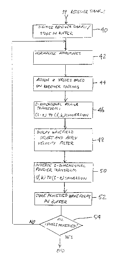
Figure 4 shows the process steps of the present invention in more detail.
Receiver signals 39 are ~igiti7P,d as shown at 40. The signals 39 are typically digiti7P,d
in the tool 2 and LlA~ ed to the surface unit 4 for storage in a buffer.
Processing steps following digiti7~tion of the signals typically take place in the
colll~ulel 4B forming part of the surface unit.
The digiti7~d signals are then processed to equ~li7P signal amplitudes between
lcceivcl~ 31 by nonn~li7ing the signals as shown at 42. As shown at 44, Lu~ iLler to
receiver ~ t~nres for each receiver signal, i-lentified by the variable z, are ~signPd to
each norm~li7Pd signal. ~ ,l,.lively the value of z for a selected receiver can be set
to zero and all other lcceivcl~ can have z values ~cignPd corresponding to the individual
receiver ~ t~nres from the selected receiver.
The z values ~ nP~ at 44 are used for conversion of the time-di~t~nre domain
signals into the (J~,k) domain by a 2-D fast Fourier Il~l~Çollll, as shown at 46. The ~,k)
signals can be displayed graphically as shown at 48 so that the operator can select a
velocity filter to excluded components of the signals which may be propag~tin~ in an
undesired mode. An example of the graphic display step 48 can be observed by
lcrcl~illg to Figure 8. Optionally, the step of applying the velocity filter as shown at 48
2 1 62065
can be automated. At this point in the process, the velocity filtered signals typically
have only components propag~ting in the predele. ~ d mode.
Referring back to Figure 4, the filtered signals are then converted back to the
time~ e domain by application of an inverse 2-D fast Fourier lla,~rollll as shown
at 50. At 52, the filtered time domain signals can be stored in a buffer for later
processing. If all wellbore 10 depth levels at which signals were recorded have been
processed, as shown at 54, the process is complete, otherwise, the next depth level is
selected and the process is repeated.
l)F,.S(~R~PTl()N I~F A PART~l','~JRAR F,MROnll~,NT
Referring again to Figure 5, the w~vefolllls 61-68 corresponding to the signals
generated by the dipole lcceivel~ (shown as 31 in Figure 3) before processin~ by the
method of the present invention can be obsel~td. Each of the waveforms 61-68 displays
residual co~ ressional components 71-78, some of which are at least partially time
collc;~olldclll with the flexural components 81-88. It can be observed in Figure 5 that
the flexural components 81-88 appear to vary in amplitude and detection time between
individual waveforms due to differing times of hllclrelcllce from the colllpl.,ssional
components 71-78.
Referring again to Figure 6, the combined correlogram of the receiver signal
wavcrolllls 61-68 shown in Figure 5 is displayed. It can be observed that the residual
compressional components 71-78 in the waveforms 61-68 cause a relative m~ximllm
correspnn-lP~-re value 92 to occur at a velocity which can be ul~plescll~live of flexural
velocity in the earth formation 12. A second, higher amplitude m~ximllm as shown at
91 lc~lcsell~ the flexural velocity. In certain cases the relative m~ximllm shown at 92
can have a higher amplitude than the relative m~ximllm shown at 91, which can cause
erroneous c~lrlll~tion of flexural velocity.
Figure 7 shows a Z-axis contour surface of the waveforms of Figure 5 after
conversion to thef,k domain by application of a 2-D Fast Fourier tldl~rollll. Many
relative m~xim~7 as shown generally at 94, can be observed. Each of these relative
21 62065
mqximq. 94 corresponds to a dirrelelll value of propagation velocity. Residual
co.l-~læ~ ionql collll)ol~lll~ present in the waveforms can be observed as a relative peak
at 95.
The Z-axis contour surface in Figure 7 can be better understood as related to the
present invention by refell ulg to Figure 8. In Figure 8 amplitudes are lcp~esellled as a
series of contours, shown generally at 96. A velocity b; n~lpa~s filter is chosen by the
operator so that the filter has a lower velocity limit, shown as a first line 98, and an
upper velocity limit, shown as a second line 100, coll~spol~ding to mqximnm and
mi~ . expected values of velocity for the pred~le~ d propagation mode desired
to be isolated from the waveforms (shown as 61-68 in Figure 5). Components of the
signals having velocities outside the boundaries of the velocity ban~rq~s filter 98, 100
will be removed from the signal. It is contemplated that the step of selecting the first
and second lines 98, 100 can be ~c.r~l.lled ~ qlly in the surface colll~ul~r (shown
as 4B in Figure 1) by prese1Pcting mqximnm and .. il-i.. expected values of velocity.
A frequency b;qn~lra~ filter may also be applied, shown as a vertical third line at 97A
if the J~ldlOl d~L~llllhles that high frequency colllpollell~ of the signals will be passed
by the velocity filter. For example, residual high frequency components exhibiting a
contour peak at 97A will be filtered out by the frequency ban~r;q.~ filter. Low
frequency, low velocity components such as those exhibiting a peak at 97B would not
be removed by the r~ uell~;y b~Y~ filter, but will be removed by the velocity filter.
A resl~ltin~ velocity ban-lp;q.~s filtered spectrum can be observed by l~ fe,lillg to
Figure 9 and Figure 10. Figure 9 shows the spe~ lll which was displayed in Figure
7 after application of the velocity b~ ,q~i filter. Figure 10 shows the filtered spectrum
displayed in contour form, co..~sponding to the display of unfiltered signals shown in
Figure 8. In both Figure 9 and Figure 10, all but one of the relative mqxim;q. (shown as
94 in Figure 8), as shown at 94A in Figure 9 and 94B in figure 10, have been removed
from the signals.
After the velocity filter is applied to the signals, the signals are returned to the
time-~ t;qn- e domain by application of an inverse 2-D Fast Fourier l.dl~rol..l. The
resulting velocity filtered wav~rol-lls are shown as 101-108 in Figure 11. The velocity
21 62065
filtered waveforms 101-108 show a substantial reduction in variation of amplitude and
appea,dl~e of the flexural coll4)o~ 118 collll,alcd with the flexural components,
shown as 81-88, of the wav~folllls 61-68 shown in Figure 5.
A combined correlogram colll~ ed from the velocity filtered waveforms is
shown in Figure 12 at 119. A curve 119 displays only one distinct m~ximllm, shown
at 120, which occurs at the flexural velocity. The effect of residual colll~lessional
components in the curve 119 from the unfiltered waveforms, as shown at 92 in Figure
6, has been substantially eli~ ,.lrd from the curve 119 of Figure 12. The elimin~tion
of the effects of residual colllp~ssional components from the curve 119 reduces the
possibility of erroneous c~lc~ tion of flexural velocity.
The steps des~;,ilxd in Figures 5 through 12 to process signals from the plurality
of receivers can be repeated at a plurality of depths within the wellbore 10 in order to
drl~. .llinP velocities of earth formations at the plurality of depths within the wellbore 10.