Note: Descriptions are shown in the official language in which they were submitted.
CA 02162793 2002-09-27
MOTOR COACH LAYOUT FOR LAVATORY AND WHEEL CHAIR LIFT
This invention relates to a motor coach of the type which is generally
designed for highway travel including a raised floor defining a passenger
compartment above the raised floor, an engine compartment and luggage
compartment underneath the raised floor and passenger seating within the
passenger compartment, and more particularly relates to a layout of the coach
which
can accommodate most effectively a lavatory compartment and a wheelchair lift
which minimizes the space requirement for these components and yet allows
access
to the lavatory compartment by the passenger in a wheelchair.
BACKGROUND OF THE INVENTION
Conventionally the lavatory compartment for a motor coach of this type
is located at one rear corner of the motor coach body. In most cases the
lavatory
compartment is relatively small and provides a single relatively small door
which is
accessible in effect only by able bodied passengers without the possibility of
a
wheelchair passenger accessing the lavatory compartment.
In some other cases where attempts are made to allow access to the
lavatory compartment by less than able bodies persons, the lavatory
compartment is
significantly increased in size and requires a larger area around it to
accommodate
wide opening doors. This increase in size of the total area required for the
lavatory
compartment of course reduces the area available for conventional passenger
seating thus reducing the number of fare paying passengers which can be
carried.
Wheelchair lifts are well known and readily available which mount in
the compartment underneath the floor and act to lift a passenger in a
wheelchair
CA 02162793 2002-09-27
2
from ground level at one side of the motor coach to a height equal to the
floor of the
motor coach so that the passenger can enter through an additional opening at
the
one side of the motor coach directly onto the floor at floor level. Generally
the lift of
this type is mounted in the luggage compartment forwardly of the rear wheels
and
thus must lift the passenger in the wheelchair to a position approximately
midway
along the motor coach. The passenger in the wheelchair is then located in an
open
floor area aligned with the lift and is maintained in that area during travel.
The open
floor area necessary for the wheelchair of course again limits the number of
passenger seats which can otherwise be accommodated. In addition the open
floor
area for the passenger in the wheelchair is spaced from the lavatory
compartment
located at the rear of the motor coach thus preventing the passenger in the
wheelchair from reaching the lavatory compartment along the conventional very
narrow aisle which is provided between the passenger seats.
It has also been proposed to locate the wheel chair lift at the rear of the
coach just behind the rear wheels and one example of this is shown in a
brochure of
KOS BV from Holland. In this arrangement however there is no lavatory so that
the
co-operation of the lift and that portion of the floor to which the lift
extends with the
lavatory is not considered.
In another arrangement, it has been proposed to locate the wheelchair
lift behind the rear wheels with the lift co-operating with a portion of the
floor which is
inside the lavatory. In this arrangement, the lavatory must be of
significantly
increased size to accommodate the normal lavatory functions, when the
wheelchair
is not in place, and to provide a portion of the floor in front of the
lavatory which can
CA 02162793 2002-09-27
3
accommodate the wheelchair. This arrangement has achieved little success since
it
requires a very large lavatory area thus reducing regular passenger seating
and
since the lavatory becomes inaccessible to passengers when the wheelchair is
in
place.
SUMMARY OF THE INVENTION
It is one object of the present invention therefore to provide an
improved layout of the motor coach which provides both a wheelchair lift and a
lavatory and which better accommodates the passenger in the wheelchair while
allowing access to the lavatory compartment by the regular passengers and by
the
person in the wheelchair and while minimizing the floor area utilized for the
wheelchair passenger and the lavatory compartment.
It is a further object of the present invention to provide an improved
layout of a lavatory for the motor coach which can allow it to be used with a
wheelchair lift if required.
According to one aspect of the invention there is provided a motor
coach comprising:
a coach body having two side walls, a roof, a floor spaced downwardly
from the roof and located between the side walls for receiving passengers in a
passenger compartment defined above the floor;
ground wheels mounting the coach body for movement across the
ground including at feast one pair of front wheels and at least one pair of
rear
wheels;
a plurality of passenger seats located in the passenger compartment;
CA 02162793 2002-09-27
4
a lavatory compartment located in the passenger compartment at a
junction between the rear wall and one side wall, the lavatory compartment
having a
first wall generally parallel to and spaced from said one side wall and a door
which in
a closed position is generally parallel to and spaced from said rear wall;
a portion of the floor immediately forward of the lavatory compartment
having passenger seats thereon, which passenger seats can be moved forwardly
away from the lavatory compartment so as to leave said portion immediately
forward
of the lavatory compartment free from passenger seats;
and a wheel chair lift mounted at said one side wall and operable to lift
a passenger in a wheel chair from the ground alongside the coach at said one
side
wall for movement onto said portion of the floor immediately forward of the
lavatory
compartment;
said door being shaped and arranged such that the lavatory
compartment is accessible through the door by able-bodied passengers with the
passenger in the wheelchair on said portion and such that the lavatory
compartment
is accessible through the door by the passenger in the wheelchair from said
portion.
Preferably the coach includes a rear compartment beneath the floor at
the rear wall for containing the engine and including a luggage compartment
forwardly of the engine wherein the lift is mounted in the rear compartment.
Preferably the rear wheels are located forwardly of the rear
compartment and wherein the lift is arranged rearwardly of the rear ground
wheels.
According to a second aspect of the invention there is provided a
motor coach comprising:
CA 02162793 2002-09-27
~J
a coach body having two side walls, a roof, a floor spaced downwardly
from the roof and located between the side walls for receiving passengers in a
passenger compartment defined above the floor;
ground wheels mounting the coach body for movement across the
ground including at least one pair of front wheels and at least one pair of
rear
wheels;
a plurality of passenger seats located in the passenger compartment;
a lavatory compartment located in the passenger compartment at a
junction between the rear wall and one side wall, the lavatory compartment
having a
first wall generally parallel to and spaced from said one side wall and a door
which in
a closed position is generally parallel to and spaced from said rear wall;
a portion of the floor immediately forward of the lavatory compartment
having passenger seats thereon, which passenger seats can be moved forwardly
away from the lavatory compartment so as to leave said portion immediately
forward
of the lavatory compartment free from passenger seats;
and a wheel chair lift mounted at said one side wall and operable to lift
a passenger in a wheel chair from the ground alongside the coach at said one
side
wall for movement onto said portion of the floor immediately forward of the
lavatory
compartment;
said door being shaped and arranged such that the lavatory
compartment is accessible through the door by able-bodied passengers with the
passenger in the wheelchair on said portion and such that the lavatory
compartment
is accessible through the door by the passenger in the wheelchair from said
portion;
CA 02162793 2002-09-27
wherein the lavatory compartment has a second wall along said one
side wall, a third wall along the rear wall, said first wall being generally
parallel to the
second wall and spaced part way across the passenger compartment, the first
wall
having a first vertical doorway edge and the second wall having a second
vertical
doorway edge spaced forwardly of the rear wall, the first and second vertical
doorway edges defining a doorway opening therebetween, said door closing the
doorway opening, the door including a first openable door panel and a second
openable door panel, said door panels being arranged such that the first door
panel
can be opened independently of the second door panel to allow a partial
opening
only in the doorway opening at a position spaced from said one side wall so as
to be
accessible by the able-bodied passengers with the with the passenger in the
wheelchair on said portion and both the first and second door panels can be
opened
to allow a full opening of the doorway opening so as to be accessible from the
portion by the passenger in the wheelchair.
Preferably both the first and second door panels are convexly curved
outwardly of the lavatory compartment.
Preferably the first and second door panels intersect to form a smooth
contiguous curve.
Preferably each of the first and second door panels is hingedly
connected at a respective one of the first and second doorway edges to form a
clamshell arrangement with the first and second door panels having free edges
meeting at a vertical contact line part way across the doorway opening.
CA 02162793 2002-09-27
7
Preferably the lavatory compartment includes a commode located
closely at the junction between the rear wall and said one wall with a
horizontal
central axis of symmetry of the commode substantially intersecting the
junction and
extending outwardly therefrom at an angle of the order of 45 degrees relative
to said
one side wall and the rear wall.
According to a third aspect of the invention there is provided a motor
coach comprising:
a coach body having two side walls, a roof, a floor spaced downwardly
from the roof and located between the side walls for receiving passengers in a
passenger compartment defined above the floor;
ground wheels mounting the coach body for movement across the
ground including at least one pair of front wheels and at least one pair of
rear
wheels;
a plurality of passenger seats located in the passenger compartment;
a lavatory compartment located in the passenger compartment at a
junction between the rear wall and one side wall, the lavatory compartment
having a
first wall generally parallel to and spaced from said one side wall and a door
defining
a first closure member which in a closed position is generally parallel to and
spaced
from said rear wall;
a portion of the floor immediately forward of the lavatory compartment
having passenger seats thereon, which passenger seats can be moved forwardly
away from the lavatory compartment so as to leave said portion immediately
forward
of the lavatory compartment free from passenger seats;
CA 02162793 2002-09-27
a wheel chair lift mounted at said one side wall and operable to lift a
passenger in a wheel chair from the ground alongside the coach at said one
side
wall for movement onto said portion of the floor immediately forward of the
lavatory
compartment;
said door being shaped and arranged such that the lavatory
compartment is accessible through the door by able-bodied passengers with the
passenger in the wheelchair on said portion and such that the lavatory
compartment
is accessible through the door by the passenger in the wheelchair from said
portion;
and a second closure member operable for movement between an
open position, in which access is allowed by said second closure member for
able-
bodied passengers to the lavatory compartment, and a closed position, in which
the
closure member acts to divide said portion and the lavatory compartment from a
remaining part of the passenger compartment while allowing access by the
passenger in the wheelchair to the lavatory compartment.
Preferably the second closure member comprises a curtain on a track.
Preferably the lavatory compartment has a second wall along said one
side wall, a third wall along the rear wall, said first wall being generally
parallel to the
second wall and spaced part way across the passenger compartment, the first
wall
having a first vertical doorway edge and the second wall having a second
vertical
doorway edge spaced forwardly of the rear wall, the first and second vertical
doorway edges defining a doorway opening therebetween, said door closing the
doorway opening, the door including a first openabie door panel and a second
openable door panel, said door panels being arranged such that the first door
panel
CA 02162793 2002-09-27
9
can be opened independently of the second door panel to allow a partial
opening
only in the doorway opening at a position spaced from said one side wall so as
to be
accessible by the able-bodied passengers with the with the passenger in the
wheelchair on said portion and both the first and second door panels can be
opened
to allow a full opening of the doorway opening so as to be accessible from the
portion by the passenger in the wheelchair.
Preferably both the first and second door panels are convexly curved
outwardly of the lavatory compartment.
Preferably the first and second door panels intersect to form a smooth
contiguous curve.
Preferably each of the first and second door panels is hingedly
connected at a respective one of the first and second doorway edges to form a
clamshell arrangement with the first and second door panels having free edges
meeting at a vertical contact line part way across the doorway opening.
BRIEF DESCRIPTION OF THE DRAWINGS
One embodiment of the invention will now be described in conjunction
with the accompanying drawings in which:
Figure 1 is a side elevatianal view of a motor coach according to the
present invention showing the location of the wheelchair lift in a lowered
position.
Figure 2 is a plan view of the motor coach of Figure 1 showing only the
rear section and with the roof removed to expose the layout of the interior
elements
of the motor coach, with the passenger seating in the area of the lavatory and
wheelchair lift moved aside to allow loading of a wheelchair passenger.
CA 02162793 2002-09-27
Figure 3 is a view similar to that of Figure 2 on an enlarged scale
showing the lavatory in use by a person using a wheelchair.
Figure 4 is a vertical cross sectional view along the lines 4-4 of Figure
1.
5 Figure 5 is a perspective view showing the interior of the lavatory
compartment of the motor coach of Figure 1.
Figure 6 is a plan view similar to Figure 2 showing the passenger
seats returned to the normal position.
Figure 7 is a side elevational view of the coach showing the seats
10 moved to the position of Figure 2.
In the drawings like characters of reference indicate corresponding
parts in the different figures.
DETAILED DESCRIPTION
A conventional motor coach is shown in Figure 1 including a coach
body generally indicated at 10 mounted on ground wheels including a front pair
of
ground wheels 11 and rear ground wheels 12. The coach body includes a coach
roof 13 and two coach sides 14. A floor 15 is located between the sides and
forwardly of a rear wall 16 so as to define above the floor a passenger
compartment
17 including two rows of seats 18 divided by an alleyway 19 so that the
passengers
can move from a door 20 at a front of the coach along the alleyway to take up
seated positions in the seats 18.
The coach as shown is of the type generally utilized for highway
transportation or touring so that the floor 15 is raised relatively high and
above the
CA 02162793 2002-09-27
11
ground wheels 11 and 12. At the rear of the coach just forwardly of the rear
wall 16
and underneath the floor 15 is provided an engine compartment 20 containing an
engine 21 and associated components shown only schematically. The engine
compartment is defined rearwardly of the rear wheels by a bulkhead 22. The
axles
and support system therefore mounting the wheels 12 and the transmission
driving
the wheels 12 is not shown as this will be well known to one skilled in the
art.
Forwardly of the ground wheels 12 under the floor 15 is provided a
luggage compartment 23 again of a conventional construction.
The coach further includes a wheelchair lift generally indicated at 25
which operates to lift a person in a wheelchair from the ground on one side of
the
coach up onto the floor 15 for transportation of that person in the wheelchair
in the
coach.
The coach yet further includes a lavatory compartment generally
indicated at 26 for use by passengers, the lavatory compartment being located
at
one rear corner of the coach at one side wall 14 and at the rear wall 16.
In the coach as shown in the drawings, the lift mechanism 25 and the
lavatory compartment 26 are arranged so as to co-operate to assist in
improving the
suitability of the coach for transporting wheelchair passengers while
minimizing the
amount of space lost to conventionally seated passengers by the wheelchair
modifications.
This is achieved by providing an area of the coach immediately forward
of the lavatory compartment 26 having a floor area 27 on which the seats 18A
and
18B can slide forwardly to a position closely behind a fixed seat 18C to
render the
CA 02162793 2002-09-27
12
floor area 27 open and free for receiving the wheelchair passenger. This area
of the
coach extends across from the side wall 14 into the aisle 19. The dimensions
of the
area 27 are therefore approximately 5 feet across the coach and 4 feet
longitudinally
of the coach. It will be noted from a comparison of Figures 2 and 6 that the
sliding
seats 18A and 18B move from the normal position in which the back of the rear
seat
18A is against the lavatory door and the seats are normally spaced for seated
passengers to a folded position in which the seats have the seat bottom folded
upwardly to reduce the dimensions of the seat in the longitudinal direction of
the
coach so that the seats can no longer be used by seated passengers.
Also if required, the seats on the opposed side of the coach can be
moved to accommodate a wheelchair lift and loaded wheelchair passenger. Thus
the rearmost seat 18D at the rear of the coach remains fixed but the next seat
18E
moves rearwardly and the bottom folds upwardly to leave the required 4 feet
space
in front of the seat 18E and behind the fixed seat 18F.
The wheelchair lift 25 is of a conventional type available commercially.
As shown best in Figures 2 and 4, the wheelchair lift comprises a main
rectangular frame 25A mounted inside the rear compartment inwardly of an
outside
wall 25B of the coach. The frame 25A stands in a vertical plane and is mounted
on
suitable frame elements 25C and 25D of the coach structure. The frame 25A
carries
a main lift tower 25E which is movable inwardly and outwardly of the coach
side
from an extended position shown in Figure 4 to a retracted position along side
of the
frame 25A. This movement is effected by a scissor-lift arrangement 25X shown
only
schematically which holds the tower 25E in a vertical orientation and moves
the
CA 02162793 2002-09-27
13
tower inwardly and outwardly by way of hydraulic or electric actuators (not
shown).
The tower 25E carries a vertically movable platform support element 25F which
can
be moved vertically by an actuator schematically indicated at 25G. The support
25F
carries a platform 25H and allows movement of the platform vertically from a
lowered position shown at 25J to the raised position shown at 25H. The
platform
carries pivotal platform elements 25K and 25L which can form extensions of the
platform for engaging the ground in the lower position now for engaging onto
the
floor of the coach in the raised position, The platform 25H can be pivoted
vertically
to lie along side or within the area of the tower section 25E. In this way the
whole of
the wheelchair lift can be retracted inside the side wall of the coach by
lifting the
platform to the raised position and by retracting the scissors lift 25X. As
shown in
Figure 2, the tower 25E comprises the two tower elements 25F each arranged on
a
respective side of the platform 25H and similarly the scissors lift portions
25X
comprise two portions each arranged at a respective one of the tower portions.
From the retracted position (not shown), the tower is moved outwardly
beyond the side wall of the coach, the platform is deployed and the lift
section 25F is
actuated to move the platform upwardly and downwardly to provide a lifting
action
for the person in the wheelchair generally indicated at 25P.
The wheelchair lift is conventionally mounted on the frame of the coach
but instead of mounting in the luggage compartment as is conventional, instead
the
wheelchair lift is mounted in the engine compartment reamvard of the wheels
12.
This is achieved by a minor reorganization of the elements of the engine
CA 02162793 2002-09-27
14
compartment so as to leave sufficient space in the engine compartment for the
construction of the lift.
Instead therefore of the wheelchair lift being located approximately
midway along the coach, the wheelchair lift is instead located at the rear
immediately
in front of the lavatory compartment so as to co-operate with the floor space
27 thus
lifting a wheelchair occupant directly onto the space 27 for travel in that
area. The
coach is provided with suitable opening panels 28 and 29 for co-operation with
the
lift mechanism 25. Thus the panel 28 as shown in Figure 1 and in Figure 4 is
mounted on a horizontal hinge at the roof line for lifting upwardly and
outwardly of
the coach side to provide an opening with which the lift 25 co-operates. The
door
panel 29 is mounted in the lower part of the coach work side covering the lift
mechanism itself when in retracted position.
Generally in operation, therefore, the lift mechanism operates to lift the
platform from a ground position at which the wheelchair occupant can be moved
onto the platform to the raised position aligned with and co-operating with
the floor
15 to allow the wheelchair occupant to wheel from the platform onto the floor
for
travel within the coach construction.
The floor area 27 can include tie downs for locating and holding the
wheels of the wheelchair to prevent movement of the wheelchair during
transportation.
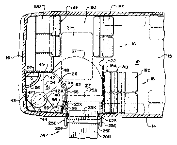
The lavatory compartment is shown in more detail in Figures 2, 3 and 5
and is modified so that it is usable by able bodied passengers and by
wheelchair
passengers.
CA 02162793 2002-09-27
The lavatory compartment therefore comprises a commode 40 covered
by a seat 41. The commode 40 forms part of a molded plastics bench structure
42.
The walls of the compartment are formed from molded plastics defining a rear
wall
43, a first side wall 44 and a second side wall 45. The side wall 44 contains
a
5 window 46 aligned with but smaller than the conventional exterior window of
the
coach body. The window is suitably tinted for privacy. The side wall 44 is
attached
to the wall 14. The rear wall 43 is similarly attached to the rear wall 16 of
the coach
and also contains a window 47 aligned with but smaller than the rear window
(not
shown) of the coach. The side wall 45 extends at right angles to the rear wall
43
10 and the rear wall 16 of the coach body and forms a vertical panel
terminating in a
front edge 48 of the wall 45. The side walls 44 and 45 and the rear wall 43
are
integrally molded with a ceiling 49 from a suitable plastics material such as
fiberglass or vacuum formed acrylic to provide a structural compartment which
can
be mounted inside the coach body. A second component of the compartment is
15 defined by a floor and kick panel element 50 which is again similarly
molded and
includes a floor panel 51 shaped to match the floor defined inside the
compartment
formed by the walls 43, 44 and 45 and including a kick panel which extends
vertically upwardly at one side 52 and at a rear 53 to co-operate with the
walls 43
and 44 respectively.
The commode 40 and bench 42 are formed as a third component of
the compartment. The bench extends across the rear of the compartment in a
first
portion interconnected with the wall 45 and having a frant edge 54 parallel to
the wall
43. From the wall 45, the front edge 54 extends at right angles to the wall 45
to a
CA 02162793 2002-09-27
16
position just forward of the commode 40. The front edge includes a second
portion
55 extending from the position just forward of the commode diagonally to the
front of
the wall 44. The bench extends horizontally from the front edge 54, 55 to the
rear
wall and to the side wall. A center line of symmetry indicated at 40A of the
commode 40 is arranged to substantially intersect with the junction between
the rear
wall 43 and the side wall 44 and to extend therefrom at an angle of the order
of 45°
outwardly from the corner or intersection. This presents the seating position
on the
commode as shown in Figure 3 so that the seated user of the commode faces
outwardly from the carver diagonally in toward the center of the coach.
A sink 56 is molded into the structure of the rear wall 43 and the side
wall 45 at the junction therebetween. A storage cabinet and mirror assembly 57
is
integrally molded with or mounted on the side wall 45 above the sink. A trash
compartment 58 is molded into or attached to the side wall 44.
The side wall 44 includes an edge 59 defining an outermost edge of
the compartment. As shown in Figures 2 and 3, the edge 59 is located at a
position
spaced slightly inwardly from the side wall 14 at the inner edge of the
molding
forming the garbage container 58.
The bench 42 includes a downturned front wall 60 at the edges 54, 55
which co-operates with an upper edge of the rear kick panel section 52, 53.
The area defined underneath the ceiling 49 and between the edges 48
and 59 defines a doorway through which a user can pass to utilize the lavatory
compartment. The doorway is closed by a door construction generally indicated
at
CA 02162793 2002-09-27
7
62. The door construction 62 is formed of two door panels which can be opened
independently.
In the construction shown in Figure 3, the door panels are indicated at
63 and 64 and are arranged as a clam shell arrangement. Thus the door 63 is
pivotally connected along the edge 59 and the door 64 is pivotally connected
to the
edge 48. Thus these doors can move to a fully open position shown in Figure 3
in
which each door pivots outwardly to leave the whole of the doorway open.
However
the door 63 can also be moved to a closed position indicated at 63A and can be
held
in that position while the door 64 can be maved from the open position to a
closed
position indicated at 64A. Thus the door 64 can be operated independently and
the
doorway section defined between an edge 63B of the closed door 63A and the
edge
48 provides a sufficient area for an able bodied passenger to pass into the
compartment behind the seat 18A as best shown in figure 6 for utilizing the
equipment.
In the modified arrangement shown in Figures 2 and 6, the door 62
comprises a first panel 65 which corresponds to the panel 63 and is pivotally
connected at the edge 59. However the door construction further includes a
second
panel 66 which is slidably mounted on the first panel 65 so it slides from a
closed
position abutting the edge 48 to an open position inside the door panel 65.
Again,
however, the door construction 62 operates so that able bodied passengers
simply
operate the door panel 64 or 66 to provide an opening between the edge 48 and
an
edge of the door panel 63, 65 and wheelchair passengers can open the door
fully to
provide a full opening defined by the doorway between the edges 48 and 59.
CA 02162793 2002-09-27
18
A further component of the lavatory compartment comprises a curtain
track 67 which extends from the wall 14 at the forward most position of the
floor area
27 behind the rear most seat 18A in a direction generally across the coach to
the
opposite side of the aisle and then rearwardly to meet a position at the edge
48.
The curtain track is of course mounted at the ceiling or roof the coach so as
to
support a curtain 67A suspended from the curtain track from the ceiling to a
position
at or closely adjacent the floor 15.
Normally the curtain 67A is stored at one end of the track so as to
leave the interior of the coach open for movement of the seats 18A and 18B to
the
deployed position. However when the seats have been moved to the retracted
position and a wheelchair passenger loaded onto the area 27 wishes to use the
lavatory compartment, the wheelchair passenger or an assistant can move the
curtain to the closed position bounding the area 27 and the compartment 26.
This
allows the wheelchair passenger to open the doors 62 to the fully opened
position
shown in Figure 3 while the wheelchair passenger is maintained separate and
private from the remaining passengers by the curtain 67A on the track 67. The
wheelchair passenger can then effect a transfer from the wheelchair to the
commode or can carry out other ablutions as required.
When the wheelchair passenger has completed their ablutions, the
curtain can be opened and the wheelchair removed to a position at one side 14
of
the coach and immediately forwardly of the closed panel of the door thus
leaving the
part of the area 27 adjacent the aisle and forwardly of the door panel 64 open
for
normal movement of passengers along the aisle to the lavatory compartment.
CA 02162793 2002-09-27
79
The positioning of the wheelchair lift immediately forwardly of the
lavatory compartment therefore allows the area 27 to be used both for loading
of the
wheelchair passenger and as an adjunct to the lavatory compartment thus
minimizing the space requirement for the wheelchair passenger while allowing
that
wheelchair passenger full and proper access to the lavatory compartment.
In order to accommodate the wheelchair lift 25, the storage tank for the
commode 40 is modified to a low height, long rectangular tank 40A shown in
Figure
7 which is located underneath the wheelchair lift 25 along the bottom of the
coach
frame adjacent that side wall containing the wheelchair lift. Thus the commode
40
includes a primary storage tank 40B which is connected via a pipe 40C to the
horizontal lower storage tank 40A at the bottom of the coach frame,
Since various modifications can be made in my invention as herein
above described, and many apparently widely different embodiments of same made
within the spirit and scope of the claims without departing from such spirit
and
scope, it is intended that all matter contained in the accompanying
specification shall
be interpreted as illustrative only and not in a limiting sense.