Language selection

Search

Patent 2162873 Summary

Third-party information liability

Some of the information on this Web page has been provided by external sources. The Government of Canada is not responsible for the accuracy, reliability or currency of the information supplied by external sources. Users wishing to rely upon this information should consult directly with the source of the information. Content provided by external sources is not subject to official languages, privacy and accessibility requirements.

Claims and Abstract availability

Any discrepancies in the text and image of the Claims and Abstract are due to differing posting times. Text of the Claims and Abstract are posted:

  • At the time the application is open to public inspection;
  • At the time of issue of the patent (grant).
(12) Patent Application: (11) CA 2162873
(54) English Title: BICYLE RACK
(54) French Title: SUPPORT POUR BICYCLETTE
Status: Deemed Abandoned and Beyond the Period of Reinstatement - Pending Response to Notice of Disregarded Communication
Bibliographic Data
(51) International Patent Classification (IPC):
  • B60R 09/10 (2006.01)
  • B60R 09/06 (2006.01)
  • B62H 03/02 (2006.01)
(72) Inventors :
  • BRYAN, KEN JOHN (Australia)
(73) Owners :
  • KEN JOHN BRYAN
(71) Applicants :
(74) Agent: ROBIC AGENCE PI S.E.C./ROBIC IP AGENCY LP
(74) Associate agent:
(45) Issued:
(86) PCT Filing Date: 1993-07-29
(87) Open to Public Inspection: 1994-12-08
Availability of licence: N/A
Dedicated to the Public: N/A
(25) Language of filing: English

Patent Cooperation Treaty (PCT): Yes
(86) PCT Filing Number: PCT/AU1993/000385
(87) International Publication Number: AU1993000385
(85) National Entry: 1995-11-14

(30) Application Priority Data:
Application No. Country/Territory Date
PL 8987 (Australia) 1993-05-25

Abstracts

English Abstract


A bicycle rack (10) may be supported by a base (40) on
a tow bar of a vehicle. The bicyle rack (10) includes an upright
post (11) having at its upper end a pivotally supported arm (12),
which is adapted by way of grooves (20) to support a number of
bicycles by engagement with the bicycle top tubes. To retain the
bicycles in place, a retaining plate (13) is held against the pivot
arm (12) by wing nuts applied to threaded fasteners (19) and a
padlock which may pass through a hole (22) and a corresponding
hole in the pivot arm (12). A gas strut (18) extends between the
post (11) and the pivot arm (12) to aid in its pivoting. A number
plate support (23) is pivotally attached to the remote end of the
pivot arm (12) and connected to the post (11) by a parallelogram
linkage to maintain the number plate in a generally vertical plane
regardless of the orientation of the pivot arm (12).


French Abstract

Porte-bicyclettes (10) pouvant être supporté par un socle (40) sur une barre de remorquage de véhicule. Le porte-bicyclettes (10) comprend un montant vertical (11) dont l'extrémité supérieure comporte un bras pivotant (12) qui est prévu pour supporter, grâce à des rainures (20), plusieurs bicyclettes qui sont bloquées par le tube horizontal. Pour retenir les bicyclettes en place, une plaque (13) de retenue est maintenue contre le bras de pivotement (12) par des écrous à oreilles vissés sur des fixations filetées (19) et par un cadenas qui peut traverser un trou (22) et un trou correspondant prévu dan le bras de pivotement (12). Un piston à gaz (18) s'étend entre le montant (11) et le bras de pivotement (12) pour faciliter son pivotement. Un support (23) pour plaque d'identification est fixé pivotant à l'extrémité éloignée du bras de pivotement (12) et relié au montant (11) par une articulation en parallélogramme pour maintenir la plaque d'identification dans un plan globalement vertical quelle que soit l'orientation du bras de pivotement.

Claims

Note: Claims are shown in the official language in which they were submitted.

The claims defining the invention are as follows:
1. A bicycle rack comprising:
an upright post to be secured to an object,
an arm pivotably attached to said post and adapted to pivot between a first
orientation essentially parallel with said post, and a second orientation essentially normal
to said post,
means to lock said arm against pivoting in one or more preselected orientations, and
retaining means to lockingly retain at least part of a bicycle to said arm, wherein
said retaining means comprises a plate adapted to be locked to said arm, said plate
comprising a deviation by which a top tube of a bicycle may be secured against said arm.
2. The bicycle rack of claim 1 further comprising a number plate support
pivotally attached to a remote end of said arm.
3. The bicycle rack of claim 2 further comprising means to maintain said number
plate support in a preselected orientation relative to said post throughout pivoting of said
arm.
4. The bicycle rack of claim 3 wherein said maintaining means comprises a
parallelogram link extending from said post to said number plate support.
5. The bicycle rack of claim 1 wherein said arm comprises a groove
corresponding to said deviation.
6. The bicycle rack of claim 1 further comprising a gas cylinder extending
between said post and said arm.
7. The bicycle rack of claim 1 wherein said means to lock comprises at least onelocking boss adapted to pass through corresponding apertures in said post and arm, said
boss being biased by a spring into said apertures, and being retractable from at least one
of said apertures to allow pivoting of said arm relative to said post.
8. The bicycle rack of claim 1 wherein said post is attached to a base, the basebeing attachable to a vehicle.
9. The bicycle rack of claim 8 wherein said post is pivotably lockably mounted to
said base.
10. The bicycle rack of claim 8 wherein the base has a hole therethrough, said
base being supportable by a tow bar and said hole being adapted to receive a tow ball
shaft for secure mounting to said tow bar.
11. In combination, the bicycle rack of claim 1 and a mounting plate adapted to be
secured to a wall, the mounting plate comprising a lug adapted to cooperate so as to
support the post and means to lock the post to the mounting plate.

Description

Note: Descriptions are shown in the official language in which they were submitted.


~CS7AU 9 3 / O ~ ~ 8 5
2 1 6 2 8 7 3 R E~ E I Y E D 2 0 APR t995
Bicycle Rack
Field of the Invention
The following invention relates to bicycle racks. More particularly, though not
exclusively, the invention relates to a bicycle rack which may be affixed to the wall of a
5 garage, or for example to the tow bar of a vehicle, and to securely retain bicycles.
Prior Art
Various means of supporting a bicycle upon a motor vehicle are known. One
method is to simply place the bicycle in the trunk of the vehicle, often requiring the
bicycle to be at least partially ~ m~ntled. Another method is to attach the bicycle by
10 some means to roof racks upon a vehicle's roof or by some other means to the rear of the
vehicle. Such means of attaching bicycles to the roof or rear of the vehicle include
minim~l if any security measures to prevent or deter theft of the bicycle(s).
Object of the Invention
It is the object of the present invention to overcome or substantially ameliorate at
15 least one of the abovementioned disadvantages and/or more generally to provide an
improved bicycle rack.
Disclosure of the Invention
There is disclosed herein a bicycle rack comprising:
an upright post to be secured to an object,
20 an arm pivotably attached to said post and adapted to pivot between a first
orientation essentially parallel with said post, and a second orientation essentially normal
to said post,
means to lock said arm against pivoting in one or more preselected orientations, and
ret~ining means to lockingly retain at least part of a bicycle to said arm, wherein
25 said rc~ g means comprises a plate adapted to be locked to said arm, said plate
colllplisillg a deviation by which a top tube of a bicycle may be secured against said arm.
Preferably, the bicycle rack further comprises a number plate support pivotally
attached to a remote end of said arm.
Preferably, the bicycle rack further comprises means to m~int~in said number plate
30 support in a preselected orientation relative to said post throughout pivoting of said arm.
Preferably, said m~int~ining means comprises a parallelogram link extending fromsaid post to said number plate support.
Preferably, said arm comprises a groove corresponding to said deviation.
Preferably, there is further provided a gas cylinder extending between said post and
35 said arm.
AMENDED SHEET [N:\libll]00183:dss
.__ .. ..

PC~AU 9 3 / O 0 3 8 ~
2162873 RECEIVED 2 0 APR ~995
Preferably, said means to lock comprises at least one locking boss adapted to pass
through corresponding apertures in said post and arm, said boss being biased by a spring
into said apertures, and being retractable from at least one of said apertures to allow
pivoting of said arm relative to said post.
5 Preferably, said post is pivotally attached to a base, said base being adapted to be
supported by a vehicle.
Preferably, said base is pivotally lockably mounted to said post. Altelllalively, said
base comprises a hole thele~ ugh, said base being supportable by a tow bar and said
hole being adapted to receive a tow ball shaft for secure mounting to said tow bar.
10 Also disclosed herein is a combination comprising the above disclosed bicycle rack
and a mounting plate adapted to be secured to a wall, the mounting plate comprises a lug
adapted to cooperate so as to support the post and means to lock the post to the mounting
plate.
Brief Description of the Drawings
15 A preferred form of the present invention will now be described by way of example
with reference to the accompanying drawings, wherein:
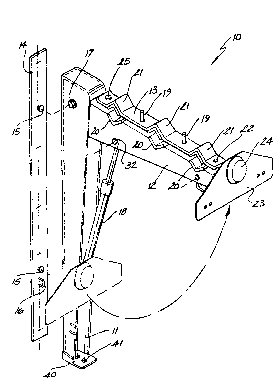
Fig. 1 is a sch~m~tic perspective view of a bicycle rack,
Fig. 2 is a schematic elevational view of the upper portion of the rack of Fig. 1,
Fig. 3 is a schematic elevational view of part of the rack of Fig. 1,
Fig. 4 is a schematic end elevational view of a locking means forming part of the
bicycle rack of Figs. 1, 2 and 3,
Fig. 5 is a schematic plan view of an alternative base forming part of the bicycle
rack of Fig. 1, and
Fig. 6 is a schematic elevational view of the base of Fig. 4 in an open configuration.
Descri~.tion of the Preferred Embodiments
In Fig. 1 of the accon~allyillg drawings there is schem~tic~lly depicted a bicycle
rack 10, typically fabricated from mild steel, all"~ ,ill", or other alloy. Bicycle rack 10
comprises an upright post member 11 comprising a channeled section of C-shape intransverse cross section. At the lower end of post 11, there is provided a base 40 welded
AMENDED SHEET [N:\libll]00183:dss
~ A ~

WO 94127857 2 1 6 2 8 7 3 PCT/AU93/00385
--3--
thereto and comprising a hole 41 through which the threaded shaft of a
tow ball may extend to secure the base 40 to the tow bar of a vehicle.
The threaded shaft of the tow ball may be provided with a transverse
aperture to receive a padlock. However, such a hole need not be provided
or alternatively, any means of securing the tow ball to the tow bar may
be adopted. For example, a nut securing the threaded shaft to the tow
bar may be welded to the threaded shaft and/or tow bar.
At the upper end of post member 11 there is pivotally attached by
way of pivot shaft 17 a pivot arm 12. Extending between a location part
way along pivot arm 12 and a location part way along post 11 is a gas
strut 18. Strut 18 is pivotally attached to arm 12 at pivot point 32.
The arm 12 is provided with one or more grooves 20 upon which the
horizontal upper tube of a bicycle may be placed. Extending upwardly
from the arm 12 is a number of threaded fasteners 18 which pass through a
retaining plate 13. Wing nuts or ordinary nuts may be placed upon
threaded fasteners 19 to firmly secure the retaining plate 13 to the arm
12. At the end of retaining plate 13 proximal to pivot point 17, a lug
25 extends between the retaining plate 13 and arm 12. Lug 25 is long
enough to provide a degree of free movement between plate 13 and arm 12
at that end. At the distal end of retaining plate 13 there is provided a
hole 22 aligned with a corresponding hole in arm 12. As depicted in
Fig. 2, a padlock 33 may pass through the holes to lock the plate 13 onto
arm 12. The retaining plate 13 comprises a number of deviations 21 to
accommodate the horizontal member of respective bicycles. Beneath each
deviation 21 there may be provided padding 26 to prevent scratching of
the bicycle. Similar padding may be provided upon each groove 20 on arm
12.
Also at the distal end of arm 12 is a number plate support member
23. Member 23 is pivotally attached at 45 by way of lug 23 to arm 12.
Welded or otherwise secured to leg 28 is an attachment point 29 to which
a parallelogram link 30 is pivotally attached. Link 30 extends to post
11 where it is also pivotally attached thereto by way of an attachment
point 31 welded or otherwise secured to post 11. The purpose of the
parallelogram link 30 is to maintain the orientation of number plate
support member 23 in a generally vertical orientation throughout the
pivoting movement of arm 23. In the raised position depicted in Fig. 1,
wherein bicycles may be supported by the rack 10, the number plate would
be retained in a position readily visible to anyone behind the vehicle to

WO 94/27857 2 ~ 6 Z 8 7 ~ PCT/AU93/00385
which the rack is attached. When the arm 12 is pivoted down to a closed
configuration, the number plate would remain visible due to its retained
vertical orientation.
As depicted in Figs. 2 and 3, the upper end of post 11 is provided
with a resilient buffer 39 against which arm 12 may abut. A brake light
24 may be provided upon number plate support 23. Light 24 might also
comprise a globe to illuminate the number plate. Electricity is provided
to light 24 by electrlcal cabling 27 shown in Fig. 2.
Referring now to Figs. 3 and 4, a locking device is depicted which
is adapted to retain the arm 12 in a selected pivotal orientation. The
locking device comprises a shaft 36 extending through aligned apertures
in arm 12 and post 11. Fixedly attached to the shaft 36 is a pair of
cross pieces 35, each having attached thereto a locking boss 37. Locking
boss 37 extends through aligned holes in preselected arcuate positions in
arm 12. That is, a pair of holes may be provided in an orientation
providing locking of the arm 12 in a collapsed conf~guration parallel
with post 11 whereas a further set of holes may be provlded in a posltion
providing locking of the arm 12 in the ra~sed position deplcted ln Fig. 1
for example. The bosses 37 would be retained in position through aligned
holes by compression spring 38. To wlthdraw the bosses from the holes, a
handle 34 is provlded.
Also deplcted ln Figs. 1 and 3 is a mounting plate 14 which may be
secured to a garage wall for example. Mounting plate 14 provldes a palr
of supporting lugs 15 which may pass through appropriately shaped
apertures in the back of post 11. Also provided is a padlock eye 16
which may pass through slot 46 ln the back of post 11 and provide a means
by whlch a padlock may be used to secure the post 11 to the wall.
Finally, referring to Fig. 5 and 6, an alternative embodiment base
40 is depicted. This particular embodiment is suitable for application
to station wagons or other vehicles where access may be galned to the
interior of the vehicle by way of a tail gate or the like. In such
instances it would be desirable to pivot the bicycle rack 10 to one side
to gain access to the tail gate. To this end the base 40 is provided
with a hinge 42 at one side thereof and at the other side thereof with a
locking pin arrangement 43. As can be seen, the post 11 may be pivoted
to one side or locked in a vertical orientation by locking pln 43. A
split pin 44 may prevent accidental removal of locking pin 43.

WO 94n7857 2 1 6 2 8 7 3 PCT/AU93/00385
--5--
It should be appreciated that modifications and alterations obvious
to those skilled in the art are not to be considered as beyond the scope
of the present invention. For example, any alternative means of locking
the arm 12 in a desired orientation relative to post 11 may be adopted.
S Furthermore, any means of maintaining the number plate in an essentially
vertical orientation may replace that specifically disclosed.

Representative Drawing
A single figure which represents the drawing illustrating the invention.
Administrative Status

2024-08-01:As part of the Next Generation Patents (NGP) transition, the Canadian Patents Database (CPD) now contains a more detailed Event History, which replicates the Event Log of our new back-office solution.

Please note that "Inactive:" events refers to events no longer in use in our new back-office solution.

For a clearer understanding of the status of the application/patent presented on this page, the site Disclaimer , as well as the definitions for Patent , Event History , Maintenance Fee  and Payment History  should be consulted.

Event History

Description Date
Inactive: IPC from MCD 2006-03-12
Time Limit for Reversal Expired 1999-07-29
Application Not Reinstated by Deadline 1999-07-29
Deemed Abandoned - Failure to Respond to Maintenance Fee Notice 1998-07-29
Application Published (Open to Public Inspection) 1994-12-08

Abandonment History

Abandonment Date Reason Reinstatement Date
1998-07-29

Maintenance Fee

The last payment was received on 1997-07-10

Note : If the full payment has not been received on or before the date indicated, a further fee may be required which may be one of the following

  • the reinstatement fee;
  • the late payment fee; or
  • additional fee to reverse deemed expiry.

Patent fees are adjusted on the 1st of January every year. The amounts above are the current amounts if received by December 31 of the current year.
Please refer to the CIPO Patent Fees web page to see all current fee amounts.

Fee History

Fee Type Anniversary Year Due Date Paid Date
MF (application, 4th anniv.) - small 04 1997-07-29 1997-07-10
Owners on Record

Note: Records showing the ownership history in alphabetical order.

Current Owners on Record
KEN JOHN BRYAN
Past Owners on Record
None
Past Owners that do not appear in the "Owners on Record" listing will appear in other documentation within the application.
Documents

To view selected files, please enter reCAPTCHA code :


To view images, click a link in the Document Description column. To download the documents, select one or more checkboxes in the first column and then click the "Download Selected in PDF format (Zip Archive)" or the "Download Selected as Single PDF" button.

List of published and non-published patent-specific documents on the CPD .

If you have any difficulty accessing content, you can call the Client Service Centre at 1-866-997-1936 or send them an e-mail at CIPO Client Service Centre.


Document
Description 
Date
(yyyy-mm-dd) 
Number of pages   Size of Image (KB) 
Abstract 1994-12-07 1 52
Description 1994-12-07 5 220
Drawings 1994-12-07 5 96
Claims 1994-12-07 1 55
Representative drawing 1998-07-14 1 13
Courtesy - Abandonment Letter (Maintenance Fee) 1998-08-25 1 189
Fees 1997-07-09 1 36
Fees 1996-07-11 1 42
Fees 1995-11-13 1 49
Correspondence 1995-12-06 2 65
International preliminary examination report 1995-11-13 12 358
PCT Correspondence 1996-02-04 1 24
PCT Correspondence 1996-02-13 1 24