Language selection

Search

Patent 2163292 Summary

Third-party information liability

Some of the information on this Web page has been provided by external sources. The Government of Canada is not responsible for the accuracy, reliability or currency of the information supplied by external sources. Users wishing to rely upon this information should consult directly with the source of the information. Content provided by external sources is not subject to official languages, privacy and accessibility requirements.

Claims and Abstract availability

Any discrepancies in the text and image of the Claims and Abstract are due to differing posting times. Text of the Claims and Abstract are posted:

  • At the time the application is open to public inspection;
  • At the time of issue of the patent (grant).
(12) Patent: (11) CA 2163292
(54) English Title: INTERCONNECTED LOCK
(54) French Title: SERRURE COMPOSEE
Status: Expired and beyond the Period of Reversal
Bibliographic Data
(51) International Patent Classification (IPC):
  • E05B 59/00 (2006.01)
  • E05B 53/00 (2006.01)
  • E05B 65/10 (2006.01)
(72) Inventors :
  • ZUCKERMAN, MARTIN (United States of America)
(73) Owners :
  • EMHART INC.
  • NEWFREY LLC
(71) Applicants :
  • EMHART INC. (United States of America)
  • NEWFREY LLC (United States of America)
(74) Agent: NORTON ROSE FULBRIGHT CANADA LLP/S.E.N.C.R.L., S.R.L.
(74) Associate agent:
(45) Issued: 2004-11-09
(22) Filed Date: 1995-11-20
(41) Open to Public Inspection: 1996-06-21
Examination requested: 2002-11-13
Availability of licence: N/A
Dedicated to the Public: N/A
(25) Language of filing: English

Patent Cooperation Treaty (PCT): No

(30) Application Priority Data:
Application No. Country/Territory Date
08/359,967 (United States of America) 1994-12-20

Abstracts

English Abstract


An interconnected lockset comprising an upper
deadbolt assembly including a rotatable spindle, a
turn piece secured to the spindle, the turn piece
rotatable from either of two symmetrical unlocked
orientations to a locked orientation, and a pinion
secured to the turn piece, a lower lever assembly
including a rotatable element, an operator secured to
the rotatable element, and a cam having opposed arms
secured for displacement with the operator, and a
rose for supporting the turn piece and the operator,
a vertically displaceable rack including a pair of
adjacent legs for engagement with the opposed arms,
a vertically extending row of rack teeth, the row of
teeth rack being selectively located so that the
teeth can be either located on one side of the pinion
to rotate the turn piece clockwise from one of the
unlocked orientations to the neutral locked
orientation or located on the other side of the
pinion to rotate the turn piece counterclockwise from
the other unlocked orientation to the neutral locked
orientation.


Claims

Note: Claims are shown in the official language in which they were submitted.

The embodiments of the invention in which an exclusive
property or privilege is claimed axe defined as follows:
1. An interconnected lockset comprising .
an upper deadbolt assembly including
a rotatable spindle,
a turn piece secured to said' spindle,
said turn piece rotatable from either of two
symmetrical unlocked orientations to a locked
orientation, and
a pinion secured to said turn piece,
a lower lever assembly including
a rotatable element,
an operator secured to said rotatable
element, and
a cam having opposed arms secured for
displacement with said operator, and
a rose for supporting said turn piece and
said operator,
a vertically displaceable rack including
a pair of adjacent. legs for
engagement with said opposed arms,
a vertically extending row of rack
teeth,
said row of rack teeth being select-
ively located so that said teeth can be either
located on one side of said pinion to rotate said
turn piece clockwise from one of said unlocked
orientations to said neutral locked orientation or
located on the other side of said pinion to rotate
said turn piece counterclockwise from the other
unlocked orientation to said neutral locked orienta-
tion.
2. An interconnected lockset according to claim 1,
wherein said pinion comprises means for preventing
the removal of said rack except at a selected rack
location.
-6-

3. An interconnected lockset according to claim 2,
further comprising
an elongated slot including an enlarged
cylindrical portion,
hold down screw means extending through
said slot and including a head selectively sized to
pass through said enlarged cylindrical portion of
said elongated slot,
said enlarged slot portion being
selectively located so that said rack can be removed
at said selected rack removal location.
4. An interconnected lockset according to claim 3,
wherein said selected rack location is at a location
between said turn piece locked and turn piece
unlocked positions.
5. An interconnected lockset according to claim 4,
wherein said turn piece is horizontal at said
selected rack locations.
6. An interconnected lockset according to claim 4,
wherein said preventing means comprises a cover
having a flat edge defined to be locatable parallel
to and spaced from said row of teeth when said rack
is at said selected rack location.

Description

Note: Descriptions are shown in the official language in which they were submitted.


SPECIFICATION
INTERCONNECTED LOCK
The present invention relates to locks which
have an upper deadbolt (auxiliary lock) and a lower
lock which are interconnected. The interconnection
is to provide a panic feature, i.e., when the
operator of the interior lower lock is turned the
upper deadbolt will be automatically released.
Interconnected locks have an interior deadbolt
turn piece which should be pointed towards a selected
location (often marked "locked") when the deadbolt is
operated. Since such interconnected locks may be
left or right handed, the deadbolt piece should, with
either installation, rotate to the correct position
pointing to "locked."
The vertical spacing between the upper and
lower locks is also not a single distance and prior
art mechanisms for carrying out the privacy function
are designed for one vertical spacing (U. S. Patent
No. 4,725,085) and are not easily modified for a
different vertical spacing.
It is accordingly an object of the present
invention to provide an interconnected lock with a
privacy function that is very easily modified to
accommodate different vertical spacings.
Other objects and advantages of the present
invention will become apparent from the following
portion of this specification and from the accompany-
ing drawings which illustrate in accordance with the
mandate of the patent statutes a presently preferred
embodiment incorporating the principles of the
invention.
Referring to the drawings:
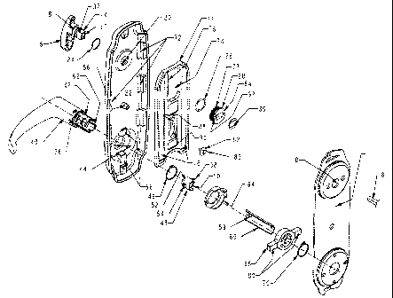
Figure 1 is an oblique exploded view of the
interior portion of an interconnected lockset made in
accordance with the teachings of the present
invention;

- ~163~~2
Figure 2 is a schematic showing of the rack at
the thrown deadbolt position;
Figure 3 is a view similar to that of Figure 2
showing the rack at the bolt retracted position;
Figure 4 is a view similar to that of Figure 2
with the rack at the removal location; and
Figure 5 is a view similar to that of Figure 2
showing the rack positioned for left handed
operation.
The interior half of an interconnected lockset
is shown in Figure 1. The upper lock is a deadbolt
(not shown) which would have a key operated lock on
the exterior of the door which would include a D
shaped spindle 8 which passes through the door,
through a suitable hole 10 in an interior mounting
plate 11 and into a suitable hole 12 in the rectang-
ular end 14 of a turn piece 16. The rectangular end
14 is connected to a cylindrical pilot 18 which
enters an upper hole 20 in the rose 22 with a washer
24 being located between the turn piece 16 and the
rose 22. Located on the rectangular end 14 is a wave
spring 26 and a pinion 28 which are fastened in
position by a retaining clip 30 which is received by
suitable slots 32 in the rectangular end. The bolt
of the deadbolt (not shown) can be thrown or
retracted either by rotating the turn piece approxi-
mately 90° to the illustrated vertical position or by
turning the key in the lock which will also result in
the positioning of the turn piece at the illustrated
vertical locked position.
The lower interior operator could be a simple
lever or knob 40 having an insert 42 which extends
through the lower rose hole 44 and is retained by a
retaining ring 46. A drive locking insert 48 has a
cylindrical hub 50 and a semi cylindrical portion 52.
A first tab 54 projects radially from the semi
cylindrical portion 52 for insertion into one slot 56
-2-

of the lever insert and a second tab 58 extends
radially outwardly from the cylindrical hub, proj ects
through a hole 59 in' a half round 60 and into the
opposing slot 62 of the lever insert 42. The half
round 60 is connected to the lock mechanism and
operates a conventional latch (not shown). The lower
lock can therefore be opened either by turning the
lever or by turning the key in the lock. To maintain
the lever at a horizontal orientation a torque spring
(not shown) which is housed by a torque spring
housing 64 interconnects with tabs 66 on the rose.
The torque spring housing 64 and a cam 68, through
which the half round 60 passes, are secured on the
lever insert 42 by a retaining clip 70.
To retract the deadbolt when the lever is
turned in either direction, a deadbolt retraction
mechanism is provided which includes a rack 71 which
is rectangular in shape and which is slidably
received by opposed pairs of rose guides 72 on the
rose 22. The rack has an opening 74 at its top which
includes vertically extending teeth 76 on one side
which engage with the teeth 77 on the pinion 28. The
bottom of the rack is defined by a pair of opposed
legs 78 which engage the two outwardly projecting
arms 80 of the cam when the rack is at its lowest
position (Figure 2) where the turn piece will be
located at the locked position (the direction of the
turn piece is shown by line 79). Rotation of the
lever 40 in either the clockwise or counterclockwise
direction will result in one of the cam arms 80
engaging one of the rack legs 78 to drive the rack
upwardly to the deadbolt throw orientation (the
interior ends of the legs may be beveled to permit
continued rotation of the lever following the
orientation of the turn piece at the deadbolt release
position).
When the lever is rotated in either direction
-3-

to the bolt throw position (rotated approximately 90°
from horizontal to vertical), the rack will move to
its fully up position (Figure 3). Line 79 again
shows the orientation of the turn piece. At the
deadbolt throw and deadbolt retracted positions
(Figures 2 and 3), removal of the rack is prevented
by the circular head 82 of the hold down screw 83 and
by the pinion flange 84. (The hold down screw 83 is
received by a rose post 86 which is located within a
rack slot which has an elongated top portion 88 and
a circular portion 90 which is larger than the
circular head 82 of the hold down screw).
When the turn piece is turned horizontal, 'he
hold down screw,lies coaxial to a larger hole 90 in
the rack and the pinion is oriented with the flat of
its cover parallel to the rack so that the rack ca.n
be removed. To switch the lever from right hand
operation (the lever is shown 180° from its corre<~t
orientation in Figure 1 for purposes of clarity) 1~0
left hand operation, the turn piece is oriented to be
horizontal (Figure 4). The head of the hold dawn
screw and the circular portion of the rack slot ~~re
now coaxial and the flat edge 92 of the flange 84 is
parallel to and spaced from the teeth 76. The rack
can now be removed and flipped over and the pinion
(and hence the turn piece) can be rotated 180° so
that the rack can be replaced in the rose (Figure 5).
Now, the movement of the rack from the deadbolt
thrown position to the retracted position will ~ tate
the turn piece 110° clockwise (if facing the ;side
of the mechanism) instead of approximately 90°
counterclockwise and to throw the bolt the turn piece
will have to be moved approximately 90° clockwise
(facing inside of door outside of mechanism) instead
of approximately 90° counterclockwise. With this
design the load on the lever throughout its movement
to release the bolt will be constant.
-4-

While the invention has been disclosed with a
simple lever on the interior and a keyed lock which
will automatically lock with key removal, other
combinations are possible. For example, both the
interior and exterior lower operators could be simple
levers or the exterior operator could be keyed.
Other combinations are also possible.
-5-

Representative Drawing
A single figure which represents the drawing illustrating the invention.
Administrative Status

2024-08-01:As part of the Next Generation Patents (NGP) transition, the Canadian Patents Database (CPD) now contains a more detailed Event History, which replicates the Event Log of our new back-office solution.

Please note that "Inactive:" events refers to events no longer in use in our new back-office solution.

For a clearer understanding of the status of the application/patent presented on this page, the site Disclaimer , as well as the definitions for Patent , Event History , Maintenance Fee  and Payment History  should be consulted.

Event History

Description Date
Time Limit for Reversal Expired 2010-11-22
Letter Sent 2009-11-20
Inactive: IPC from MCD 2006-03-12
Grant by Issuance 2004-11-09
Inactive: Cover page published 2004-11-08
Pre-grant 2004-08-18
Inactive: Final fee received 2004-08-18
Notice of Allowance is Issued 2004-07-20
Letter Sent 2004-07-20
Inactive: Approved for allowance (AFA) 2004-07-12
Letter Sent 2003-12-10
Inactive: Multiple transfers 2003-09-18
Letter Sent 2002-12-06
Inactive: Status info is complete as of Log entry date 2002-12-06
Inactive: Application prosecuted on TS as of Log entry date 2002-12-06
Amendment Received - Voluntary Amendment 2002-11-13
Request for Examination Requirements Determined Compliant 2002-11-13
All Requirements for Examination Determined Compliant 2002-11-13
Application Published (Open to Public Inspection) 1996-06-21

Abandonment History

There is no abandonment history.

Maintenance Fee

The last payment was received on 2003-11-04

Note : If the full payment has not been received on or before the date indicated, a further fee may be required which may be one of the following

  • the reinstatement fee;
  • the late payment fee; or
  • additional fee to reverse deemed expiry.

Please refer to the CIPO Patent Fees web page to see all current fee amounts.

Owners on Record

Note: Records showing the ownership history in alphabetical order.

Current Owners on Record
EMHART INC.
NEWFREY LLC
Past Owners on Record
MARTIN ZUCKERMAN
Past Owners that do not appear in the "Owners on Record" listing will appear in other documentation within the application.
Documents

To view selected files, please enter reCAPTCHA code :


To view images, click a link in the Document Description column. To download the documents, select one or more checkboxes in the first column and then click the "Download Selected in PDF format (Zip Archive)" or the "Download Selected as Single PDF" button.

List of published and non-published patent-specific documents on the CPD .

If you have any difficulty accessing content, you can call the Client Service Centre at 1-866-997-1936 or send them an e-mail at CIPO Client Service Centre.


Document
Description 
Date
(yyyy-mm-dd) 
Number of pages   Size of Image (KB) 
Representative drawing 1999-08-09 1 29
Cover Page 1995-11-20 1 14
Abstract 1995-11-20 1 28
Description 1995-11-20 5 191
Claims 1995-11-20 2 62
Drawings 1995-11-20 5 103
Representative drawing 2004-10-06 1 20
Cover Page 2004-10-06 2 56
Reminder of maintenance fee due 1997-07-22 1 111
Reminder - Request for Examination 2002-07-23 1 127
Acknowledgement of Request for Examination 2002-12-06 1 174
Commissioner's Notice - Application Found Allowable 2004-07-20 1 162
Maintenance Fee Notice 2010-01-04 1 170
Correspondence 2004-08-18 1 28