Language selection

Search

Patent 2163538 Summary

Third-party information liability

Some of the information on this Web page has been provided by external sources. The Government of Canada is not responsible for the accuracy, reliability or currency of the information supplied by external sources. Users wishing to rely upon this information should consult directly with the source of the information. Content provided by external sources is not subject to official languages, privacy and accessibility requirements.

Claims and Abstract availability

Any discrepancies in the text and image of the Claims and Abstract are due to differing posting times. Text of the Claims and Abstract are posted:

  • At the time the application is open to public inspection;
  • At the time of issue of the patent (grant).
(12) Patent Application: (11) CA 2163538
(54) English Title: METHOD AND APPARATUS FOR USE IN THE PRESS OR DRYER SECTION OF A PAPER MACHINE OR SIMILAR EQUIPMENT
(54) French Title: PROCEDE ET DISPOSITIF POUR UTILISATION DANS LES SECTIONS PRESSE OU SECHERIE D'UNE MACHINE A PAPIER OU AUTRE EQUIPEMENT ASSIMILE
Status: Deemed Abandoned and Beyond the Period of Reinstatement - Pending Response to Notice of Disregarded Communication
Bibliographic Data
(51) International Patent Classification (IPC):
  • D21F 05/04 (2006.01)
  • D21F 03/02 (2006.01)
(72) Inventors :
  • KOSKINEN, PEKKA (Finland)
  • HAVERINEN, TIMO (Finland)
(73) Owners :
  • EV GROUP OY
(71) Applicants :
  • EV GROUP OY (Finland)
(74) Agent: ROBIC AGENCE PI S.E.C./ROBIC IP AGENCY LP
(74) Associate agent:
(45) Issued:
(86) PCT Filing Date: 1994-04-27
(87) Open to Public Inspection: 1994-12-08
Availability of licence: N/A
Dedicated to the Public: N/A
(25) Language of filing: English

Patent Cooperation Treaty (PCT): Yes
(86) PCT Filing Number: PCT/FI1994/000164
(87) International Publication Number: FI1994000164
(85) National Entry: 1995-11-22

(30) Application Priority Data:
Application No. Country/Territory Date
932434 (Finland) 1993-05-27

Abstracts

English Abstract


A method for cleaning one or more orifice slots
(2, 3) of a blow box (1) or similar object particularly
in the press or dryer section of a paper machine or
similar equipment. The orifice slot (2, 3) is subjected
to treatment from inside the blow box by means of
one or more mechanical cleaning elements (4) and/or
a cleaning jet (8, 9, 23). The invention also concerns
an apparatus suited for implementing said method,


French Abstract

Procédé de nettoyage d'une ou plusieurs fentes d'orifices (2, 3) d'un caisson de soufflage (1) ou l'équivalent, en particulier dans la presse ou la sécherie d'une machine à papier ou d'un équipement similaire. Les fentes d'orifices (2, 3) sont soumises à un traitement de l'intérieur du caisson de soufflage au moyen d'un ou plusieurs éléments de nettoyage mécaniques (4) et/ou d'une tuyère nettoyante (8, 9, 23). L'invention porte également sur un appareil permettant d'appliquer ledit procédé.

Claims

Note: Claims are shown in the official language in which they were submitted.

Claims
1. A method for cleaning one or more orifice slots
(2, 3) of a blow box (1) or similar object particularly
in the press or dryer section of a paper machine or
similar equipment, c h a r a c t e r i z e d in that
the orifice slot (2, 3) is subjected to treatment from
inside the blow box by means of one or more mechanical
cleaning elements (4) and/or a cleaning jet (8, 9, 23).
2. A method as defined in claim 1, c h a r a c t e r -
i z e d in that the said cleaning jet (8, 9, 23) is
operated using a liquid and/or gaseous medium or mixture
thereof ejected at an elevated pressure.
3. A method as defined in claim 1 or 2, c h a r a c -
t e r i z e d in that the said mechanical cleaning
element (4) and/or said cleaning jet (8, 9, 23) is
movable, advantageously in the longitudinal direction of
the orifice slot (2, 3).
4. A method as defined in any foregoing claim 1 - 3,
c h a r a c t e r i z e d in that the moving force for
said cleaning jet (8, 9, 23) is attained by tilting the
jet or at least a part of the jet.
5. An apparatus capable of implementing the method
defined in claim 1, suited for cleaning the orifice slots
(2, 3) of a blow box (1) in a paper machine or similar
equipment, c h a r a c t e r i z e d in that means (4,
8, 9, 23) are adapted to the interior of the blow box (1)
for cleaning the orifice slot (2, 3).
6. An apparatus as defined in claim 5, c h a r a c -
t e r i z e d in that the said cleaning means (4) are
comprised of one or more mechanical cleaning elements (4)
adapted movable, preferably in the longitudinal direction

of the orifice slot (2), in the orifice slot (2) of the
blow box (1) or close to it.
7. An apparatus as defined in claim 5, c h a r a c -
t e r i z e d in that the said cleaning means (8, 9, 23)
are comprised of one or more cleaning nozzle elements (8,
9, 23) advantageously directed toward the orifice slot
(2, 3) and into which cleaning nozzle elements (8, 9, 23)
a liquid and/or gaseous cleaning medium or mixture
thereof can be routed via piping (10, 11, 12, 13, 20) or
similar arrangement.
8. An apparatus as defined in any foregoing claim 5 - 7,
c h a r a c t e r i z e d in that the said cleaning
nozzle element (8, 9, 23) is arranged movable inside the
blow box (1).
9. An apparatus as defined in any foregoing claim 5 - 8,
c h a r a c t e r i z e d in that the said cleaning
nozzle element (23), or alternatively, one or more of the
jet orifices of the cleaning nozzle element are aligned
at an angle .alpha. so that the jet exiting the nozzle (23)
imparts a reaction force capable of moving the nozzle
element (19, 23).
10. An apparatus as defined in any foregoing claim 5 - 9,
c h a r a c t e r i z e d in that the said cleaning
nozzle element (23) is connected to a high-pressure
washer or similar equipment advantageously capable of
generating a pressure of approx. 80-120 bar.

Description

Note: Descriptions are shown in the official language in which they were submitted.


~ WO94/2~1 PCT/F~4/00164
~163538
M~thod and appar~tus for use in the press or dryer
s~ction of a paper machine or similar eguipment
The invention relates to a method intended for applica-
tions in a paper machine or similar equipment, particu-
larly for cleaning orifice slots or similar objects in
the blow boxes or similar units of the press or dryer
sections.
Further, the invention concerns an apparatus implementing
said method according to the invention for cleaning the
orifice slots of a blow box.
Paper and board machines conventionally use blow boxes
within the single-wire region for supporting the web.
Such apparatuses are described in FI laid-open publica-
tion 69332 and FI laid-open publication 65460.
Air to the blow boxes is generally taken as recycle air
from inside the hood of a paper machine or similar equip-
ment. The recycle air is contaminated by, e.g., dust
whose landing into the blow box clogs the orifice slots
of the blow box at least partially, thereby worsening the
efficiency of the box. Impairment of the box function
causes web instability such as flutter, whereby the
frequency of web breaks and other malfunctions increases.
Obviously, such problems result in decrease of production
output and profitability at the paper machine or similar
equipment.
It is an object of the present invention to achieve a
method capable of overcoming the problems associated with
the clogging of the blow boxes. A further object is to
attain apparatus implementing said method, suited for
rapid and easy cleaning of the orifice slots. The inven-
tion is based on cleaning the slots of the blow box from

WO94128~1 PCT~94/00l64
2 1635 38 2
inside the blow box using means adapted to the inside of
the box.
More specifically, the invention is characterized by what
is stated in the characterizing part of claim l.
Furthermore, the apparatus implementing the method is
characterized by what is stated in the characterizing
part of claim 5.
The invention offers several important benefits. The
orifice slot of the blow box can be cleaned rapidly and
easily. Thus, the clogging of the slots is avoided,
whereby the web can be run stably and with less risk of
web breaks. By arranging the cleaning means movable, a
simple and effective system for cleaning the orifice slot
is attained. Implementing the cleaning means by way of a
cleaning jet nozzle from which the cleaning solution is
ejected at elevated pressure, the cleaning efficiency can
be further improved. A tilted orientation of the cleaning
jet nozzle or the orifice holes of the nozzle provides an
advantageous and fail-safe transfer arrangement of the
nozzle head.
In the following the invention is examined in greater
detail by way of advantageous exemplifying embodiments
with reference to the annexed drawings in which
Fig. l shows a side view of a blow box in which the
method according to the invention is implemented
for cleaning an orifice slot by means of a
m~ch~nical cleaning element,
Fig. 2 shows the blow box illustrated in Fig. l with the
bottom plate removed,

~ WO94/28~1 PCT/F~4/00164
21~353~
Fig. 3 shows a de~ail of the blow box illustrated in
Fig. 1,
Fig. 4 shows a side view of a blow box in which the
method according to the invention is implemented
by way of fixed cleaning jets for cleaning an
orifice jet,
Fig. 5 shows the blow box illustrated in Fig. 4
with the bottom plate removed,
Fig. 6 shows an alternative embodiment of the arrange-
ment illustrated in Fig. 4,
Fig. 7 shows a blow box in which the method
according to the invention is implemented
for cleaning an orifice slot by way of a
moving cleaning jet,
Fig. 8 shows the blow box illustrated in Fig. 7 with the
bottom plate removed, and
Fig. g shows a detail of the blow box illustrated in
Fig. 7.
With reference to Fig. 1, a blow box 1 employed in the
press or dryer section of a paper machine or similar
equipment is shown in partially sectional side view. The
blow box 1 has two orifice slots 2, 3, which are advanta-
geously aligned perpendicular to the web machine direc-
tion extending advantageously over the entire width of
the web, and a manifold for routing the blowing air into
the slots. The orifice slot 2 is provided with a meGh~ni-
cal cleaning element 4 which is moved over the longitudi-
nal direction of the orifice slot 2 by means of a drivemachinery 5, 6, 7. The drive machinery is comprised of
one or more, advantageously three, drive wheels, for

WO94/28~1 PCT/F~4/00164
` ~16~38 4
instance chain sprockets 6, and a drive chain 5 or
similar means routed through the drive wheel set. The
cleaning element 4 is arranged movable along with the
drive chain 5 or equivalent means as shown in Fig. 3. A
drive actuator such as an electric motor 7 is arranged to
rotate the drive wheels 6 via, e.g., a shaft. The motor
can also be of a reversible type, thus permitting a
reciprocating movement of the cleaning element in the
orifice slot. The cleaning element 4 is advantageously a
0 peg with a diameter of 1-5 mm for instance, advantageous-
ly 2 mm. The drive machinery can be interlocked with the
automatic web break control system of the paper machine
or equivalent equipment, whereby the cleaning sequence
can be run automatically during a web break.
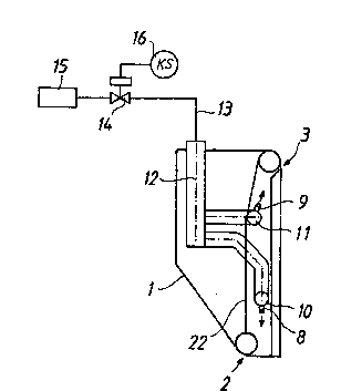
Fig. 4 shows a blow box 1 arranged to have several fixed
cleaning jet nozzles 8, 9 for cleaning orifice slots
2, 3. The intermediate chamber 22 of the blow box 1 is
adapted to incorporate one or more pipes 10, 11 into
which a liquid and/or gaseous cl~n;n~ medium or a mix-
ture thereof is routed. The cleaning jet nozzles 8, 9 are
mounted to the pipes 10, 11 so that the orifice holes of
the nozzle are advantageously aligned toward the orifice
slots 2, 3 of the blow box. The pipes 10, 11 have a
length advantageously ext~ing over essentially the
entire length of the blow box. The cleaning jet nozzles
8, 7 are mounted to the pipes 10, 11 at a spacing of
approx. 4-10 pcs./meter. The nozzles 8, 9 are arranged
into the blow box 1 in a ~nner permitting the cl~n;~g
medium jets exiting from the nozzles to cover essentially
the entire area of the orifice slot 2, 3. In an advanta-
geous embodiment an intermediate pipe 17 is adapted
between the pipe 10 and the nozzle 8, whereby the nozzles
8 can be brought closer to the orifice slot 2. Then, the
cleaning medium jet is aligned directly toward the
orifice slot 2.

WO94/28~11 ~1~ 3 5 3 8 P~T/F~4/00164
When necessary, the pipes 10, 11 can be connected in the
interior of the blow box to the pipe 12 which is further
connected via a pipe 13 to the piping network running
outside the blow box 1. The inlet pipe to the cleaning
system is advantageously provided with a filter element
15 for removal of impurities from the cleaning jet. The
filter element 15 is advantageously a microporous filter
with a pore size of 200-500 ~m typical. The inlet pipe 13
is also equipped with a stop/control element 14, which
with the help of a control means such as a timer control-
ler 16 directs the cleaning medium into one blow box at a
time. The stop/control element 14 is advantageously a
solenoid valve. The cleaning medium is pumped with the
help of a pump (not shown in the diagrams) into the plant
piping network.
With reference to Figs. 7, 8 and 9, another preferred em-
bodiment is shown in which the intermediate chamber 22 of
th~e blow box 1 is provided with a control element 18 such
as a guide rail having a width advantageously extending
essentially over the entire blow box. The blow box 1,
ad~antageously its end, is e~uipped with a sealable
opening through which a cleaning nozzle 23 can be mounted
to the interior of the blow box 1. The cleaning nozzle 23
is adapted onto a counter piece 19 such as a sliding
carriage or eguivalent, compatible with the guide element
18p whereby the counter piece 19 and the guide rail 18
are designed mutually compatible in a manner that permits
moving the cleaning nozzle head 23 along the guide rail
over the blow box from end to end. The cleaning nozzle
23, or alternatively, one or more of the nozzle orifices
of the nozzle head are aligned at an angle ~, thereby
causing the cleaning medium jet exiting the nozzle 23 to
impart a reaction force which pushes the cleaning nozzle
mounted on the control element along the guide rail 18.
Thus, the orifice slot of the blow box can be entirely
cleaned using only a single nozzle. The cleaning nozzle

WO94/28~1 PCT/F~4/00164 ~
~-3~3~
23 is advantageously connected to a pump 21,
advantageously a high-pressure cleaner or similar by way
of a flexible hose 20 or equivalent means. The high-
pressure cleaner 21 is advantageously operated at approx.
80-120 bar pressure. The high-pressure cleaner 21 is
advantageously connected in a conventional manner to
water piping. The benefit of this embodiment is therein
that a single cleaning apparatus can be used in a number
of blow boxes. The blow boxes only have to be designed
0 with an opening for introducing the cleaning nozzle 23
into the blow box and the nozzle element must be provided
with a control element 18.
For those versed in the art it is obvious that the
invention is not limited to the exemplifying embodiments
described above, but rather, can be varied within the
scope of the ~nne~e~ claims. Thus, the blow box can be
provided with multiple cl~n; ng elements operating in
different principles.

Representative Drawing
A single figure which represents the drawing illustrating the invention.
Administrative Status

2024-08-01:As part of the Next Generation Patents (NGP) transition, the Canadian Patents Database (CPD) now contains a more detailed Event History, which replicates the Event Log of our new back-office solution.

Please note that "Inactive:" events refers to events no longer in use in our new back-office solution.

For a clearer understanding of the status of the application/patent presented on this page, the site Disclaimer , as well as the definitions for Patent , Event History , Maintenance Fee  and Payment History  should be consulted.

Event History

Description Date
Inactive: IPC from MCD 2006-03-12
Deemed Abandoned - Failure to Respond to Maintenance Fee Notice 2002-04-29
Inactive: Dead - RFE never made 2002-04-29
Application Not Reinstated by Deadline 2002-04-29
Inactive: Abandon-RFE+Late fee unpaid-Correspondence sent 2001-04-27
Application Published (Open to Public Inspection) 1994-12-08

Abandonment History

Abandonment Date Reason Reinstatement Date
2002-04-29

Maintenance Fee

The last payment was received on 2001-03-14

Note : If the full payment has not been received on or before the date indicated, a further fee may be required which may be one of the following

  • the reinstatement fee;
  • the late payment fee; or
  • additional fee to reverse deemed expiry.

Patent fees are adjusted on the 1st of January every year. The amounts above are the current amounts if received by December 31 of the current year.
Please refer to the CIPO Patent Fees web page to see all current fee amounts.

Fee History

Fee Type Anniversary Year Due Date Paid Date
MF (application, 4th anniv.) - standard 04 1998-04-27 1998-03-25
MF (application, 5th anniv.) - standard 05 1999-04-27 1999-03-10
MF (application, 6th anniv.) - standard 06 2000-04-27 2000-03-20
MF (application, 7th anniv.) - standard 07 2001-04-27 2001-03-14
Owners on Record

Note: Records showing the ownership history in alphabetical order.

Current Owners on Record
EV GROUP OY
Past Owners on Record
PEKKA KOSKINEN
TIMO HAVERINEN
Past Owners that do not appear in the "Owners on Record" listing will appear in other documentation within the application.
Documents

To view selected files, please enter reCAPTCHA code :


To view images, click a link in the Document Description column (Temporarily unavailable). To download the documents, select one or more checkboxes in the first column and then click the "Download Selected in PDF format (Zip Archive)" or the "Download Selected as Single PDF" button.

List of published and non-published patent-specific documents on the CPD .

If you have any difficulty accessing content, you can call the Client Service Centre at 1-866-997-1936 or send them an e-mail at CIPO Client Service Centre.

({010=All Documents, 020=As Filed, 030=As Open to Public Inspection, 040=At Issuance, 050=Examination, 060=Incoming Correspondence, 070=Miscellaneous, 080=Outgoing Correspondence, 090=Payment})


Document
Description 
Date
(yyyy-mm-dd) 
Number of pages   Size of Image (KB) 
Abstract 1994-12-07 1 45
Description 1994-12-07 6 250
Drawings 1994-12-07 3 54
Claims 1994-12-07 2 73
Representative drawing 1998-07-15 1 5
Reminder - Request for Examination 2000-12-27 1 119
Courtesy - Abandonment Letter (Request for Examination) 2001-06-10 1 171
Courtesy - Abandonment Letter (Maintenance Fee) 2002-05-26 1 183
Fees 1999-03-09 1 35
Fees 2000-03-19 1 29
Fees 2001-03-13 1 32
Fees 1998-03-24 1 40
Fees 1997-03-19 1 43
Fees 1996-03-13 1 46
Courtesy - Office Letter 1996-01-03 1 18
International preliminary examination report 1995-11-21 21 645