Note: Descriptions are shown in the official language in which they were submitted.
WO 94/28842 PCT/US94/05788
~~.63733
ABSORBENT ARTICLES PROVIDING SUSTAINED DYNAMIC FIT
FIELD OF THE INVENTION
The present invention relates to absorbent articles such as
diapers, incontinent briefs, training pants, diaper holders and
liners, sanitary hygiene garments, and the like, and more
particularly, to absorbent articles providing sustained dynamic
fit about the wearer.
BACKGROUND OF THE INVENTION
Infants and other incontinent individuals wear absorbent
articles such as diapers to absorb and contain urine and other
body exudates. Absorbent articles function both to contain the
discharged materials and to isolate these materials from the body
of the wearer and from the wearer's garments and bed clothing.
Disposable absorbent articles having many different basic designs
are known in the art. For example, U.S. Patent Re. 26,152,
entitled "Disposable Diaper" issued to Duncan and Baker on January
31, 1967, describes a disposable diaper which has achieved wide
acceptance and commercial success. U.S. Patent 3,860,003,
entitled "Contractable Side Portions .For Disposable Diaper",
issued to Buell on January 14, 1975, describes an elastic leg cuff
disposable diaper which has achieved wide acceptance and
commercial success.
su~sTrrur~ ~~~ ~~~~E 2s~
PCTIUS94105788
WU 9428842 ~6'~~
2
However, absorbent articles have a tendency to sag or gap
away from and to slide/slip down on the body of the wearer during
use. This sagging/gapping and sliding/slipping is caused by the
relative motions of the wearer as the wearer breathes, moves and
changes position, by the downward forces generated when the
absorbent article is loaded with body exudates, and by the
deformation of the materials of the absorbent article itself when
subjected to such wearer's motions. This sagging/gapping and
sliding/slipping of the absorbent article can lead to premature
leakage and poor fit of the absorbent article about the wearer.
Conventional disposable diapers are typically designed to fit
high on the abdomen of the wearer and down on the thighs such that
the diaper fits in the zones of the wearer that are subject to
dynamic motion (and thus dynamic forces) during use. These
dynamic motions and forces, especially by the abdomen bulging and
contracting, tend to deform the materials making up the diaper arid
tend to push the diaper away from the body. Thus, the diaper
tends to sag/gap away from the body. The closure system of the
diaper is also typically designed to form a defined dimension of
the waist and leg openings and a line of tension (imparts a
tensile force along a line) about the wearer to secure the diaper
on the wearer. However, this defined waist dimension created by
the closure system cannot accommodate the changes in body
dimension caused by wearer movement such that the diaper tends to
slide/slip down on the wearer when the dimension of the abdomen of
the wearer becomes smaller than the defined dimension formed by
the closure. Further, when the abdominal dimension becomes larger
than the defined dimension formed by the closure system, the body
tends to push the diaper to a different position on the wearer
(typically to a smaller dimension area which is lower than the
point of initial fit) or the diaper tends to be so tight on the
abdomen that the diaper can mark the skin or be uncomfortable to
wear. Further) the absorbent core and other stiff nonelastic
members of the diaper typically fit in the zones of the abdomen or
1 egs that undergo such dynami c forces that the absorbent core i s
pushed downward or inward by the dynamic forces resulting in
further gapping/sliding of the product on the wearer.
su~r~rurE sH~r csu~E 2~
2~6~~3
8
In order to more snugly fit absorbent articles about the wearer, certain
commercially available absorbent articles have been provided with elastic
features about the waist, hips, or legs. An example of a disposable diaper
with an elastic waist feature which has achieved wide acceptance and
commercial success is disclosed in U.S. Patent 4,515,595 issued to Kievit and
Osterhage on May 7, 1985. An example of a disposable diaper with an elastic
leg cuff is disclosed in the previously mentioned U.S. Patent 3,860,003. An
example of a disposable diaper with elastic side panels to fit over the hips
is
disclosed in U.S. Patent 4,857,067 issued to Wood, et al. on August 15, 1989.
The elastic features are designed to expand and contract with the wearer's
motions and to maintain the fit of the absorbent article about the wearer
during use (i.e., provide sustained dynamic fit).
However, it has been found that absorbent articles having elastic
features also have a tendency to sag/gap and slide/slip during use.
Thus, it would be advantageous to provide an absorbent article that
provides better fit, reduced leakage, and wearer comfort. It would further be
advantageous to provide an absorbent article which has reduced sagging and
gapping as well as reduced overall sliding/ slipping of the absorbent article
and/or the absorbent core on the wearer during use.
Therefore, it is an object of an aspect of the present invention to
provide an absorbent article having sustained dynamic fit about the wearer
during use by reducing the sagging/gapping and sliding/slipping of the
absorbent article on the wearer.
It is an object of an aspect of the present invention to provide an
absorbent article providing increased comfort for the wearer by providing
freedom of motion for the wearer and minimizing the effects of forces caused
by wearer's movements on product stability.
It is an object of an aspect of the present invention to provide an
absorbent article shaped to fit within the low motion zone of the wearer
and/or to provide expansion of the absorbent article at those portions not
fitting within the low motion zone.
I
263738
It is an object of an aspect of the present invention to anchor the
absorbent article about the perimeter of the low motion zone of the wearer to
achieve sustained dynamic fit.
It is an object of an aspect of the present invention to provide an
absorbent article having an absorbent core shaped to fit in the low motion
zone of the wearer so that the absorbent article has sustained dynamic fit
during use.
It is an object of an aspect of the present invention to provide a closure
system and containment assembly (chassis) design that anchor the absorbent
core in the low motion zone of the wearer to enhance the sustained dynamic
fit.
It is an object of an aspect of the present invention to provide a
containment assembly (chassis) design, closure system and an absorbent core
shape cooperating to reduce sagging and gapping as well as overall
sliding/slipping of the absorbent article during use.
These and other objects of the present invention will be more readily
apparent when considered in reference to the following description and when
taken in conjunction with the accompanying drawings.
SUMMARY OF THE INVENTION
The present invention provides absorbent articles such as diapers,
incontinent briefs, training pants, diaper holders and liners, feminine
hygiene
garments, and the like, designed to provide sustained dynamic fit about the
wearer during use as well as to improve the containment of body exudates
and wearer comfort/ mobility. Such an absorbent article has a containment
assembly (chassis) comprising an outer covering layer typically comprising a
liquid pervious topsheet and a liquid impervious backsheet, and an absorbent
core associated with the outer covering layer. The absorbent core is
preferably designed to fit within the low motion zone of the wearer (an
anatomically low motion zone-fitting absorbent core) so that dynamic forces
imparted by movements of the wearer on the absorbent core are minimized.
The absorbent article is also provided with a closure
r'~';
WO 94/28842 PCT/US94105788
system for anchoring the absorbent article on the wearer to
sustain the dynamic fit of the absorbent article about the wearer
throughout wearing. The closure system is designed so that a
primary line of tension, fitting at an angle to the body, is
formed to secure the absorbent article on a wearer in a manner
that does not contribute to sagging or sliding of the diaper. The
absorbent article preferably further comprises elastic features
for fitting about the extremities of the wearer including elastic
waist features, elastic leg cuffs, and elastic side panels that
allow freedom of movement for the wearer as well as maintenance of
forces about the body to sustain the fit of the absorbent article.
In a preferred embodiment of the present invention, the
absorbent core is designed to fit within the low motion zone of
the wearer (i.e., an anatomically low motion zone-fitting
absorbent core). By designing the shape of the absorbent core to
fi t i n the 1 ow moti on zone of the wearer, the absorbent core is
not likely to sag/gap or slip/slide during use since the absorbent
core is positioned in the area of the wearer having little or no
dynamic motions or forces tending to cause it to gap or slip. The
absorbent core is provided with a front waist edge preferably
having an arcuate concave shape to fit below or at the abdominal
crease of the wearer. It is preferred that the curve of the front
waist edge approximate the curve of the abdominal crease of the
wearer such that the absorbent core will naturally fit into the
low motion zone to maximize the comfort for the wearer. The
absorbent core i.s also provided with arcuate concave side edges
designed to fit in the.leg creases of the wearer and to define a
narrow crotch width which:.fits between the legs of the wearer.
These leg cutouts are positioned farther forward in the absorbent
core than the later.~l.centerline so that the front portion of the
absorbent core is s,iio'rter 'in length to fit below the abdominal
crease and to allow,the~. absorbent core to fit higher over the
buttocks and into the ~l~umbar curve of the back. Preferably, the
absorbent core is long enou~ghyln,the back to fit upwardly over the
buttocks of the wearer into the~1''ut~be~r~curve of the back to anchor
the back and to provide less gaping of the absorbent core in the
back to further enhance BM containment.
SUBSTIiU(E SHEET (RULE 26)
~:2~63738
The absorbent article is also preferably provided with a closure system
for anchoring the absorbent article on the wearer. Preferably, the closure
system provides a primary line of tension around the wearer that fits
predominantly within the low motion zone to enhance the dynamic fit and to
anchor the absorbent core in place so that it will not slip/ slide during use.
The primary line of tension established by the closure system is disposed at
an angle on the wearer. In a preferred embodiment of the present invention,
the closure system is provided with angled tapes, more preferably tapes of a
specified design, to allow the wearer to easily form the "angled" primary line
of tension about the wearer. The closure system is also provided with a
landing member designed to enhance the opportunity for the user to establish
this primary line of tension equally each time the closure system is used.
In an especially preferred embodiment of the present invention, the
absorbent article additionally comprises elastic features positioned outside
of
the absorbent core to enhance the dynamic fit of the absorbent article about
the wearer in those zones that undergo dynamic changes caused by the
wearer s movements. In one embodiment, any zone outside of the absorbent
core is elasticized to provide this type of fit. In an especially preferred
embodiment, the absorbent article is provided with elastic waist features,
elastic leg cuffs, and elastic side panels that provide elastic extensibility
to
provide greater freedom of movement for the wearer and a more comfortable
and contouring fit by initially conformably fitting the diaper to the wearer
and by sustaining this fit during use.
Other aspects of this invention are as follows:
An absorbent article for fitting about a wearer to contain body
exudates, the wearer having a low motion zone, the absorbent article
comprising:
a contairunent assembly having a front waist region, a back waist
region opposed to said front waist region, a front end edge, a back end edge,
longitudinal edges, a longitudinal axis, a longitudinal direction defined as
the
direction parallel to said longitudinal axis, a lateral axis, a lateral
direction
defined as the direction parallel to said lateral axis, said containment
assembly comprising:
an outer covering layer; and
an anatomically low motion zone-fitting absorbent core
associated with said outer covering layer, said absorbent core having a
6a 2 ~ 6 3 7 3 8
longitudinal centerline, side edges, a from wGist edge having an
abdominal point oriented on said longihzdinul centerline, and a back
waist edge, each said side edge having a leg segment and a buttocks
segment, each said leg segment having a substantially concave arcuate
shape so as to provide a narrowed crotch portion to fit between the
legs of the wearer which defines a crotch point, said absorbent core
being positioned within said containment assembly such that the ratio
of the longitudinal distance from said crotch points to said back end
edge of said containment assembly to the longitudinal distance from
said abdominal point to said crotch points is at least about 1.5:1; and
closure means for anchoring the absorbent article on the wearer by
forming a primary line of tension disposed at an angle of greater than about
5° from the lateral direction about the perimeter of the low motion
zone of the
wearer to sustain the fit of the absorbent article throughout wearing, said
closure means being joined to said containment assembly.
A unitary disposable absorbent article for fitting about a wearer to
contain body exudates, the wearer having a low motion zone, the absorbent
article comprising:
a containment assembly having a front waist region, a back waist
region opposed to said front waist region, a front end edge, a back end edge,
longitudinal edges, a longitudinal axis, a longitudinal direction defined as
the
direction parallel to said longitudinal axis, a lateral axis, and a lateral
direction defined as the direction parallel to said lateral axis, said
containment assembly comprising:
an outer covering layer;
an anatomically low motion zone-fitting absorbent core joined
with said outer covering layer, said absorbent core having a
longitudinal centerline, side edges, a front waist edge having an
abdominal point oriented on said longitudinal centerline, and a back
waist edge, each said side edge having a leg segment and a buttocks
segment, each said leg segment having a substantially concave arcuate
shape so as to provide a narrowed crotch portion to fit between the
legs of the wearer which defines a crotch point, said absorbent core
being positioned within said contairunent assembly such that the ratio
of the longitudinal distance from said crotch points to said back end
edge of said contairunent assembly to the longitudinal distance from
. .,
',~~.:~ ..:v
6b _ 2163738
said abdominal point to said crotch points is at least about 1.5:1;
a back elasticized waistband positioned in said back waist
region, said back elasticized waistband providing elastic extensibility
having a vector component in the lateral direction; and
elastic side panels positioned in said back waist region, said
elastic side panels being elastically extensible in a direction having a
vector component in the longitudinal direction; and
closure means for anchoring the absorbent article on the wearer by
forming a primary line of tension disposed at an angle of between about
5°
and about 30° from the lateral direction about the perimeter of the low
motion zone of the wearer to sustain the fit of the absorbent article
throughout wearing, said closure means being joined to said containment
assembly;
wherein said closure means, said back elasticized waistband, and each
said elasticized side panel are aligned to provide a continuous primary line
of
tension disposed at an angle from the lateral direction.
A unitary disposable absorbent article for fitting about a wearer to
contain body exudates, the wearer having a low motion zone, the absorbent
article comprising:
a containment assembly having a front waist region, a back waist
region opposed to said front waist region, a front end edge, a back end edge,
longitudinal edges, a longitudinal axis, a longitudinal direction defined as
the
direction parallel to said longitudinal axis, a lateral axis, a lateral
direction
defined as the direction parallel to said lateral axis, said front end edge
having a substantially concave arcuate shape, said back end edge having a
substantially convex arcuate shape, and said longitudinal edges having at
least a portion having a substantially concave arcuate shape, said
containment assembly comprising:
a topsheet;
a backsheet joined with said topsheet;
an anatomically low motion zone-fitting absorbent core
positioned between said topsheet and said backsheet, said absorbent
core having a longitudinal core centerline, side edges, a front waist
edge, and a back waist edge, each of said side edges having a leg
segment and a buttocks segment, said leg segment having a
substantially concave arcuate shape so as to provide a narrowed crotch
x.:,
C: ~ .
..> ,.:.:,~
'~' 6 c
_ 2163738
portion to fit between the legs of the wearer which defines a crotch
point, said front end edge having a substantially concave arcuate
shape having a pair of laterally spaced hip points and an abdominal
point positioned on said longitudinal centerline, wherein the ratio of
the lateral distance between said hip points to the longitudinal
distance from said hip points to said abdominal points is between
about 6:1 and about 9:1; said absorbent core being positioned within
said containment assembly such that the ratio of the longitudinal
distance from said crotch points to said back end edge of said
containment assembly to the longitudinal distance from said
abdominal point to said crotch points is at least about 1.5:1;
a front elastic waist feature positioned in said front waist
region, said front elastic waist feature extending longitudinally
outwardly from said front waist edge of said absorbent core, said front
elastic waist feature comprising a front elasticized waistband;
a back elastic waist feature positioned in said back waist region,
said back elastic waist feature extending longitudinally outwardly
from said back waist edge of said absorbent core, said back elastic
waist feature having a substantially convex arcuate shape; and
elastic side panels positioned in said back waist region, said
elastic side panels comprising a zero strain stretch laminate comprising
a portion of said backsheet, a portion of said topsheet, and an elastic
side panel member positioned between said topsheet and said
backsheet, said stretch laminate being mechanically stretched such that
each said elasticized side panel is elastically extensible in a direction
having a vector component in the longitudinal direction; and
a closure system for anchoring the absorbent article on the
wearer by forming a primary line of tension disposed at an angle of
between about 5° and about 30° from the lateral direction about
the
perimeter of the low motion zone of the wearer that sustains the fit of
the absorbent article throughout wearing, said closure system joined to
said containment assembly, said closure system comprising:
a primary fastening system comprising:
a tape tab disposed adjacent each of said longitudinal
edges in said back waist region, each said tape tab comprising a
fixed portion joined to said containment assembly, and a tab
,'
1~ 1\'r
>.-
6d
21637 38
portion contiguous with said fixed pot~t~on aid disposed so as
to be capable of extending beyond s~:id longitudinal edge of
said containment assembly, anc~ a first fastening component
joined to said tab portion, said tab portion having a proximal
edge, a distal edge, and sidelong edges, said proximal edge
having a top point and a bottom point, said distal edge having
an upper point and a lower point, wherein said upper point of
said distal edge is disposed at an angle to the lateral direction
from said top point of said proximal edge, and said bottom
point of said distal edge is disposed at an angle to the lateral
direction from said bottom point of said proximal edge, such
that said tab portion is shaped and oriented at an angle to the
lateral direction; and
a landing member disposed in said front waist region,
said landing member comprising a second fastening component
engageable with said first fastening component, said landing
member being shaped and oriented so as to provide a primary
line of tension at an angle to the lateral direction about the
wearer, said landing member being positioned over said
absorbent core so as to secure the absorbent article as well as
absorbent core in a sustained position within the low motion
zone of the wearer; and
a waist closure system for proving a variable positioning,
passively activated, waist closure for the absorbent article that
dynamically maintains tension through at least a portion of said
front elasticized waistband, said waist closure system
comprising:
at least one first attachment component disposed
in said front waist region, said first attachment
component being positioned so as to be longitudinally
aligned with at least a portion of said front elasticized
waistband, and
at least one second attachment component
disposed in said back waist region, said second
attachment component being engageable with said first
attachment component so that when the primary closure
,..
r. 6e 21 6 3 7 3 8
is formed said second attachment component engages
said first attachment component at at least two anchor
zones longitudinally aligned with said front elasticized
waistband so as to dynamically maintain tension through
at least a portion of said front elasticized waistband;
wherein said closure system, said back elastic waist feature, and
each said elasticized side panel is disposed and oriented so as to provide a
continuous primary line of tension at an angle to the lateral direction about
the wearer.
BRIEF DESCRIPTION OF THE DRAWINGS
While the specification concludes with claims particularly pointing out
and distinctly claiming the subject matter which is regarded as forming the
present invention, it is believed that the invention will be understood from
the following description which is taken in conjunction with the
accompanying drawings in which
~.~: ~:,<.
,..
y..
'3'O 94128842 PCT/US94105788
~1~
x'38
like designations are used to designate substantially identical
elements, and in which:
Figure 1 is a plan view of a disposable diaper embodiment of
the present invention having portions cut-away to reveal
underlying structure, the outer surface of the diaper facing the
viewer;
Figure 2 is a plan view of the disposable diaper embodiment
shown in Figure 1 having portions cut-away with the inner surface
of the diaper facing the viewer;
Figure 3 is a fragmentary cross-sectional view of the
disposable diaper embodiment of Figure 1 taken through line 3-3 of
Figure 1 in the front waist region;
Figure 3A is a fragmentary cross-sectional view of an
alternative elastic waist feature embodiment taken through line
3-3 of Figure 1 in the front waist region;
Figure 4 is a simplified plan view of the disposable diaper
embodiment shown in Figure 1 showing the absorbent core in
relation to the chassis (containment assembly) shape;
Figure 5 is a plan view of the absorbent core shown in Figure
1;
Figure 6A is a front coronal view of the body of a wearer
showing certain anatomical features and the location of the low
motion zone;
Figure 6B is a back coronal view of the body of a wearer
showing certain anatomical features and the location of the low
motion zone;
Figure 6C is a side view of the body of a wearer showing the
angle of the primary line of tension created by the present
invention;
Figure 7A is a plan view of an alternative embodiment of an
absorbent core of the present invention;
Figure 7B is a plan view of a further alternative embodiment
of an absorbent core of the present invention;
Figure 7C is a plan view of a still further alternative
embodiment of an absorbent core of the present invention;
SU~TtNTE SHEEP (RdLE 26)
WO 94128842 PCT/US94105788
Figure 7D is a plan view of an even still further alternative
embodiment of an absorbent core of the present invention;
Figure 8 is a plan view of a preferred tape tab useful in the
present invention;
Figure 9 is a front view of an alternative embodiment of an
absorbent article of the present invention;
Figure 10 is a plan view of a simplified diaper embodiment of
the present invention with the inner surface facing the viewer to
show the configuration of the barrier cuffs in a Z-folded
arrangement adjacent each end edge;
Figure 11 is a cross-sectional view taken along line 10-10 in
Figure 10 showing the Z-folded segment of the barrier cuff in the
back waist region;
Figure 12 is a plan view of an alternative disposable diaper
embodiment of the present invention showing an alternative shape
for the containment assembly;
Figure 13 is a plan view of a still alternative disposable
diaper embodiment of the present invention showing an alternative
shape for the containment assembly; and
Figure 14 is a plan view of an alternative elastic side panel
configuration for the present invention.
DETAILED DESCRIPTION OF THE INVENTION
As used herein, the term "absorbent article" refers to
devices which absorb and contain body exudates, and, more
specifically, refers to devices which are placed against or in
proximity to the body of the wearer to absorb and contain the
various exudates discharged from the body. The term "disposable"
is used herein to describe absorbent articles which are not
intended to be laundered or otherwise restored or reused as an
absorbent article (i.e., they are intended to be discarded after a
single use and, preferably, to be recycled, composted or otherwise
disposed of in an environmentally compatible manner). A "unitary"
absorbent article refers to absorbent articles which are formed of
suesTrr~ s~F~r r~r~~ ~ zs~
..~0 94/28842 ~ PCT/US94/05788
3~
separate parts united together to form a coordinated entity so
that they do not require separate manipulative parts like a
separate holder and liner. A preferred embodiment of an absorbent
article of the present invention is the unitary disposable
absorbent article, diaper 20, shown in Figure 1. As used herein,
the term "diaper" refers to an absorbent article generally worn by
infants and incontinent persons that is worn about the lower torso
of the wearer. It should be understood, however, that the present
invention is also applicable to other absorbent articles such as
incontinent briefs, training pants, diaper holders and liners,
feminine hygiene garments, and the like.
Figure 1 is a plan view of the diaper 20 of the present
invention in its flat-out, uncontracted state (i.e., with elastic
induced contraction pulled out except in the side panels wherein
the elastic is left in its relaxed condition) with portions of the
structure being cut-away to more clearly show the construction of
the diaper and with the portion of the diaper which faces away
from the wearer, the outer surface, facing the viewer. As shown
in Figure 1, the diaper 20 comprises a containment assembly 22
preferably comprising an outer covering layer comprising a liquid
pervious topsheet 24 and a liquid impervious backsheet 26 joined
with the topsheet 24, and an absorbent core 28 associated with the
outer covering layer, preferably being positioned between the
topsheet 24 and the backsheet 26; elastic side panels 30; elastic
leg cuffs 32; elastic waist features 34; and a closure system
preferably comprising a dual tension fastening system. The dual
tension fastening system preferably comprises a primary fastening
system and a waist closure system. The primary fastening system
preferably comprises a pair of securement members, preferably tape
tabs 36, and a landing member 38. The waist closure system
preferably comprises a pair of first attachment components 40 and
a second attachment component 42. The diaper 20 also preferably
comprises a positioning patch 44 located subjacent each first
attachment component 40.
The containment assembly 22 is shown to have an outer surface
46 (facing the viewer in Figure 1)) an inner surface 48 opposed to
the outer surface 46, a front waist region 50, a back waist region
SUBSTfTUTE SHEEP (ROLE 26)
1
WO 94/28842 ~ ~ 6 3'~ 3 ~ PCT/US94/05788
52 opposed to the front waist region 50, and a periphery which is
defined by the outer edges of the containment assembly in which
the longitudinal edges are designated 54 and the end edges are
designated front end edge 56 and back end edge 58. (While the
skilled artisan will recognize that a diaper is usually described
in terms of having a pair of waist regions and a crotch region
between the waist regions; in this application, for simplicity of
terminology, the diaper is described as having only waist regions,
each of the waist regions including a portion of the diaper which
would typically be designated as part of the crotch region). The
inner surface 48 comprises that portion of the containment
assembly 22 which is positioned adjacent to the wearer's body
during use (i.e., the inner surface 48 generally is formed by at
least a portion of the topsheet 24 and other components joined to
the topsheet 24). The outer surface 46 comprises that portion of
the containment assembly 22 which is positioned away from the
wearer's body ( i . e. , the outer surface 46 general ly i s formed by
at least a portion of the backsheet 26 and other components joined
to the backsheet 26). The front waist region 50 and the back
waist region 52 extend, respectively, from the front end edge 56
and the back end edge 58, respectively, to the lateral centerline
66. Each waist region comprises a central region 60 and a pair of
side panels which typically comprise the outer lateral portions of
the waist regions. The side panels positioned in the front waist
region 50 are designated front side panels 62 while the side
panels in the back waist region 52 are designated back side panels
64. (While it is not necessary that the pair of side panels or
each side panel be identical, they are preferably mirror images of
one of the other). In a preferred embodiment of the present
invention, the back side panels 64 are rendered elastically
extensible at an angle to the lateral direction as shown by the
lines of activation in Figure 1 to form elastic side panels 30.
(The lateral direction (X-direction or width) is defined as the
direction parallel to the lateral centerline 66; the longitudinal
direction (Y-direction or length) being defined as the direction
parallel to the longitudinal centerline 67; and the axial
SUBSTITUTE SHEEP (RULE 26)
-'.~'O 94/28842 ' PCT/US94/05788
11 ~~3~~
8
direction (Z-direction or thickness) being defined as the
direction extending through the thickness of the diaper 20.)
Figure 1 shows a preferred embodiment of the diaper 20 in
which the topsheet 24 and the backsheet 26 have length and width
dimensions generally larger than those of the absorbent core 28.
The topsheet 24 and the backsheet 26 extend beyond the edges of
the absorbent core 28 to thereby form the periphery of the
containment assembly 22. The periphery defines the outer
perimeter or, in other words, the edges of the containment
assembly 22. The periphery comprises the longitudinal edges 54,
the front end edge 56, and the back end edge 58.
Figure Z shows a pl an vi ew of the di aper 20 wi th the i nner
surface 48 facing the viewer with portions of the topsheet 24 and
the elastic leg cuffs 32 being cut away to more clearly show the
construction of the diaper 20. As shown in Figure 2, each elastic
waist feature 34 preferably comprises an unitary
waistcap/waistband 70 formed from a single piece of elastomeric
materi al . The el asti c 1 eg cuff 32 compri ses a gasketi ng cuff 74
and a barrier cuff 76. The barrier cuff 76 comprises a barrier
flap 77 having a proximal edge 78 and a distal edge 79, and a
spacing elastic member 80. The distal edge 79 is secured to the
topsheet 24 laterally inward of the proximal edge 78 in the front
waist region 50 and preferably laterally outward of the proximal
edge 78 in the back waist region 52 such that the barrier cuff 76
is inflected to form a flipped out barrier cuff. The elastic side
panels 30 each generally comprise the back side panel 64 and an
elastic side panel member 82 operatively associated with the back
side panel 64.
Figure 3 is a cross-sectional view of the diaper 20 taken
along section line 3-3 of Figure 1 in the front waist region 50.
The absorbent core 28 is disposed between the topsheet 24 and the
backsheet 26, the topsheet 24 and the backsheet 26 extending
beyond the front waist edge 84 of the absorbent core 28. The
elastic waist feature 34 comprises a unitary waistcap/waistband 70
formed by a single piece of elastomeric material operatively
associated with the topsheet 24. The unitary waistcap/waistband
70 has an elasticized waistband portion 71 and a waistcap portion
SUBSTnUTE SHf~f (RdlE 26)
WO 94128842 PCT/US94/05788
12
72. The elasticized waistband portion 71 is operatively
associated in an elastically contractible condition adjacent the
front end edge 56 by a waistband securement means (not shown) such
as an adhesive as is known in the art so as to form an elasticized
waistband. The waistcap portion 72 is contiguous with the
waistband portion 71 and has a proximal edge 88 and a distal edge
90. The proximal edge 88 of the waistcap portion 72 is formed
inboard of the front end edge 56, preferably between the front
waist edge 84 of the absorbent core 28 and the front end edge 56,
by joining a segment of the waistcap portion 72 to the topsheet 24
by attachment means (not shown) such as an adhesive bead so as to
form a seal along the proximal edge 88. The distal edge 90 is
disposed longitudinally inward of the proximal edge 88, and in the
view shown, is not secured to any underlying elements of the
diaper, particularly the topsheet 24, so that the waistcap portion
72 may be spaced away from the topsheet 24 so as to form a
channel. The channel is open and able to restrain, contain, and
hold body exudates within the diaper. A reinforcing strip 92 is
secured to the backsheet 26 so as to form the landing member 38.
The reinforcing strip 92 allows the first fastening component of
the tape tab to releasably adhere to the second fastening
component 39, the outer surface of the reinforcing strip, without
tearing or puckering the reinforcing strip 92 or the backsheet 26.
(Alternatively, the reinforcing strip could be positioned between
the backsheet and the absorbent core to internally reinforce the
landing member -- the outer surface of the backsheet.)
The containment assembly 22 is shown in Figure 1 as
comprising the main body (chassis) of the diaper 20. The
containment assembly 22 comprises at least an absorbent core 28
and preferably an outer covering layer comprising the topsheet 24
and the backsheet 26. When the absorbent article comprises a
separate holder and a liner, the containment assembly generally
comprises the holder and the liner (i.e., the containment assembly
comprises one or more layers of material to define the holder
while the liner comprises an absorbent composite such as a
topsheet, a backsheet, and an absorbent core.) For unitary
absorbent articles, the containment assembly comprises the main
SUBSTITUTE SHEET (RdLE 26)
~~'O 94/28842 ~ PCT/LTS94105788
'~~~8
structure of the diaper with other features added to form the
composite diaper structure. Thus, the containment assembly 22 for
the diaper 20 generally comprises the topsheet 24, the backsheet
26, and the absorbent core 28.
The topsheet 24 is compliant, soft feeling, and
non-irritating to the wearer's skin. Further, the topsheet is
liquid pervious permitting liquids (e. g., urine) to readily
penetrate through its thickness. A suitable topsheet may be
manufactured from a wide range of materials, such as porous foams;
reticulated foams; apertured plastic films; or woven or nonwoven
webs of natural fibers (e. g., wood or cotton fibers), synthetic
fibers (e. g., polyester or polypropylene fibers), or a combination
of natural and synthetic fibers. Preferably, the topsheet is made
of a hydrophobic material to isolate the wearer's skin from
liquids contained in the absorbent core that is treated on at
least one side with a surfactant to allow liquids to readily
penetrate through its thickness.
In a preferred embodiment of the present invention, at least
a portion of the topsheet is subjected to mechanical stretching in
order to provide a "zero strain" stretch laminate that forms the
elastic side panels. Thus, the topsheet is preferably
elongatable, most preferably drawable) but not necessarily
elastomeric, so that the topsheet will, upon mechanical
stretching, be at least to a degree permanently elongated such
that it will not fully return to its original configuration. In
preferred embodiments, the topsheet can be subjected to mechanical
stretching without undue rupturing or tearing of the topsheet.
Thus, it is preferred that the topsheet have a low cross-machine
direction (lateral direction) yield strength.
There are a number of manufacturing techniques which may be
used to manufacture the topsheet. For example) the topsheet may
be a nonwoven web of fibers. When the topsheet comprises a
nonwoven web, the web may be spunbonded, carded) wet laid,
meltblown, hydroentangled, combinations of the above, or the like.
A preferred topsheet is carded and thermally bonded by means well
known to those ski 11 ed i n the fabri cs art . A preferred topsheet
comprises staple length pplypropylene fibers having a denier of
SUBSTIME SNEET (RIII.E 25~
14 - 2163738
about 2.2. As used herein, the term "staple length fibers" refers to those
fibers having a length of at least about 15.9 mm (0.625 in). Preferably, the
topsheet has a basis weight from about 18 to about 25 g/m2. A suitable
topsheet is manufactured by Veratec, Inc., a division of International Paper
Company, of Walpole, Massachusetts, under the designation P-8T"'.
The topsheet 24 is positioned adjacent the body surface 94 of the
absorbent core 28 and is preferably joined thereto and to the backsheet 26 by
attachment means (not shown) such as those well known in the art. Suitable
attachment means are described below with respect to joining the backsheet
26 to the absorbent core 28. As used herein, the term "joined" encompasses
configurations whereby an element is directly secured to the other element by
affixing the element directly to the other element, and configurations
whereby the element is indirectly secured to the other element by affixing the
element to intermediate members) which in turn are affixed to the other
element. In a preferred embodiment of the present invention, the topsheet
and the backsheet are joined directly to each other in the diaper periphery
and are indirectly joined together by directly joining them to the absorbent
core by the attachment means (not shown). In an alternative embodiment, the
absorbent core need not be joined to either the topsheet or the backsheet such
that the absorbent core is allowed to "float" between them.
The backsheet 26 is impervious to liquids (e.g., urine) and is preferably
manufactured from a thin plastic film, although other flexible liquid
impervious materials may also be used. As used herein, the term "flexible'
refers to materials which are compliant and will readily conform to the
general shape and contours of the human body. The backsheet prevents the
exudates absorbed and contained in the absorbent core from wetting articles
which contact the diaper such as bedsheets and undergarments. The
backsheet may thus comprise a woven or nonwoven material, polymeric
films such as thermoplastic films of polyethylene or polypropylene, or
composite materials such as a film-coated nonwoven material. Preferably,
the backsheet is a thermoplastic
~. ~~i ~ . > .~'
15 - 2163738
film having a thickness of from about 0.012 mm (0.5 mils) to about 0.051 mm
(2:0 mils).
In a preferred embodiment of the present invention, at least a portion
of the backsheet is subjected to mechanical stretching in order to provide
both
a "zero strain ' stretch laminate that forms the elastic side panels and, if
desired, to prestrain the portion of the backsheet coinciding with the elastic
waist feature or any other elastic feature. Thus, the backsheet is preferably
elongatable, most preferably drawable, but not necessarily elastomeric, so
that the backsheet will, upon mechanical stretching, be at least to a degree
permanently elongated such that it will not fully return to its original
undistorted configuration. In preferred embodiments, the backsheet can be
subjected to mechanical stretching without undue rupturing or tearing. Thus,
it is preferred that the backsheet have an ultimate elongation to break of at
least about 400% to about 700% in the cross-machine direction as measured
using a method consistent with ASTM D-638. Thus, preferred polymeric
films for use as the backsheet contain a high content of linear low density
polyethylene. Particularly preferred materials for the backsheet include
blends comprised of about 45-90% linear low density polyethylene and about
10-55% polypropylene. Exemplary films for use as the backsheet of the
present invention are manufactured by Tredegar Industries, Inc. of Terre
Haute, Indiana under the designations X-8323T"', RR8220T"' blend for certain
blown films, and RR5475T"" blend for certain cast films.
The backsheet 26 is preferably embossed (typically, to a caliper of
about 0.127 mm (5.5 mils)) and/or matte finished to provide a more clothlike
appearance. Further, the backsheet may permit vapors to escape from the
absorbent core (i.e., breathable) while still preventing exudates from passing
through the backsheet.
The backsheet 26 is positioned adjacent the garment surface 96 of the
absorbent core 28 and is preferably joined thereto by attachment means (not
shown) such as those well known in the art. For example, the backsheet 26
may be secured to the absorbent core
16 - 2~ 6 3 7 38
28 by a uniform continuous layer of adhesive, a patterned layer of adhesive,
or an array of separate lines, spirals, or spots of adhesive. Adhesives which
have been found to be satisfactory are manufactured by Century Adhesives,
Inc. of Columbus, Ohio and marketed as Century 5227T"'; and by H.B. Fuller
Company of St. Paul, Minnesota and marketed as HL-1258T"". The attachment
means will preferably comprise an open pattern network of filaments of
adhesive as is disclosed in U.S. Patent 4,573,986 entitled "Disposable Waist-
Containment Garment" which issued to Minetola and Tucker on March 4,
1986. An exemplary attachment means of an open pattern network of
filaments comprises several lines of adhesive filaments swirled into a spiral
pattern such as is illustrated by the apparatus and methods shown in U.S.
Patent 3,911,173 issued to Sprague, Jr. on October 7, 1975; U.S. Patent
4,785,996 issued to Ziecker, et al. on November 22, 1978; and U.S. Patent
4,842,666 issued to Werenicz on June 27, 1989. Alternatively, the attachment
means may comprise heat bonds, pressure bonds, ultrasonic bonds, dynamic
mechanical bonds, or any other suitable attachment means or combinations of
these attachment means as are known in the art.
The absorbent core 28 may be any absorbent means which is capable of
absorbing and retaining liquids such as urine and other certain body
exudates. As shown in the drawings, the absorbent core 28 has a body
surface 94, a garment surface 96, side edges 98, a front waist edge 84, and a
back waist edge 86.
The absorbent core 28 may be manufactured from a wide variety of
liquid-absorbent materials commonly used in disposable diapers and other
absorbent articles such as comminuted wood pulp which is generally referred
to as airfelt. Examples of other suitable absorbent materials include creped
cellulose wadding, meltblown polymer fibers or mixtures thereof including
coform, chemically modified or cross-linked cellulosic fibers, tissue
including
tissue wraps and tissue laminates, absorbent foams, absorbent sponges,
superabsorbent polymers, absorbent gelling materials, or any equivalent
material or combination of materials. The configuration and construction of
the absorbent core may also be varied (e.g., the absorbent core may have
varying caliper zones,
1~ 2163738
by crop hilic gradients, superabsorbent gradients, or lower average density
and / or lower average basis weight acquisition zones; or may comprise one
or more layers or structures). The total absorbent capacity of the absorbent
core should, however, be compatible with the design loading and the
intended use of the diaper. Further, the size and the absorbent capacity of
the
absorbent core may be varied to accommodate wearers ranging from infants
through adults.
An exemplary absorbent structure for use as the absorbent core 28 of
the present invention that has achieved wide acceptance and commercial
success is described in U.S. Patent 4,610,678 entitled "High-Density
Absorbent Structures' issued to Weisman and Goldman on September 9,
1986. U.S. Patent 4,673,402 entitled "Absorbent Articles With Dual-Layered
Cores" issued to Weisman, Houghton, and Gellert on June 16, 1987; U.S.
Patent 4,888,231 entitled "Absorbent Core Having A Dusting Layef' issued to
Angstadt on December 19, 1989; U.S. Patent 4,834,735, entitled "High Density
Absorbent Members Having Lower Density and Lower Basis Weight
Acquisition Zones" issued to Alemany and Berg on May 30, 1989; and U.S.
Patent 5,147,345, entitled "High Efficiency Absorbent Articles For
Incontinence Management' issued to Young, LaVon, and Taylor on
September 15, 1992; also describe absorbent structures that are useful in the
present invention. A particularly preferred absorbent core is a dual layer
structure having an acquisition core of chemically stiffened crosslinked
cellulosic fibers and a storage core comprising a mixture of wood pulp fibers
and superabsorbent particles such as disclosed in Canadian Patent
Application Serial No. 2,129,650, entitled "Absorbent Article With Elastic
Waist Feature and Enhanced Absorbency", filed on February 8, 1993, by
Alemany and Clear. In these embodiments, the acquisition core may have
any desired shape (it is preferably smaller in top surface area than the
storage
core) with the storage core having the preferred shapes as described herein.
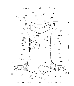
Figures 6A and 6B show front and rear coronal views of a wearer
showing where the low motion zone of the wearer is located. The low motion
zone is delineated by the shaded zones in the
.k,
WO 94/28842 PCT/US94/05788
2163' ~~~ ~
drawings. As defined by the anatomy of the wearer, the "low
motion zone" is defined to mean the zone or area of the body which
despite dynamic movements remains substantially undeformed or
undergoes very little motion. As shown in Figure 6A, the low
motion zone is bounded by the arcuate line in the hypogastric
abdominal region connecting each anterior superior iliac spine,
"S", through the crease or fold created by the rectus abdominus
muscle, hereinafter the abdominal crease, "T". The abdominal
crease is typically the fold or flexion crease of skin or muscle
created by the abdomen when the wearer goes into a sitting
position. The low motion zone is bounded on each lateral side by
an arcuate line connecting the anterior superior iliac spine
through the perineum along the inguinal ligament under the gluteus
maximus (along the gluteal fold) to about the posterior inferior
iliac spine, hereinafter the leg crease, "L". As shown in Figure
6B, the low motion zone is bounded on the posterior of the wearer
by the line connecting the posterior inferior iliac spine over the
gluteous maximus and along the lumbar curve of the back, "R" (the
small of the back). For purposes of the present invention, the
low motion zone also includes the zone or area of the gluteous
maximus (although not shaded in Figure 6B) despite the fact that
the gluteous maximus undergoes some dynamic motion since the
forces generated in this zone caused by the wearer's movements
tend to push up the absorbent core over the buttocks into the
lumbar curve to enhance the fit of the absorbent core and the
diaper rather than degrade such fit.
Figure 5 shows a plan view of a preferred shape for the
absorbent core 28 of the present invention. The shape of the
absorbent core is designed so that the absorbent core fits
substantially within the low movement, low distortion area (the
low motion zone) of the anatomy of the wearer. This anatomically
low motion zone-fitting absorbent core results in better fit, less
distortion and movement of the absorbent core during wear, less
bunching and roping of the core materials, and greater wearer
comfort and mobility. Superior fit is achieved with this
absorbent core design because the shape is matched to the wearer's
anatomy so that there is less gapping, bunching and slumping of
the absorbent core.i Sustained dynamic fit is achieved because the
SUBSInI~fE SN~Ef (RULE 26)
3310 94/28842 PCT/US94/05788
19
absorbent core is designed to cover those parts of the wearer's
anatomy that are subject to the least movement or change in shape
during wear such that fit can be controlled from the initial
fitting of the diaper on the wearer to taking the diaper off after
being soiled. Further, because the absorbent core is designed to
fit below or into the abdominal crease, the wearer's stomach has a
reduced tendency to push the absorbent core down and cause the
diaper to sag. Thus, the absorbent core remains substantially
within the low motion zone of the wearer. Since the absorbent
core is subjected to less dynamic forces caused by wearer
movements because the absorbent core is within the low motion
zone, the absorbent core also has less of a tendency to slump or
rope. Wearer comfort and mobility is improved due to the
decreased bulk of the absorbent core and the fact that the stiffer
materials of the absorbent core are not positioned in zones
subject to wearer movement.
The absorbent core 28 is shown in Figure 5 to comprise a
front section 100, a back section 102 contiguous with the front
section 100, a front waist edge 84, a back waist edge 86, and side
edges 98. The absorbent core 28 additionally has a lateral
centerline designated 104 and a longitudinal centerline designated
106. The front section 100 and the back section 102 extend,
respectively, from the front waist edge 84 and back waist edge 86
toward the lateral centerline 104 to the point corresponding to
the centerpoint of the arcuate leg cut outs of the side edges 98,
which is designated the crotch point 108.
As shown in Figure 5, in order to securely fit below or at
the abdominal crease of the wearer, the front waist edge 84
preferably has a substantially arcuate concave shape. As used
herein, the term "arcuate" refers to lines other than a straight
line although certain segments of the line may be straight line
segments. The term "concave" is used to denote an arcuate line
wherein the normals to the curve converge. The arcuate concave
shape of the front waist edge 84 generally corresponds to the
abdominal crease and is defined in an anatomical sense by three
points on the front waist edge corresponding to three points on
SUBS1rt11rE SHEkT (RbCE 26)
WO 94/Z8842 PCT/US94/05788
2~63'~ 38 20
the wearer. The two points of the front waist edge 84 farthest
away from the lateral centerline 104 adjacent the side edges 98
correspond to a point adjacent each anterior superior iliac spine
of the wearer. Thus, these two points are designated "hip points"
110. The third point is the point along the longitudinal
centerline 106 of the absorbent core 28 generally in line with the
navel of the wearer typically defining the lower point on the
abdominal crease of the wearer. This point is designated the
"abdominal point" 112. It has been found that the hip points 110
and the abdominal point 112 have certain defined dimensions and
relationships that do not vary significantly across wearers in
comparable weight ranges. The hip points 110 are laterally spaced
from another by a lateral distance, "H", less than or equal to
about the lateral distance between the anterior superior iliac
spines of the intended wearer. The abdominal point 112 is
longitudinally spaced inward from the hip points 110 by ~a
longitudinal distance, "D". It has been found that the ratio
(H:D) of the lateral distance between the hip points 110, H, to
the longitudinal distance between the hip points 110 and the
abdominal point 112, D, should fall within a certain specified
range in order for the front waist edge 84 to follow the abdominal
crease of the wearer. The ratio H:D is preferably between about
6:1 and about 9:1, more preferably between about 7:1 and about
8:1. The distance between the hip points 110 can be easily
selected based on targeted wearers and is preferably between about
14 cm and about 24 cm for wearers ranging from about 9 kgs to
about 21 kgs. A table of ranges of hip point distances for given
sizes of contemplated wearers is: birth - 5 kgs: 6 cm - 12 cm; 6
kgs - 9 kgs: 11.4 cm - 17.6 cm; 10 kgs - 13 kgs: 14.5 cm - 18.8
cm; 14 kgs - Z1 kgs: 16.8 cm - 24 cm. While the curve connecting
the hip points 110 and the abdominal point 112 can be any desired
shape including straight line segments, it is preferred that the
shape of the curve generally follow the curve of the abdominal
crease. It has been found that the curve following the abdominal
crease is generally an arc having a radius sufficient to fit the
hip points 110 and the abdominal point 112. Using curve fitting
techniques, a planar curve (rotated 29' into the x-y plane of the
suasmurE sH~r ~Ra~E ~sa
.,~0 94/28842 ~~ PCT/US94/05788
21
absorbent core) which has been found to approximate the arc of the
abdominal crease is a polynomial curve having the equation: y =
1/(a+bx2) wherein the coefficients a and b are preferably: a =
0.45763285 and b = -0.021195617.
The shape of the side edges 98 of the absorbent core 28 are
designed to provide a leg cut-out to fit at or within the leg
creases of the low motion zone and a portion to preferably fit
over the buttocks into the lumbar curve of the back. The side
edges 98 thus each have a leg segment 114 and a buttocks segment
116.
The leg segment 114 has a substantially arcuate concave shape
to fit within the leg creases. Along the arcuate curve forming
the 1 eg segment 114 i s a poi nt designated the "crotch poi nt" 108
which corresponds to the narrowest portion of the absorbent core
28 in the leg segments 114. While the curve forming the leg
segment 114, including the crotch point 108, can be any desired
shape including straight line segments, it is preferred that the
shape of the curve generally follow the curve of the leg crease.
It has been found that the curve is generally an arc having a
radius sufficient to fit the crotch point 108 through the leg
creases. Using curve fitting techniques, a planar curve (rotated
31' into the x-y plane of the absorbent core) which has been found
to approximate the arc of the leg crease is a polynomial curve
having the equation: y = a+bx+cx2+dx3+ex4+fx5+gx6 wherein the
coefficients a, b, c, d) e, f, and g are preferably: a =
-0.02015642, b = 0.02621513, c = 0.055790377, d = -0.03472119) a =
0.034448752, f = 0.000858783, and g = -0.0022505.
In order to provide optimum fit of the absorbent core 28 in
the low motion zone, the crotch points 108 are preferably
positioned more toward the front of the absorbent core 28 such
that the front section 100 is preferably shorter in longitudinal
length than the back section 102. The front section 100 will thus
fit low on the wearer to fit below or at the abdominal crease
while the back section 102 preferably extends over the buttocks
into the lumbar curve of the back. Therefore, the crotch points
108 are preferably positioned forward of the lateral centerline
104 of the absorbent core 28. The ratio of the longitudinal
suesnrurF sH~ (~d~ zs)
WO 94/28842 PCT/US94/05788
22
1 ength of the back secti on 102 to the 1 ongi tudi nal 1 ength of the
front section 100 is thus preferably greater than about 1:1.
The lateral width of the absorbent core 28 between the crotch
points 108, the crotch width, can also be important in providing
improved fit on the wearer. While the crotch width can vary
widely, it is preferred that the crotch width be narrow enough to
provide a comfortable fit on the wearer as well as optimal
absorbency. It is preferred that the crotch width be small so
that the absorbent core not bunch when the wearer's legs are
closed. However, reducing the crotch width reduces the amount of
absorbent material available in the zone of typical liquid
deposition. If highly absorbent materials are used that provide
sufficient capacity in this portion of the absorbent core, the
crotch width can be greatly reduced so that the crotch width is
small enough so that the absorbent core comfortably fits between
the leg creases when the legs of the wearer are closed.
Nevertheless, with most absorbent materials commonly used in
diapers or other absorbent articles, the crotch width may need to
be wider than the width of the wearer's body with the legs
together so that the absorbent core will still have sufficient
absorptive capacity. The shape of the leg segments, however,
allow the side edges to conform to the low motion zone leg creases
with minimal bunching and distortion. In alternative embodiments
(and especially with stiffer absorbent materials), the absorbent
core may be provided with means for providing enhanced bunching of
the core material such as predisposed score lines, notches, or
cut-outs of material. For the absorbent cores depicted in the
drawings, it has been found that the crotch width should
preferably be no greater than about 3 inches (7.5 cm), more
preferably between about 1 1/2 inches (3.78 cm) to 2 1/2 inches
(6.35 cm), most preferably about 2 inches (5 cm).
The buttocks segment 116 of the side edge 98 is contiguous
with the leg segment 114 and comprises that portion of the side
edge 98 extending from the leg segment 114 to the back waist edge
86. The buttocks segment 116 can be any desired shape.
Preferably, the buttocks segment 116 is designed so that the
buttocks segment 116 fits over the buttocks of the wearer into the
~u~nru~ s~~ t~a« 2s~
..1Y0 94/28842 ~~ ~ ~ PCT/US94/05788
23
lumbar curve of the back. In the preferred embodiment shown in
Figure 5, the buttocks segment 116 is essentially rectilinear (a
straight line) and parallel to the longitudinal direction. The
buttocks segment 116 is preferably rectilinear to allow wider
elastic side panels in the back waist region.
The back waist edge 86 of the absorbent core 28 may also have
a number of different shapes. For example, the back waist edge 86
may be arcuate or rectilinear or combinations of both. Further,
recesses may be cut out of the back waist edge 86 to control
bunching. In a preferred embodiment as is shown in Figure 5, the
back waist edge 86 is rectilinear and parallel to the lateral
direction.
Thus, the absorbent core 28 has an overall modified T-shape
that fits securely within the low motion zone of the wearer.
Figure 7A shows an alternative embodiment of an absorbent
core of the present invention. The absorbent core 728 has an
overall "whale" shape. The front waist edge 84 and the leg
segments 114 are identical to the absorbent core depicted in
Figure 5. The buttocks segment 116 of the side edge 98 has a
substantially arcuate convex shape to conform most closely about
the buttocks. As used herein, the term "convex" denotes an
arcuate line wherein the normals to the curve diverge. The back
waist edge 86 has a substantially arcuate convex shape so that the
absorbent core 728 fits conformably in the lumbar curve of the
back of the wearer and so that the absorbent core shape enhances
the formation of a primary line of tension directed at an angle on
the wearer's body.
Figure 7B shows a further alternative embodiment of an
absorbent core of the present invention. The absorbent core 728'
has a "modified whale" shape. The front waist edge 84 and side
edges 98 are identical to the absorbent core depicted in Figure
7A. The back waist edge 86 has a substantially arcuate convex
shape having a recess 710 wherein the recess 710 is formed by a
segment of the back waist edge 86 having an arcuate concave shape.
This recess enhances containment of fecal matter deposited within
the diaper.
SUBSTO1~E SHEEP (RdLE 26)
WO 94/28842 PCT/US94/05788
24
Figure 7C shows a still further alternative embodiment of an
absorbent core of the present invention. The absorbent core 728 "
has an overall "spade" shape. The front waist edge 784 has a
rectilinear shape generally parallel to the lateral direction.
The leg segments 114 are identical to the absorbent core shown in
Figure 5. Each buttocks segment 116 has an arcuate convex shape
to conform most closely about the buttocks. The back waist edge
86 has an arcuate convex shape so that the absorbent core 728 "
fits conformably in the lumbar curve of the back and so that the
absorbent core 728 " enhances the formation of a primary line of
tension directed at an angle on the wearer's body. The
longitudinal distance between the hip points 110 of the front
waist edge 784 is significantly shorter than the longitudinal
distance between the hip points of the absorbent core shown in
Figure 7A. This shape for the absorbent core 728 " provides
improved fit with reduced core bunching, especially at the front
and crotch of the absorbent core 728 " . The narrower crotch width
and front waist edge help in preventing core bunching from the
wearer's thigh movements. While the "spade" absorbent core 728 "
is useful in any of the containment assembly chassis shapes
disclosed herein, it has been found that the spade absorbent core
728 " is especially useful in an overall stretch chassis absorbent
article such as is shown in Figure 9.
Figure 7D shows an even still further alternative embodiment
of an absorbent core of the present invention. The absorbent core
728"' has a "modified whale" shape. The shape of the absorbent
core 728 " ' is similar to the whale absorbent core shown in Figure
7A except that the back waist edge 786 has a rectilinear shape
generally parallel to the lateral direction.
While the absorbent cores of the present invention may be
positioned in a containment assembly having various sizes and
shapes, it is preferred that the containment assembly also have
certain shapes to better fit the absorbent core into the low
motion zone of the wearer and reduce gapping of the containment
assembly. Thus, as shown in Figure 1, the containment assembly 22
preferably has a front end edge 56 having a substantially arcuate
concave shape and a back end edge 58 having a substantially
suss~mr~ sHE~r ~anu 2sa
(~ PCT/US94105788
~O 94IZ8842
arcuate convex shape. The arcuate concave shape of the front end
edge 56 allows the front end edge to be circumferentially disposed
about the stomach of the wearer and can preferentially be disposed
below the stomach so that the stomach will tend to not rub, abraid
or otherwise press outwardly against the front end edge. In a
particularly preferred embodiment, the stomach will overhang the
primary line of tension so that hoop stresses against the diaper
are controlled and sustained. The back end edge 58 preferably has
an arcuate convex shape so that when the diaper is worn, the back
end edge 58 is oriented diagonally downwardly across the hips
toward the front of the wearer. Thus, the back waist region 52 is
perched or otherwise supported through the small of the back so as
to prevent the containment assembly 22 from interfering with the
wearer's body during movements and to anchor the angled primary
line of tension about the wearer from the lumbar curve of the back
over the hips to under the abdominal crease. An arcuate convex
shape for the back end edge 58 also tends to reduce gapping in the
back waist region 52.
Figure 12 shows an alternative embodiment of a containment
assembly shape of the present invention wherein the back end edge
58' has a substantially arcuate convex shape with the curvature of
the back end edge being continuous from one longitudinal edge 54
to the other longitudinal edge 54. Thus, not only the central
region 60 of the containment assembly 22' has such an arcuate
convex shape, but also the back side panels 64 have the same
shape. This shape configuration for the back end edge enhances
the formation of a continuous primary line of tension at an angle
to the body of the wearer since the forces may resolved along the
continuous curve of the back end edge. Further, this shape for
the containment assembly 22' improves the application of the
diaper and the initial fit since the back end edge 56' tends to
fol l ow the curve of the shape of the body of the wearer and the
tape tabs naturally follow the angle of the landing member.
Figure 13 shows a further alternative embodiment of the
present invention of a containment assembly shape wherein the back
end edge 58" has an arcuate convex shape in the central region 60
and a separate arcuate convex shape in each back side panel 64.
SIIBStIIUTE SHEET (sdLE 26)
WO 94/28842 PCT/US94/05788
21s3'~ ~~ 26
With this overall shape, two inflection points, "I", are defined
in the back end edge 58" corresponding to the boundaries of the
central region 60 with the back side panels 64. This overall
shape of the back end edge 58" defines a "suspension bridge"
shape. In addition, the front end edge 56" has a suspension
bridge shape having an arcuate concave shape in the central region
60 and a separate arcuate concave shape in each front side panel
62 thereby defining two inflection points, "J". In a preferred
embodiment of this containment assembly 22", the curvature of the
central region 60 of the back end edge 58" matches the curvature
of the central region 60 of the front end edge 56". More
preferably, the curvature of the back side panels 64 matches the
curvature of the front side panels 62. With this arrangement, it
is easier to manufacture the diapers continuously on a high speed
production line since the side panels can be inwardly folded and
the diaper folded in half with only one cut needing to be made to
form the arcuate end edges such that the single cut forms both the
back end edge 58" of one diaper but also the front end edge 56" of
the subsequent diaper. In addition, there is no wasted material
and no scrap material that needs to be thrown away due to the
single cut at the end edges such that the cost of the end product
should be less. As will be recognized by those of skill in the
art, there may be other shapes for the back end edge and the front
end edge which allows such manufacturing ease.
It has been found that there is a preferred relationship
between the pl acement of the absorbent core 28 and the pl acement
of the back end edge 58 of the containment assembly 22 to provide
the preferred anchoring of the product about the wearer and the
fit of the absorbent core in the low motion Zone. As is shown in
Figure 4, this relationship is defined by two longitudinal
distances on the containment assembly 22. The first distance is
the longitudinal distance from the abdominal point 112 of the
absorbent core 28 to the lateral line connecting the crotch points
108 of the side edges 98 of the absorbent core 28. This front
length distance is designated "A". The second distance is the
longitudinal distance between the lateral line connecting the
crotch points 108 and a point on the back end edge 58 of the
SUBSUME SNEEf (RdLE 26)
WO 94/28842 ~'~ PCT/US94/05788
27
diaper on the longitudinal centerline 67. This back length
distance is designated "B". It has been found that the ratio of
the back length to the front length (B: A) is preferably greater
than about 1.5:1, more preferably between about 2.0:1 and about
3.0:1, with a target for most diapers of about 2.5:1. This ratio
between the back length, B, and the front length, A, allows the
back end edge 58 to be positioned in the lumbar curve of the back
and the front waist edge 84 of the absorbent core 28 to be
positioned at or below the abdominal crease of the wearer. Thus,
a line of tension (primary line of tension) can be developed
around the wearer from the lumbar curve of the back over the hips
to under the abdominal crease to anchor the product on the wearer.
As shown in Figure 6C, this ratio also defines an angle, a,
between the line connecting the lumbar curve of the back and the
navel, a lateral line with respect to the diaper, to a point below
the abdominal crease of greater than about 5°, typically from 5'
to about 60', preferably from about 5' to about 30', more
preferably from about 10' to about 20°, most preferably about 15'.
As discussed hereinafter, the closure system is designed to create
a line or zone of tension causing a hoop force connecting the
lumbar curve of the back over the hips to under the abdominal
crease to form the anchoring function.
The diaper 20 is provided with a closure system (closure
means) for anchoring the diaper about the wearer throughout the
diapers use so the diaper has a reduced likelihood to sag/gap and
slide/slip during use. The closure system provides a line or
lines (zone) of tension (hereinafter, the primary line of tension)
substantially about the perimeter of the low motion zone that
imparts anchoring forces to maintain the position of the diaper
throughout wearing. As shown in Figure 6C, the primary line of
tension is disposed at an angle, a, to the horizontal on the body
of the wearer (an angle to the lateral direction of the diaper)
such that the primary line of tension extends from around the
lumbar curve of the back (the small of the back) over the iliac
crest of the hips to below the line of the abdominal crease.
Thus, the primary line of tension is disposed in the zone of
minimal changing body dimension, a sustained wearing position
SUBSIiTUTE SHEET (RULE 26)
WO 94/28842 PCT/US94/05788
2163'~3~ 28
(i.e., the primary line of tension is not disposed over the
abdomen or the gluteous maximus which increase and decrease in
dimension during movement), such that the primary line of tension
stabilizes and maintains anchoring forces which maintain the
position of the diaper on the wearer such that the diaper is
unlikely to slide or slip downward during the entire time of use
due to the movements of the wearer or to the force of the
increased weight of the diaper when it is loaded. The angled
primary line of tension created by the closure system also imparts
an upward anchoring force on the diaper tending to pull the diaper
up on the body, and thus counteract the weight force of the loaded
diaper, since the primary line of tension has a vector component
in the longitudinal direction. The normal anchoring forces
created by the primary line of tension (another vector component
of the angled primary line of tension) anchor the diaper,
particularly the absorbent core, in the low motion zone since the
normal anchoring forces act compressively to push the absorbent
core toward the body. These normal anchoring forces thus assist
in maintaining the fit of the diaper as well as reducing leakage
since the absorbent core is maintained in close relationship with
the body. The angled primary line of tension also tends to reduce
redmarking since the anchoring forces are disposed in the low
motion zone such that the body dimension is not increasing or
decreasing along the primary line of tension which could cause red
marking. In an especially preferred embodiment of the closure
system of the present invention, the primary line of tension is
continuous about the back and hips of the wearer to further
enhance the magnitude of the anchoring forces. The overall design
of the containment assembly 22, the elastic waist feature 34 in
the back waist region 52 (the back waist feature), and the elastic
side panels 30 (particularly the activation of the elastic side
panels 30 at an angle) allow a continuous primary line of tension
to be provided in the diaper.
Since the primary line of tension is to be disposed at an
angle to the lateral direction to provide its anchoring function,
the closure system is designed to provide an angled closure
mechanism to insure such a primary line of tension is imparted to
SUBSII~ItIE SHEET (RtiLE 26)
WO 94128842 ~ PCT/US94/05788
29 ~~c~
the diaper. The closure system may thus comprise a number of
different fastening systems for providing an angled primary line
of tension. For example, the closure system may simply comprise a
primary fastening system. The closure system may additionally
anchor a portion of the elastic waist feature in the front waist
region, and, if desired, a portion of the elastic leg cuff. Thus,
the closure system may comprise a full length fastener system.
Examples of full length fastener systems are disclosed in U.S.
Patent 4,701,176 issued to Wilson, et al. on October 20, 1987.
Most preferably, as is shown in Figure 1, the closure system
comprises a dual tension fastening system designed to create the
angled primary line of tension as described herein and to
dynamically create/maintain tension, preferably another angled
line of tension, through the elastic waist feature 34 in the front
waist region 50 (hereinafter, front elastic waist feature) so that
the front elastic waist feature also has sustained dynamic fit.
As shown in Figure 1, the primary fastening system comprises
a securement member, preferably tape tab 36, disposed adjacent
each longitudinal edge 54 in the back waist region 52, and at
least one landing member 38 disposed in the front waist region 50.
Each securement member preferably comprises a tape tab 36 having a
first fastening component 37. The landing member 38 comprises a
complimentary second fastening component 39 engageable with the
first fastening component 37. An exemplary primary fastening
system wherein the first and second fastening components each
comprise mechanical closure elements comprising hook and loop
fastening materials is disclosed in U.S. Patent 4,963,140 entitled
"Mechanical Fastening Systems With Disposal Means For Disposable
Absorbent Articles" issued to Robertson and Scripps on October 16,
1990. A primary fastening system having combination
adhesive/mechanical closure elements is described in U.S. Patent
4,946,527 entitled "Pressure-Sensitive Adhesive Fastener and
Method of Making Same" issued to Battrell on August 7) 1990. In a
preferred embodiment of the present invention as is shown in
Figure 1, the primary fastening system comprises an adhesive tape
tab fastening system comprising a tape tab 36 having a first
fastening component 37 comprising an adhesive attachment layer,
SUBSItfUfE SNEET (ROLE 26)
WO 94/28842 PCT/US94/05788
,637 ~8 30
2
and a landing member 38 having a second fastening component 39
comprising a reinforcing strip 92 joined to the backsheet 26.
Examples of such adhesive tape fastening systems are disclosed in
U.S. Patent 3,848,594 entitled "Tape Fastening System For
Disposable Diaper" issued to Buell on November 19, 1974; and the
adhesive tape tabs, reinforcing strip, and indicia means disclosed
in U.S. Patent B1 4,662,875 entitled "Absorbent Article" issued to
Hirotsu and Robertson on May 5, 1987.
Each securement member of the primary fastening system is
intended to provide a fastening means for engaging the landing
member so as to provide a secure, preferably a variable
positioning, side closure for the diaper that anchors the
absorbent core in the low motion zone of the wearer. Thus, the
securement member comprises a fastening component. Each
securement member also preferably comprises a means for
positioning the fastening component adjacent the landing member so
as to achieve the side closure. Thus, the securement member may
comprise any of the well known configurations and means for
achieving a side closure on a diaper such as (i) a patch or strip
of a fastening component disposed to form a portion of the inner
surface of the diaper, an inner fastening member (e. g., U.S.
Patent 4,610,682 issued to Kopp on September 9, 1986; and U.S.
Patent 3,141,161 issued to Farris on July 21, 1964) or (ii) a tape
tab having a fastening component positioned thereon.
As shown in Figure 1, each securement member preferably
comprises a tape tab 36. The tape tabs 36 must be able to be
secured to the landing member 38 so as to provide a primary line
of tension through the diaper at an angle to the lateral
direction. Thus, the tape tab 36 is generally shaped and oriented
to allow the first fastening component 37 to engage the second
fastening component 39 of the landing member 38 so as to provide a
primary line of tension at an angle to the lateral direction,
preferably through the diaper substantially about the low motion
zone.
Figures 1 and 8 shows a preferred embodiment of a preferred
tape tab 36 of the present invention. The tape tab 36 is joined
to the backsheet 26 to create a fixed portion 122 (i.e., that end
SUBSTifIt~E SHEET (ROLE 26)
WO 94/28842 ~ PCTIUS94105788
31
of the tape tab joined to the diaper 20 during manufacture). The
tape tab 36 has another element which is the tab portion 124
(i.e., that end of the tape tab contiguous to the fixed portion
122 that is disposed so as to be capable of extending laterally
outwardly beyond the longitudinal edge 54 and that is grasped by
the diaperer in securing the diaper 20 on the wearer). The tab
portion 124 has a proximal edge 126 contiguous to the fixed
portion 122, a distal edge 128, and sidelong edges 130. The
proximal edge 126 has a top point 132 and a bottom point 134. The
distal edge 128 has an upper point 136 and a lower point 138. In
preferred embodiments of tape tabs of the present invention, the
tab portion 124 is shaped and oriented at an angle to the lateral
direction to insure the formation of the primary line of tension
at an angle to the lateral direction. Thus, the upper point 136
of the distal edge 128 is disposed at an angle to the lateral
direction from the top point 132 of the proximal edge 126, and
preferably the bottom point 134 of the distal edge 128 is disposed
at an angle (not necessarily the same angle) to the lateral
direction from the bottom point 134 of the proximal edge 126. In
the embodiment shown in Figure 8, the sidelong edges 130 are
curved to allow angled taping in order to follow the diaper
shape/build of the wearer, to create the angled primary line of
tension about the low motion zone to anchor the diaper on the
wearer, and to allow the diaperer to conveniently apply the tab
portion 124 on the landing member 38 so as to accommodate the
diaper design. Further, the curved shape of the sidelong edges
130 of the tab portion 124 allows high tape placement in the back
waist region 52 yet allows low tape placement on the landing
member 38 to minimize marking of the stomach, hips and legs of the
wearer to improve the comfort of the diaper for the wearer. The
tab portion 124 also accommodates the leg of the wearer in that if
the tape tab was positioned too low on the product, marking could
occur on the legs of the wearer which would negatively impact
comfort and fit.
It has been found that the angle formed between the proximal
edge 126 of the tab portion 124 and the distal edge 128 of the tab
portion 124 should be less than about 30°, preferably between
SUBS11TU~E SNEET (RULE 26)
WO 94/28842 PCT/US94/05788
~163'~3~ 32
about 5° and about 30°, more preferably between about 10°
and
about 25°, most preferably about 20°, to approximate the angle
of
fit of the diaper on the wearer. A tab portion 124 having an
angle greater than about 30° tends to cause the primary line of
tension to be very narrow through the tape tab which may result in
tape rotation or product rotation due to the non-resolved forces
set up i n the tape tab. The tape tab woul d al so not fol l ow the
angle of the product to set up the angled primary line of tension
of approximately 15°.
In a preferred embodiment of the tape tab 36 as shown in
Figure 8, the fixed portion 122 is between about 28 mm and about
30 mm long in the lateral dimension, the tab portion 124 is about
35 mm (1.375 in) long in the lateral direction, and the overall
width of the tape tab in the longitudinal direction is about 29 mm
(1.125 in). The angle between the proximal edge top point 132 and
bottom point 134 and the distal edge upper point 136 and lower
point 138, respectively, of the tab portion 124 is about 20° so
that the longitudinal distance between the top point 132 or the
bottom point 134 of the proximal edge 126 and the upper point 136
or lower point 138 of the distal edge 128 is about 13 mm (0.5 in).
(The distal edge 128 of the tab portion 124 may also be provided
with rounded corners to eliminate the possibility of harsh corner
edges contacting the wearer's skin so as to prevent stomach and
leg red marking.)
As shown in Figure 2, the preferred tape tab 36 also
comprises a release portion 140 joined to the topsheet 24. The
release portion 140 allows the tab portion 124 to be inwardly
folded during manufacture to protect the first fastening component
37 (adhesive attachment layer) from contamination or delamination
prior to use. The tab portion 124 is preferably shorter in the
lateral direction than the release portion 140, preferably about 3
mm (1/8 in) in a preferred embodiment as shown in Figure 2, so
that it is easier for the diaperer to initially grasp the tab
portion 124. (Alternatively, the tab portion 124 may be longer in
the lateral direction so that the grip tab on the distal edge 128
of the tab portion 124 extends beyond the release portion 140.)
The release portion 140 extends inwardly from the longitudinal
SUBSTITUTE SHEET (RULE 26~
WO 94/28842 PCT/US94105788
33 C
edge 54, in certain embodiments preferably up to and juxtaposed
over a portion of the elastic side panel member 82 so that the
load carried by the tape tab 36 is transferred into the elastic
side panel member 82 resulting in more effective distribution of
the anchoring forces created by the closure system.
In alternative preferred embodiments of the present
invention, the tab portion 124 or the entire tape tab may be
applied to the contaiment assembly 22 at an angle to the lateral
direction to provide the angled primary tension line desired. For
example, a rectangular tape tab such as is known in the art or a
tape tab having any other shape may be rotated with respect to the
lateral direction when applied to the containment assembly such
that the tape tab is disposed at an angle to the lateral direction
of preferably between about 5' to about 30', preferably from about
15' to about 20', to provide an angled primary line of tension.
While such a tape tab will adequately work with many embodiments
of the present invention, it is not as preferred as the tape tab
36 shown in Figure 8.
The flexibility of the materials making up the various
portions of the tape tab has also been found to be important in
avoiding skin marking of the legs and waist of the wearer. Stiff
tape tabs have a tendency to mark the skin since they are not
flexible enough to bend or flex when the wearer moves and
generates forces against the tape tab. The flexibility of the
tape tabs is an especially important design parameter for the tape
tabs of the present invention due to the high tension created in
the diaper along the side panels because of the elastic side
panels 30 and the fit provided by the diaper 20. Thus, in an
especially preferred embodiment of the present invention, at least
the tab portion 124, and preferably the fixed portion 122 and the
release portion 140 are manufactured from materials which are
extremely flexible. While the flexibility of the tape tab
materials can be measured in a number of ways, it has been found
that there is a preferred test method for measuring the
flexibility of the tape tab materials. Using a Flexural Bending
Test, as defined hereinafter, each of the various portions of the
tape tabs, particularly the tab portion 124, should have a Bending
SUBS'tl~U1'E SNEET (~~~E~6)
1~2~6373~
34
Flexure Extension Force of less than about 50 gramsf, preferably less than
about 30 gramsf, more preferably less than about 20 gramsf.
Preferred materials for the tape tab comprise a polymeric material,
preferably a polyethylene film. Tape materials suitable for use as the tape
tabs are XPF-3062T"", XPF-3-014T"", Y-9376T"", or Y-9030T"" as are available
from
the Minnesota Mining and Manufacturing Company of St. Paul, Minnesota.
Preferred tape tabs including a pressure-sensitive adhesive for the first
fastening component are available from the Minnesota Mining and
Manufacturing Company under the code number XPF-3062T"". A preferred
release portion include that available from Minnesota Mining and
Manufacturing Company under the code number KS-0076T"'.
Figure 12 shows an alternative embodiment of a securement member
of the present invention. The securement member comprises an inner
fastening member 1200 positioned on the inner surface 48 of the back side
panels 64. The inner fastening member 1200 has a securement portion 1202
and a release portion 1204. The securement portion 1202 has a first fastening
component 1237 preferably comprising a layer of adhesive disposed on it to
form the side closure of the diaper. The release portion 1204 serves to
protect
the first fastening component 1237 from contamination prior to use of the
diaper. The securement portion 1202 is preferably folded over onto the
release portion 1204 during manufacture such that the user would release the
securement portion 1202 from the release portion 1204 prior to use. The
securement portion 1202 need not be joined to the back side panel 64 such
that only the securement portion 1202 need be folded over or the securement
portion may be secured to the back side panel such that the back side panel
along with the securement portion need to be folded over onto the release
portion 1204. As shown in Figure 12, the securement member 1202 is
positioned laterally outwardly from the release portion 1204; however, the
position of each may be reversed, if desired. Figure 12 also shows that the
inner fastening member 1200 has a generally rectangular shape and is
disposed at an angle to the lateral direction to enhance the formation of the
angled primary line of tension. Alternatively,
~r~:~~,~,,
"... ,~; ~a " ~,
k '
WO 94/28842 , ~ PCT/US94/05788
35 '
the inner fastening member may have any other shape, including the
shape of the tab portion and release portion of the tape tab shown
in Figure 1 and Figure 8. The inner fastening member 1200 may
alternatively not be disposed at an angle, while the first
fastening component 1237 may form such an angle.
In an alternative embodiment of the tape tabs described
herein, the fixed portion and the release portion may comprise the
same element such as that shown in Figure 12 except that the tab
portion extends laterally outwardly from the longitudinal edge.
Thus, the fixed portion is secured to the inner surface of the
containment assembly and coated on its exposed surface with a
release coating such that the tab portion may be laterally
inwardly folded by the manufacturer to protect the first fastening
component. The advantage of such a construction for the tape tabs
of the present invention is that only one layer of tape tab
material is joined to the containment assembly in the portion of
the back side panel containing a portion of the tape tab such that
the flexibility of this portion of the back side panel is enhanced
to thereby reduce the possibility of skin marking of the wearer.
The first fastening component 37 of the securement member
forms the closure between the securement member and the
complementary second fastening component 39 of the landing member
38. Thus, the first fastening component 37 provides a means for
engaging the complementary second fastening component 39 of the
landing member 38 to maintain the first waist region 56 and the
second waist region 58 in an overlapping configuration to provide
a secure side closure for the diaper 20. Further, it is preferred
that a diaper fit a range of different size wearers and that the
fastening system be simple and easy to use. Therefore, the
fastening components should allow for variable positioning of the
zone of closure so that the diaper may fit a range of sizes of
wearers while also being simple to fasten with minimal effort.
The fastening components thus preferably comprise any of the well
known attachment means for achieving an adjustable positioning
closure as defined hereinafter. Examples of such adjustable
positioning attachment means include an adhesive attachment layer
such as pressure-sensitive adhesives as are known in the art,
SUBS~11I~E SNEEf f RdLE 26)
WO 94/28842 PCT/US94/05788
36
mechanical closure elements such as hook fastening materials or
loop fastening materials, cohesive materials as are known in the
art, or a combination of adhesive/mechanical closure elements,
each as hereinafter described with respect to the waist closure
system.
The first fastening component 37 is disposed on the
securement member such that it may be a separate member joined to
and associated with the securement member or a unitary member with
the securement member. For example, the topsheet 24 or the
backsheet 26 may be manufactured from a material that mechanically
engages the landing member 38 (the topsheet 24 or the backsheet 26
being a unitary fastening component). Alternatively, a discrete
patch or strip of material may be joined to the securement member
(a separate fastening component). Preferably, the first fastening
component 37 is a separate material, such as an adhesive
attachment layer or a mechanical closure element, positioned on
and joined to the tape tab 36. The first fastening component 37
preferably comprises an adhesive attachment layer coated on the
tab portion 124 to form the fastening surface of the tape tab 36.
In addition, the first fastening component 37 may be
positioned anywhere on the securement member. For example, the
first fastening component 37 may be positioned in the back side
panels 64 adjacent the longitudinal edges 54. (Exemplary examples
of this construction are shown in U.S. Patent 4,610,682 issued to
Kopp on September 9, 1986; and in U.S. Patent 3,141,161 issued to
Farris on July 21, 1964; and Figure 12.) When the securement
member comprises a tape tab, the first fastening component 37 is
preferably positioned either on all or at least a portion of the
tab portion 124. The first fastening component 37 may comprise a
combination adhesive/mechanical closure element having an adhesive
attachment layer and a mechanical closure element disposed on
another area of the tab portion 124. An exemplary embodiment of
this configuration is disclosed in the hereinbefore referenced
U.S. Patent 4,963,140 issued to Robertson on October 16, 1990.
The landing member 38 of the primary fastening system
provides a means for securing itself to the securement member to
provide a side closure and to maintain the front waist region 50
SUBSTiME SHEE'~ (Rbl.E 26)
WO 94/28842 ~~ PCT/US94/05788
37
and the back waist region 52 in an overlapping configuration. The
landing member 38 may be disposed anywhere on the diaper 20 so
long as it can engage the securement member so as to provide the
side closure and, preferably a variable positioning side closure.
For example, the landing member 38 may be disposed in the back
waist region 52, in the front waist region 50, or in any region or
zone or on any element of the diaper 20, which is disposed to
engage the securement member 42. Because the landing member 38
determines the location of where the securement member 42 should
be placed for optimum fit, the landing member 38 is preferably
designed so as to allow variable positioning of the side closure
so that the diaper may fit a range of sizes, so that an overlap
between the front waist region 50 and the back waist region 52 is
achieved, so that an angled primary lines) of tension is
established through the diaper to anchor it on the wearer, and
preferably so that when the side closure is formed the attachment
components of the waist closure system engage each other such that
the formation of the side closure also passively forms the waist
closure.
The landing member 38 can assume varying sizes and shapes.
In a preferred embodiment of the diaper 20 as illustrated in
Figure 1, the landing member 38 comprises a reinforcing strip 92
having a modified chevron shape so as to create the angled primary
line of tension of the present invention.
The landing member 38 comprises a fastening component (second
fastening component 39) engageable with the fastening component of
the securement member (first fastening component 37). Thus, the
fastening component of the landing member 38 (second fastening
component 39) may be manufactured from a wide range of materials
and configurations capable of securely engaging the fastening
component of the securement member (first fastening component 37).
The second fastening component 39 may either be a discrete,
separate element or elements joined to the diaper 20 and/or a
unitary piece of material with an element of the diaper 20. The
second fastening component 39 may thus comprise, for example, a
portion of the backsheet 26. As shown in Figure 1, the second
fastening component 39 preferably comprises a reinforcing strip 92
SURE SHEEP Rd~.~~2~
SUBSTiME SHEE'~ (Rbl.E 26)
3s - 2163738
joined to the external surface of the backsheet 26 in the front waist region
50.
The second fastening component 39 is secured to the backsheet 26 preferably
by an adhesive attachment means (not shown) as have been herein discussed.
(In an alternative embodiment of the present invention, the second fastening
component comprises a portion of the backsheet with a reinforcing strips)
secured to the internal surface of the backsheet (i.e., an internal
reinforcement
system).)
When the first fastening component 37 comprises a mechanical closure
element, the second fastening component 39 also comprises a mechanical
closure element. Thus, when the first fastening component 37 comprises a
hook fastening material, the second fastening component 39 preferably
comprises a loop fastening material. When the first fastening component 37
comprises an adhesive attachment layer, the second fastening component 39
of the landing member 38 preferably comprises a reinforcing strip 92 and/or
the backsheet 26. In a preferred embodiment of the present invention as
shown in Figure 1, the second fastening component 39 preferably comprises a
reinforcing strip 92 releasably engageable with the adhesive attachment layer
of the tape tabs 36. The reinforcing strip 92 may comprise any of a number of
materials. The reinforcing strip 92 preferably comprises a sheet of biaxially
oriented polypropylene film.
The reinforcing strip 92 is also preferably provided with indicia means
144 for aiding the diaperer in fitting the diaper to a wearer to obtain
optimal
waist fit and leg opening fit. The indicia means 144 may be any type of lines,
patterns, ornamental designs, symbols, script, color codes, or other markings
which have the capability, either inherently or with additional denotation, to
aid an individual fitting the diaper to the wearer to promptly locate the
desired affixation points for a particular tape tab fastener. Such indicia
means 144 are more fully described in U.S. Patent B14,662,875 entitled
"Absorbent Article' which issued to Hirotsu and Robertson on May 5, 1987.
Indicia means of the present invention are preferably disposed in rows
disposed at an angle to the lateral direction, preferably at the same angle as
the tape
~; s j ~ ~','.
e... ~Q ~2~6373~
tabs 36, to allow angled fastening of the tape tab for optimized fit and for
providing an angled primary line of tension. The indicia means 144 comprise
a combination of different geometric shapes, colors, and objects, for example,
rows and columns of teddy bears.
In a preferred embodiment of the present invention as is shown in
Figure 1, the closure system additionally comprises a waist closure system for
providing a waist closure adjacent the front end edge 56 of the diaper 20. The
waist closure anchors a portion of the span of the front end edge 56. Further,
when the diaper 20 comprises a front elastic waist feature, the waist closure
dynamically creates/maintains tension through the front elastic waist feature
(i.e., through the elasticized waistband portion of the unitary
waistcap/waistband 70). An exemplary example of a waist closure system is
described in Canadian Patent Application Serial No. 2,103,272 entitled,
"Absorbent Article With Fastening System Providing Dynamic Elasticized
Waistband", filed by Weil, et al. on June 8, 1992.
The waist closure anchors a portion of the span of the front end edge
56, preferably a portion of the extensible span of the front elastic waist
feature, preferably the elasticized waistband portion of the unitary
waistcap/waistband 70. (i.e., The first and second attachment components of
the waist closure system act to anchor the positional relationship of the
elasticized waistband portion with the elastic side panels 30.) The positional
relationship of the elasticized waistband portion with the elastic side panels
(i.e., the geometric relationship between the anchor zones of the first
attachment components 40) establishes a defined waist circumferential
25 dimension adjacent the front end edge 56 which is distinct (longitudinally
spaced) from the circumferential dimension established by the side closure
formed by the primary fastening system. This distinct, defined waist
circumferential dimension creates/ maintains the required fit dimensions) at
the upper extremities (adjacent the front end edge 56) of the diaper 20. Thus,
30 the waist closure system of the present invention can also be beneficial
for use
on diapers not
,,-,, ~. .
WO 94/28842 PCT/US94/05788
~63'~ '~'~ a0
employing an elastic waist feature (e.g., a waistshield or a
nonextensible waist feature) so as to maintain a nonextensible fit
at the front end edge 56 (upper edge) of the diaper 20. The
anchoring also provides a means for transferring shear forces
(tensions) between the front elastic waist feature and the elastic
side panels so as to enhance the initial pretension created within
the front elastic waist feature.
The waist closure also creates/maintains a lines) of tension
through the front elastic waist feature (i.e., the waistband
portion 71 of the unitary waistcap/waistband 70). The waist
closure contributes some portion of an initial pretension (having
a vector component in the lateral direction) within the
elasticized waistband portion that allows the elasticized
waistband portion to snugly fit against the wearer's waist when
initially fitted. The elasticized waistband portion maintains,
during use, some portion of the pretension created within it by
the waist closure. Since the elasticized waistband portion
maintains some portion of the pretension created within it, the
elasticized waistband portion can repeatedly elastically expand or
contract with the motions of the wearer so as to snugly sustain
the fit of the diaper against the wearer's waist throughout use.
In particular, during wearing conditions, the elasticized
waistband portion, in order to follow the movements of the
wearer's waist, may have to contract to its untensioned state
(i.e., the pretension goes to zero); however, because the
attachment components remain engaged, the pretension will be
reestablished within the elasticized waistband portion with
further movement and activity by the wearer. (This is in contrast
to most conventional elastic waist features that are not
pretensioned such as to not be able to further contract to
dynamically fit the wearer.) This initial pretensioning and
maintenance of the tension thus results in reduced gapping and
better sustained fit of the front elastic waist feature. Further,
the lateral tensions) created/maintained by the waist closure
provide restoring forces within the front elastic waist feature
that reduce or counteract the incidence of waistband "rollover".
Thus, the waist .s~io~ure_svstem provides a closure about the waist
SUBSIt~UiE SHEET (RdLE 26)
WO 94/28842 PCT/US94/05788
~1~~'~~~
of the wearer to improve the initial and dynamic fit and
containment characteristics of the diaper.
As shown in Figure 1, the waist closure system comprises at
least one, preferably a pair of, first attachment components 40
and at least one second attachment component 42. As shown in
Figure 1, the first attachment components 40 are longitudinally
aligned with the front elastic waist feature, preferably the
elasticized waistband portion of the unitary waistcap/waistband
70, so that the tensions dynamically created/maintained by the
waist closure system extends in and through the front elastic
waist feature during use. Further, the attachment components of
the waist closure system are longitudinally spaced from the tape
tabs and the landing member of the primary fastening system to
provide a distinct, defined waist circumferential dimension for
the diaper and two distinct zones of tension. The line or zone of
tension created by the primary fastening system (primary line Qf
tension) secures the diaper on the wearer while the line or zone
of tension dynamically created/maintained by the waist closure
system dynamically maintains the upper waist closure during wear.
At least two anchor zones are created by the attachment
components when the waist closure is formed. These two anchor
zones are laterally spaced from each other with all or at least a
portion of the front elastic waist feature positioned between the
anchor zones. The lateral spacing of these anchor zones can be
achieved in a number of different ways. For example, the lateral
spacing between the anchor zones can be fixed by providing the
waist closure system with a pair of first attachment components
laterally spaced from each other and a second attachment
components) that allows adjustable positioning with the first
attachment components (e.g., the second attachment components) is
relatively wide). In this embodiment, since the lateral spacing
of the first attachment components is fixed, the lateral spacing
of the first attachment components determines and sets the lateral
spacing of the anchor zones. In an alternative embodiment, the
waist closure system may comprise a pair of second attachment
components laterally spaced from each other and a first attachment
components) that allows adjustable positioning with the second
SUBSmIITE SNEET (,RATE 26)
WO 94/28842 PCT/US94/05788
2~63'~3~s 42
attachment components (e.g., the first attachment component is
relatively wide). In this embodiment, the lateral spacing of the
anchor zones is determined by the size of the waist of the wearer
and the overall dimension/shape of the diaper since the location
of where the second attachment component 42 engages the first
attachment components 40 depends upon the overlap of the back side
panels 64 with the front side panels 62.
The preferred lateral spacing of the anchor zones is designed
to allow passive activation of the waist closure when the side
closure is formed, and to assure the maintenance of normal forces
applied to the waist of the wearer to decrease the tendency of the
front elastic waist feature to nonrecoverably rollover while
providing an effective amount of stretch in the front elastic
waist feature that improves the fit and containment of the diaper
at the waist. In order to maintain normal forces within the front
elastic waist feature that provide for recovery of the front
elastic waist feature and minimize flipping out of the tensioned
front elastic waist feature (i.e., nonrecoverable rollover), the
lateral spacing of the anchor zones would desirably be kept to a
minimum. However, in order to provide a maximum amount of stretch
in the front elastic waist feature, the lateral spacing of the
anchor zones would be desirably chosen to be at a maximum.
Therefore, the lateral spacing of the anchor zones is thus chosen
so as to balance the need for maintaining the normal forces with
the need for providing an effective amount of stretch in the front
elastic waist feature.
In the diaper embodiment shown in Figure 1, the lateral
spacing between the anchor zones (between the first attachment
components 40) is at least about 25 mm. More preferably, the
1 ateral spaci ng i s at 1 east about 50 mm. The 1 ateral spaci ng of
the first attachment components is most preferably between about
100 mm and about 200 mm. The lateral spacing of the anchor zones
is determined by measuring the distance from the innermost line of
securement (i.e., that line closest to the longitudinal centerline
67) of one anchor zone to the innermost line of securement of the
other anchor zone with the front elastic waist feature in its
contracted state. Thus, in the embodiment illustrated in Figure
SUBSTtIUTE SHEET (RdLE 26)
~ WO 94/28842 ~ PCT/US94/05788
43
1, the lateral spacing is determined by measuring the distance
from the innermost edge of one of the first attachment components
to the innermost edge of the other first attachment component.
Each attachment component comprises a fastening means that
engages a complementary fastening means for providing a waist
closure, preferably a variable positioning, passively activated,
waist closure. As used herein, the term "variable positioning"
closure refers to a fastening system wherein at least one of the
positions of the components can widely vary so as to allow the
user to form a closure at a number of different locations. Thus,
for example, one of the components may have a fixed location on
the diaper (e. g., the lateral spacing between the first attachment
components is fixed so as to provide for the pretensioning of the
front elastic waist feature and the passive activation of the
waist closure) while the other component allows for variable
locations of attachment to the fixed component. This is in
contrast to a "fixed" positioning closure which requires both of
the mating elements to be fixed in position such that the
components must be joined at a specific location each time the
closure is formed (e. g., snaps and buckles). The waist closure
system also provides a passively activated waist closure. By
"passively activated", it is meant that a functional waist closure
is achieved with little or no additional effort by the diaperer
after a suitable initial body/leg fit (side closure) is achieved
using the primary fastening system. Passive activation of the
waist closure system requires the attachment components to not
only engage each other so as to provide a secure anchor with
little or no additional effort but also to be positioned on the
diaper in an arrangement that creates/maintains the tensions
within the front elastic waist feature.
As shown in Figure 1, the attachment components preferably
comprise mechanical closure elements. As used herein, the term
"mechanical closure elements" describes fastening means which
mechanically engage each other for providing a variable-position
closure. Thus, the mechanical closure elements may comprise any
of the well known means for achieving a variable-position closure
SUBSIIiUTE SHEET (RdtE 26)
~2~63738
44
by mechanical engagement such as VELCROT"~ or other hook and loop
fastening materials.
When the first attachment component 40 comprises a mechanical
closure element, the second attachment component 42 may comprise
"identical" complementary mechanical closure elements or "distinct"
complementary mechanical closure elements. As used herein, the term
"identical" complementary mechanical closure elements is used to define
mechanical fastening systems wherein the engaging elements of the first
component and the second component comprise the same configuration or
structure that are interlocking. Examples of such systems are described in
U.S. Patent 4,322,875 entitled "Two Strip Materials Used For Forming
Fasteners" issued to Brown, et al. on April 16, 1982. The term "distinct"
complementary mechanical closure elements is used herein to define
mechanical fastening systems wherein the first component is different from
the second component but is engageable therewith such as a hook fastening
material and a loop fastening material. For example, if the second attachment
component comprises a loop fastening material then the first attachment
component will comprise a hook fastening material and vice versa.
As used herein, the term "hook fastening material" is used to
designate a material having engaging elements. Thus, the hook fastening
material may also be referred to as a male fastener. It should also be
understood that the use of the term "hook" should be non-limiting in the
sense that the engaging elements may comprise any shapes as are known in
the art so long as they are adapted to engage a complementary mechanical
closure element such as a loop fastening material or another hook fastening
material.
The hook fastening material is preferably intended to mechanically
engage fibrous elements of a loop fastening material so as to provide a secure
closure. Thus, a hook fastening material according to the present invention
may be manufactured from a wide range of materials. Suitable materials
include nylon, polyester, polypropylene, or any combination of these
materials, or other materials as are known in the art. A suitable hook
fastening material comprises a number of shaped engaging elements
~~,,~~ ~;.~f ~.~C, J.:.
45
projecting from a backing such as the commercially available material
designated "SCOTCHMATE" brand No. FJ3402 available from Minnesota
Mining and Manufacturing Company, St. Paul, Minnesota. Alternatively, the
engaging elements may have any shape such as hooks, "T's'", mushrooms, or
any other shape as are well known in the art. An exemplary hook fastening
material is described in U.S. Patent 4,846,815 entitled "Disposable Diaper
Having An Improved Fastening Device" issued to Scripps on July 11, 1989.
An especially preferred hook fastening material, as shown in Figure 1,
comprises an array of prongs formed of thermoplastic material. Hot melt
adhesive thermoplastics, in particular polyester and polyamide hot melt
adhesives, are particularly well suited for forming the prongs of the hook
fastening material. The prongs are preferably manufactured using a
modified gravure or a screen printing process by printing the thermoplastic
material in its molten state onto a substrate in discrete units, severing the
material in a manner that allows stretching of a portion of the thermoplastic
material prior to severance, and allowing the stretched molten material to
"freeze" resulting in prongs. This preferred hook fastening material and
methods and apparatus for making such a hook fastening material are more
fully detailed in U.S. Patent 5,058,247, entitled "Mechanical Fastening Prong"
issued to Thomas and Blaney on October 22, 1991.
A loop fastening material provides a plurality of fibrous elements that
engage the engaging elements of a hook fastening material. The loop
fastening material may be manufactured from a wide range of materials to
provide fibrous elements, preferably loops. Such suitable materials include
nylon, polyester, polypropylene, any combination of these materials, or other
materials as are known in the art. A suitable loop fastening material
comprises a number of fiber loops projecting from a backing such as the
commercially available material designated "SCOTCHMATE"T"' brand nylon
woven loop No. SJ3401T"' available from Minnesota Mining and
Manufacturing Company, St. Paul, Minnesota. Another commercially
available loop fastening material comprises a
,'~, J~ ~,
X2163738
46
tricot kn~ ~: i abric having a plurality of nylon filament loops projecting
from a
backing of nylon such a the commercially available material designated
"Guilford No. 16110"T"' available from Guilford Mills of Greensboro, North
Carolina. An exemplary inexpensive loop fastening material and a method of
making such a loop fastening material are described in U.S. Patent 5,032,122
entitled "Loop Fastening Material For Fastening Device and Method of
Making Same", issued to Noel and Scripps on July 16, 1991. A suitable loop
fastening material may also be a woven or nonwoven fabric or any other type
of fibrous material or loop material which are well known in the art.
Examples of nonwoven materials suitable for use as a loop fastening material
herein are discussed with respect to the materials useful as the topsheet 24
of
the diaper 20. In a preferred embodiment, the second attachment component
42 comprises a loop fastening material formed by the nonwoven material of
the topsheet 24.
The attachment components may alternatively comprise an adhesive
attachment layer (a layer of adhesive material). Adhesives useful in the
present invention are preferably pressure-sensitive adhesives formulated to
adhere to a surface at ambient temperature by applying only light pressure.
Particularly preferred adhesives for use herein as the adhesive attachment
layer are hot melt pressure-sensitive adhesives as are known in the art. An
exemplary hot-melt pressure-sensitive adhesive is a Kraton based adhesive
with tacifiers and other additives such as marketed by Findley Adhesives,
Inc. of Elm Grove, Wisconsin under the tradename Findley 990T"' or H-2085T"".
The attachment components may further comprise a combination
adhesive/mechanical closure element. For example, the attachment
components may comprise a combination fastener such as hook fastening
material and an adhesive attachment layer juxtaposed with the hook
fastening material or a mechanical closure element such as a hook fastening
material having a layer of adhesive coated over a portion of the base or the
hooks of the hook fastening material. An exemplary fastener having a
combination mechanical/adhesive system is the pressure-sensitive adhesive
WO 94/28842 PCT/US94/05788
47
fastener having a textured fastening surface such as is disclosed
in U.S. Patent 4,946,527 issued to Battrell on August 7, 1990.
The attachment components may alternatively further comprise
any other cohesive material or materials that are known in the art
for providing a variable positioning fastener capable of being
passively activated. For example, a cohesive strip or material
can be foams, rubbers such as crepe or latex rubbers, other
adhesives, or a high static vinyl material. A separable fastener
of a high static vinyl material is more fully described in U.S.
Patent 4,979,613 issued to McLaughlin & Kleinsmith on December 25,
1990.
While the attachment components preferably provide for
variable positioning and passive activation, in alternative
embodiments, the attachment components may comprise fixed position
and/or user activated fasteners. Examples of such fasteners
include snaps, hook and eye fasteners, studs, buttons, or the
like.
The attachment components may comprise a separate element
joined to the diaper or may be a unitary element with one of the
other components of the diaper. For example, the topsheet 24 may
be manufactured from a material (e.g., a nonwoven web), that is
capable of mechanically engaging the other attachment component
(e.g., a hook fastening material). Further, the backsheet 26 can
be formed from a web having a textured pattern with a layer of
adhesive coated over a portion of the backsheet surface to form a
combination mechanical/adhesive fastener (attachment component)
such as is shown in the hereinbefore referenced U.S. Patent
4,946,527 to Battrell. In each of these cases, the attachment
component is unitary with another component of the diaper.
Alternatively, the attachment component may comprise a discrete
strip or patch joined to the diaper. In a preferred embodiment
shown in Figure 1, each first attachment component 40 comprises a
discrete separate patch of a hook fastening material joined to the
backsheet 26 so as to form a portion of the outer surface 46 while
the second attachment component 42 is a unitary element comprising
a portion of the topsheet 24 in the second waist region 58.
SUBSTITUTE SHEET (RULE ~b~
WO 94/28842 PCT/US94/05788
48
Each first attachment component 40 comprises an about 12 mm
wide (i.e., generally perpendicular to the longitudinal centerline
67) by about 19 mm patch of a hook fastening material. The first
attachment components 40 are preferably positioned so as to have a
lateral spacing of about 171 mm. Each first attachment component
40 is also spaced longitudinally from the front end edge 56. If
the longitudinal spacing of the first attachment component
(measured from the front end edge 56 of the diaper to the closest
edge of the first attachment component 40) is too small, the first
attachment component may be too high on the diaper and be in a
position to contact the wearer's skin; if the longitudinal spacing
is too great, the first attachment component may be so low as to
allow some rollover of the front elastic waist feature. The first
attachment components are preferably spaced from about 3 mm (1/8
inch) to about 15 mm (5/8 inch) from the front end edge 56,
preferably from about 8 mm to about 10 mm. The hook fastening
material used for the first attachment components 40 preferably
comprises an array of thermoplastic prongs formed on a backing;
the prongs of each hook fastening material most preferably being
oriented with the engaging means at an angle to the lateral
direction corresponding to the curvature or differential
extensibility of the front elastic waist feature so that maximum
tensi on i s created i n the front el asti c wai st feature or to the
primary line of tension so as to be parallel to the primary line
of tension. The waist closure system also comprises a single
second attachment component 42 comprising a loop fastening
material formed by a portion of the nonwoven material of the
topsheet 24.
The diaper 20 additionally comprises a positioning patch 44
located subjacent the first attachment component 40. The
positioning patch 44 raises the first attachment component 40 in
the Z direction (thickness) to allow the first attachment
component 40 to come in better contact with the second attachment
component 42 and allow the waist closure system to more easily be
closed (with less effort). Thus, the waist closure system is more
effectively passively activated. The positioning patch 44 also
provides a zone of increased flexural stiffness that reduces the
SUBSTITUTE SHEET (RULE 25~
WO 94/28842 ~~ ~ PCT/US94/05788
49
tendency of the flexible front side panels 62 to fold over onto
the first attachment components 40 thereby occluding the hooks
from being secured during diaper application. Thus, the
positioning patch 44 can comprise any element that provides a Z
direction build up to the first attachment components 40. As
shown in Figure 1, the positioning patches 44 each comprise a
rectangular-shaped piece of material positioned subjacent the
first attachment component 40. While the positioning patches 44
may be positioned directly subjacent the first attachment
components 40, the positioning patches 44 are preferably
positioned between the topsheet 24 and the backsheet 26. In order
to provide a flexurally stiff circumference about the waist of the
wearer, the lateral edges of the positioning patches can be
abutted to or slightly overlapped with the side edges of the
material forming the front elastic waist feature. The positioning
patches 44 preferably comprise a 38 mm wide by 32 mm long patch of
elastomeric foam. More preferably, during manufacture of the
diaper, the positioning patches 44 are formed of the same material
as the elastic side panel member 82 with the elastic side panel
member 82 of one diaper and the positioning patch 44 of the
adjacent diaper being formed from the same segment of material
that is then cut after the diaper is completed. Thus, the
positioning patch 44 extends from the front end edge 56
longitudinally inward toward the lateral centerline 66.
In a preferred embodiment of the present invention, the
diaper 20 further comprises elastic features to provide improved
body conformity, fit, and comfort for the wearer. In one
embodiment, the entire containment assembly of the diaper
positioned outside of the area occupied by the absorbent core may
be elastically extensible to allow for expansion of the body of
the wearer in the zones of the wearer subject to movement during
wear. A preferred material for such an overall elasticated
product is the material described in U.S. Patent 5,032,120
entitled "Disposable Absorbent Article Having Improved Leg Cuffs"
issued to Freeland and Allen on July 16, 1991. The material
preferably comprises the three ply laminate described therein
comprising a~-cerr~ral laminate of elastomeric hot melt adhesive,
s ~i ::.
,.,
.; !i~ ~
y,.;
9~ ~ sy
50 - 2163738
such as that marketed by Findley Adhesives Corporation of Wauwautosa,
Wisconsin under the tradename 198-338, positioned between two outboard
lamina such as nonwoven fabrics. Alternatively, the material can be a stretch
laminate such as a zero strain stretch laminate as are described hereinafter.
Because of the economics of providing an overall elastomeric containment
assembly, the diaper 20 is preferably provided with specific elastic features
to
accommodate the extremities of the wearer. In particular, the diaper 20 is
provided with elastic side panels 30, elastic leg cuffs 32, and elastic waist
features 34.
As shown in Figure 2, the diaper 20 preferably comprises elastic leg
cuffs 32 for providing improved containment of liquids and other body
exudates and for accommodating movements of the wearer adjacent the legs.
Each elastic leg cuff 32 may comprise several different embodiments. (The
leg cuff can also be referred to as leg bands, side flaps, barrier cuffs, or
elastic
cuffs.) U.S. Patent 3,860,003 entitled "Contractable Side Portions For A
Disposable Diaper" issued to Buell on January 14, 1975, describes a
disposable diaper which provides a contractible leg opening having a side
flap and one or more elastic members to provide an elasticized leg cuff
(gasketing cuff). U.S. Patent 4,909,803 entitled "Disposable Absorbent Article
Having Elasticized Flaps" issued to Aziz and Blaney on March 20, 1990,
describes a disposable diaper having "stand-up" elasticized flaps (barrier
cuffs) to improve the containment of the leg regions. U.S. Patent 4,695,278
entitled "Absorbent Article Having Dual Cuffs' issued to Lawson on
September 22, 1987, describes a disposable diaper having dual cuffs including
a gasketing cuff and a barrier cuff. U.S. Patent 4,704,115 entitled
"Disposable
Waist Containment Garment' issued to Buell on November 3, 1987, discloses
a disposable diaper or incontinent garment having side-edge-leakage-guard
gutters configured to contain free liquid within the garment. U.S. Patent
5,032,120, entitled "Disposable Absorbent Article Having Improved Leg
Cuffs" issued to Freeland and Allen on July 16, 1991, discloses a disposable
diaper having unproved elastic leg cuffs. While
51 - 21 6 3 7 3 8
each elastic leg cuff 32 may be configured so as to be similar to any of the
leg
bands, gasketing cuffs, side flaps, barrier cuffs, or elastic cuffs described
above, it is preferred that each elastic leg cuff 32 comprise at least a
barrier
cuff 76 comprising a barrier flap 77 and a spacing elastic member 80 such as
described in the above-referenced U.S. Patent 4,909,803. In a preferred
embodiment, the elastic leg cuff 32 additionally comprises a gasketing cuff 74
with one or more elastic strands 75 positioned outboard of the barrier cuff 76
such as described in the above-referenced U.S. Patent 4,695,278. In an
especially preferred embodiment, the barrier cuff is inflected so that the
distal
edge 79 of the barrier cuff 76 in the back waist region 52 is outboard of the
proximal edge 78 to provide better fit and containment about the buttocks of
the wearer. Such a configuration is described in more detail in U.S. Patent
5,087,255 entitled "Absorbent Article Having Inflected Barrier Cuffs" issued
to Simms on February 11, 1992.
Figure 10 shows an alternative embodiment of an elastic leg cuff useful
in the present invention. (Figure 10 shows a conventional shape for a diaper
in order to simplify the drawing.) Since the present invention requires a
relatively narrow crotch area and absorbent core in order to fit within the
low
motion zone of the leg creases of the wearer, the barrier cuffs must be
properly laterally spaced from each other in the crotch area and near the end
edges while providing sufficient height to properly contain body exudates.
Thus, current barrier cuff designs require a designer to compromise between
the lateral spacing between the barrier cuffs and the height of the barrier
cuffs. The present invention solves this dilemma by "Z"-folding and tacking
down the barrier cuffs in the zones adjacent the elastic waist features in
both
the front waist region and the back waist region. The Z-folded barrier cuff
design allows both sufficient lateral spacing of the barrier cuffs for the
genitals in the front and for BM contairunent in the back as well as
sufficient
cuff height in the crotch area for good fit into the leg crease and good
containment of body exudates. As shown in Figure 10, the diaper 1020 is
provided with a topsheet 24, a backsheet (not shown), an
WO 94/28842 PCT/US94/05788
52
absorbent core (not shown), elastic leg cuffs each comprising a
gasketing cuff 1074 and a barrier cuff 1076, and elastic waist
features 34 each preferably comprising a unitary
waistcap/waistband 70. The barrier cuffs 1076 each comprise a
barrier flap 77 and a spacing elastic member 80, and have
longitudinally opposed ends 1000, a proximal edge 78, and a distal
edge 79. As shown in Figure 10, the distal edge 79 is laterally
spaced cl oser together i n the crotch area of the di aper than i n
the waist areas (adjacent the ends 1000) especially when the
diaper is in its contracted condition. This configuration is
achieved by Z-folding the barrier flaps in the zones adjacent the
end edges.
Figure 11 shows a cross-sectional view of the diaper 1020 of
Figure 10 taken along line 11-11. As shown in Figure 11, the
diaper 1020 comprises a topsheet 24; a backsheet 26; an absorbent
core 28 positioned between the topsheet 24 and the backsheet 26; a
barrier cuff 1076 having a proximal edge 78, a distal edge 79, an
internal surface 1001, and an external surface 1002, and
comprising a barrier flap 77 and a spacing elastic member 80; and
a unitary waistcap/waistband 70. The proximal edge 78 is joined
directly to the topsheet 24 by a proximal attachment member (not
shown) such as dynamic mechanical bonds. The barrier flap 77 is
folded laterally outwardly back upon itself such that a first
segment 1004 and a second segment 1006 is formed with the exterior
surface portion of the first segment directly facing the exterior
surface portion of the second segment. The first segment 1004 is
joined to the second segment 1006 by a first attachment member
1008 such an adhesive tack. The barrier flap 77 is also folded
laterally inwardly back upon itself such that a third segment 1010
i s formed wi th the i uteri or surface port i on of the th i rd segment
facing the interior surface portion of the second segment 1006.
The third segment 1010 is joined to the second segment 1006 by a
second attachment member 1012 such an adhesive tack. The third
segment 1010 at the exterior surface is also preferably joined to
the unitary waistcap/waistband 70 by a closure member 1014 such as
an adhesive tack. The distal edge 79 is joined to the topsheet 24
by a second closure member 1016 such as an adhesive tack. The
lateral edge of the unitary waistcap/waistband 70 is joined to the
suesr~rurF sir ~RU~ ~
2~63~38
53
topsheet 24 by a side closure member 1018 such as an adhesive tack. Thus,
the barrier flap 77, and thus the barrier cuff 1076, is Z-folded and tacked in
a
position that allows greater lateral spacing between the barrier cuffs
adjacent
the ends 1000 in the waist areas of the diaper. Further details as to the
construction and materials useful for the various features of this invention
are
found in U.S. Patent 4,695,278 issued to Lawson on September 22, 1987; U.S.
Patent 4,938,755 issued to Foreman on July 3, 1990; and U.S. Patent 5,021,051
issued to Hiuke on June 4, 1991.
The diaper 20 further comprises elastic waist features that provide
improved fit and containment. Each elastic waist feature at least extends
longitudinally outwardly from the respective waist edge of the absorbent
core and generally forms at least a portion of the respective end edge. Thus,
an elastic waist feature generally comprises that portion of the diaper at
least
extending from the waist edge of the absorbent core to the end edge of the
containment assembly. Disposable diapers are generally constructed so as to
have two elastic waist features, one positioned in the front waist region 50
(front elastic waist feature) and one positioned in the back waist region 52
(back elastic waist feature). W bile an absorbent article of the present
invention can be constructed with a single elastic waist feature encircling
the
wearer such as on a training pant, the discussion regarding the elastic waist
features will focus on absorbent articles having a pair of elastic waist
features.
Further, while each elastic waist feature or any of its constituent elements
can
comprise a separate element affixed to the containment assembly, both elastic
waist features are, in a preferred embodiment, constructed as an extension of
other elements of the containment assembly 22 such as the backsheet 26 or the
topsheet 24, preferably both the topsheet 24 and the backsheet 26.
In a preferred embodiment of the present invention as shown in
Figures 2 and 3, each elastic waist feature 34 comprises a unitary
waistcap/waistband 70 such as is described in U.S. Patent 5,026,364 entitled
"Absorbent Article Having Unitary W aistcap and Waistband" issued to
Robertson on June 25, 1991.
(-,:
i~:: ,d. ,' .
54
The unitary waistcap/waistband 70 helps to keep the absorbent core 28 in
close body contact in order to avoid gapping as well as controlling leakage at
the waist. A single (unitary) piece of material serves both as an elasticized
waistband and as a waistcap (barrier waist cuff). This single piece of
material
is referred to herein as a unitary waistcap/waistband 70. The unitary
waistcap/waistband 70 serves two functions: it provides an elasticized
waistband to enhance the fit of the diaper about the waist of the wearer and
it
provides a barrier waist cuff that is spaced away from the liquid-receiving
surface of the diaper to form a channel which restrains, contains, and holds
body exudates within the diaper (a waistcap). The unitary
waistcap/ waistband 70 is formed of an elastomeric material or materials
including suitable elastic materials as are known in the art. Preferably, the
unitary waistcap/waistband 70 is an elastomeric film laminate comprising an
elastomeric film and a coverstock layer; more preferably, a laminate of a
first
coverstock layer, a second coverstock layer, and an elastomeric film
positioned between the first coverstock layer and the second coverstock layer.
The three materials are laminated together in any suitable manner as is
known in the art. The unitary waistcap/waistband 70 is attached to the
containment assembly 22, preferably directly to the topsheet 24, to form a
portion of the inner surface 48 of the containment assembly 22. The unitary
waistcap/waistband 70 is operatively associated with the containment
assembly 22 by preferably securing it in an elastically contractible
condition.
The front elastic waist feature and the back elastic waist feature each
preferably has an arcuate shape so that forces transmitted through the elastic
waist features are along a line at an angle to the body of the wearer as
discussed herein. Thus, the front elastic waist feature preferably has a
substantially arcuate concave shape to establish a line of tension matching
the
natural curve of the abdomen of the wearer and to provide comfortable fit
about the wearer. The back elastic waist feature has a substantially arcuate
convex shape to further fit the diaper into the lumbar curve of the back and
to
allow the tensional forces
,~ ,y~J.~.s4~A,
b 2163738
(the primary line of tension) to be directed downward toward the abdominal
crease of the wearer so as to provide a continuous primary line of tension.
Due to these shapes for the elastic waist features, each elastic waist feature
typically has differential extensibility along the longitudinal axis when
5 stretched in the lateral direction. The differential extensibility allows
portions to laterally expand to a greater degree than other portions along the
longitudinal axis. This differential extensibility provides an abdominally
compliant front elastic waist feature that allows the front elastic waist
feature
to differentially shape, expand and move with the stomach of the wearer as
10 the wearer moves, sits, and stands as well as directs the tensional forces
in the
back elastic waist feature at the appropriate angle along the wearer.
In an alternative embodiment, either or both of the elastic waist
features may simply comprise an elasticized waistband comprising a portion
of the topsheet, a portion of the backsheet, and an elastic member or members
15 positioned between the topsheet and the backsheet. The elastic member may
comprise a strip or strips (strands) of elastic material disposed in an
arcuate
configuration that matches the shape of the particular end edge to which it is
disposed. Thus, the forces generated by the curved elastic waist members)
have vector components in the longitudinal direction which contribute to
20 sustained fit through better waistband contact with the wearer and less
rollover.
An example of another elastic waist feature useful in the present
invention is the elastic waist feature 334 shown in Figure 3A and disclosed in
U.S. Patent 5,151,092 entitled "Absorbent Article With A Dynamic Elastic
25 Waist Feature Having A Predisposed Resilient Flexural Hinge' issued to
Buell, Clear & Falcone on September 29, 1992. While the elastic waist feature
334 need only comprise an elasticized waistband and a flexural hinge zone
joining the elasticized waistband with the containment assembly, the elastic
waist feature 334 preferably comprises an interconnecting panel zone 300, a
30 first flexural hinge zone 302 joining the interconnecting panel zone 300
with
the containment assembly 22 adjacent the waist edge
-.,;aw
v > .~ n ,~' .
WO 94/28842 PCT/US94/05788
~i63"~3~
56
384 of the absorbent core 28, an elasticized waistband 304, and a
second flexural hinge zone 306 joining the elasticized waistband
304 with the interconnecting panel zone 300. The interconnecting
panel zone 300 preferably provides a link between the elasticized
waistband 304 and the absorbent core 28. The elasticized
waistband 304 provides a member that maintains a defined area
coverage, contacts the wearer, and is elastically extensible in a
direction having a vector component in the lateral direction so as
to dynamically fit against the wearer and to dynamically conform
to the wearer so as to provide improved fit. The elasticized
waistband 304 preferably comprises a shaping panel zone 308, a
waistline panel zone 310, and a predisposed, resilient, waistband
flexural hinge zone 312 joining the shaping panel zone 308 and the
waistline panel zone 312.
In one embodiment of the elastic waist features described in
U.S. Patent 5,151,092 and as shown in Figure 3A, the elastic waist
feature 334 preferably comprises an interconnecting panel zone 300
comprising a portion of both the topsheet 24 and the backsheet 26;
a first flexural hinge zone 302 and a second flexural hinge zone
306 formed from a structural discontinuity due to the absence of
the absorbent core 28 from the interconnecting panel zone 300 or
the absence of the elastic members and resilient members in the
elasticized waistband 304. The elasticized waistband 304, while
it may be constructed in a number of different configurations,
preferably comprises a portion of the topsheet 24, a portion of
the backsheet 26, this portion of the backsheet can be
"mechanically prestrained" if desired; an elastomeric member 314,
and a resilient member 316. In an especially preferred
embodiment, the elastomeric member 314 is preferably positioned
between the topsheet 24 and the backsheet 26 with the resilient
member 316 preferably being positioned between the backsheet 26
and the elastomeric member 314. The waistband flexural hinge zone
310 is formed by a structural discontinuity in the bond pattern
between the shaping panel zone 308 and the waistline panel zone
312 so that the elasticized waistband 304 will tend to more
SuBSTITUT~ SHEET (RULE z6~
WO 94/28842 PCT/US94/05788
57
readily flexurally bend along the region in the pattern where
there are fewer bonds.
In an alternative embodiment, the elastic waist feature
comprises a relatively high edge compression stiffness
interconnecting panel zone flexurally joined to the containment
assembly; and an "expansive tummy panel" elasticized waistband
flexurally joined to the interconnecting panel zone; a first
flexural hinge zone flexurally joining the interconnecting panel
zone with the contaiment assembly; and a second flexural hinge
zone flexurally joining the elasticized waistband with the
interconnecting panel zone. The elasticized waistband preferably
has a deep "pentagon" shape to form an "expansive tummy panel".
The elasticized waistband is longer (longitudinal dimension) to
provide for the primary side closure to be formed below the
abdominal crease in the low motion zone. This shape for the
waistband provides a waistband that moves and expands with the
wearer's stomach as well as differential lateral extensibility
such that portions of the elasticized waistband adjacent the end
edge are more extensible than adjacent portions farther from the
end edge. The elasticized waistband is preferably constructed of
a portion of the backsheet, a portion of the topsheet, an
elastomeric member positioned between the topsheet and the
backsheet, and a resilient member positioned between the backsheet
and the elastomeric member. The elastomeric member preferably
comprises an elastomeric foam or elastomeric film (or stretch
laminate) while the resilient member preferably comprises a
nonwoven layer. The elasticized waistband preferably comprises a
stretch laminate so that the elasticized waistband is capable of
expanding beyond the original planar state of the diaper. This
stretch laminate, preferably a mechanically stretched,
pretensioned, stretch laminate allows for expansion of the
elasticized waistband well beyond the dimensions of the
circumference of the diaper formed by the primary closure system
and beyond the initial dimension of the end edge (beyond the
planar state of the diaper itself). (i.e., The elasticized
waistband is capable of expanding well beyond the dimension of the
circumference of the fixed dimension of the side closure (even
SUBSTITUTE SHEET (RULE 26~
PCT/US94/05788
WO 94/28842
~163'~3~
58
beyond the dimension of the materials initially forming the
diaper) so as to follow the wearer's stomach movements.) The
stretch laminate can also be activated by mechanically stretching
the stretch laminate at an angle to the longitudinal direction to
provide differential stretch. This expansion can also be
accomplished by or enhanced by "windowing" the elastic waist
feature. The elasticized waistbands are preferably designed to
have force/extension characteristics such that the extension
forces are less than or equal to about 400 gramsf, preferably less
than or equal to about 350 grams f, and more preferably less than
or equal to about 300 gramsf at extensions of between about 25 mm
(1 inch) and about 50 mm (2 inches), more preferably between about
25 mm (1 inch) and about 76 mm (3 inches).
The diaper 20 further also preferably comprises elastic side
panels 30 disposed in the back waist region 52. (As used herein,
the term "disposed" is used to mean that an elements) of the
diaper is formed (joined and positioned) in a particular place or
position as a unitary structure with other elements of the diaper
or as a separate element joined to another element.) The elastic
side panels provide an elastically extensible feature that
provides a more comfortable and contouring fit by initially
conformably fitting the diaper to the wearer and sustaining this
fit throughout the time of wear well past when the diaper has been
loaded with exudates since the elastic side panels allow the sides
of the diaper to expand and contract. Further, the elastic side
panels develop and maintain wearing forces (tensions) and enhance
the tensions developed and maintained by the closure system to
maintain the diaper on the wearer and enhance the fit. The
elastic side panels especially assist in maintaining the angled
primary line of tension formed by the primary fastening system;
allowing the diaper to conformably fit over the hips of the wearer
where there is dynamic motion, and initially pretensioning the
front elastic waist feature since the diaperer typically stretches
the elastic side panels when applying the diaper on the wearer so
that when the elastic side panels contract, tension is transmitted
from the elastic side panels through the waist closure system into
SUBST!'fUTE S~~T (RULE 26~
59 2163738
the front elastic waist feature. The elastic side panels further provide more
effective application of the diaper since even if the diaperer pulls one
elastic
side panel further than the other during application (asymmetrically), the
diaper will "self-adjust' during wear. While the diaper 20 of the present
invention preferably has the elastic side panels 30 disposed in the back waist
region 52; alternatively, the diaper 20 may be provided with elastic side
panels disposed in the front waist region 50 or in both the front waist region
50 and the back waist region 52.
The elastic side panels 30 may be constructed in a number of
configurations. For example, the elastic side panels 30 may comprise a
separate elastically extensible material or laminate joined to the containment
assembly 22 or may be a unitary stretch laminate formed by operatively
associating an elastic side panel member with the containment assembly.
Examples of diapers with elastic side panels useful in the present invention
are disclosed in U.S. Patent 4,857,067, entitled "Disposable Diaper Having
Shirred Ears' issued to Wood, et al. on August 15, 1989; U.S. Patent 4,381,781
issued to Sciaffara, et al. on May 3, 1983; U.S. Patent 4,938,753 issued to
Van
Gompel, et al. on July 3, 1990; and the hereinbefore referenced U.S. Patent
5,151,092 issued to Buell, et al. on September 29, 1992.
In a preferred embodiment as is shown in Figure 1, the elastic side
panels 30 comprise an elastic side panel member 82 joined to the containment
assembly 22 in the back side panel 64 (preferably between the topsheet 24 and
the backsheet 26). The elastic side panel member 82 is joined in a
substantially untensioned condition with the resultant laminate being
subjected to mechanical stretching sufficient to permanently elongate the
nonelastic components (the topsheet 24 and the backsheet 26) and then
allowed to return to its substantially untensioned condition. The preferred
elastic side panels 30 thus comprise a "zero strain' stretch laminate as are
discussed more fully in U.S. Patent 5,151,092. As used herein, the term "zero
strain' stretch laminate refers to a laminate comprised of at least two plies
of
material which are secured to one another along at least a portion
a' ,~ r K
r. ~
:;)
,;'~~ _, ~~
~.2~63738
of their coextensive surfaces while in a substantially untensioned ("zero
strain') condition; one of the plies comprising a material which is
stretchable
and elastomeric (i.e., it will return substantially to its untensioned
dimensions
after an applied tensile force has been released) and a second ply which is
5 elongatable (but not necessarily elastomeric) so that upon stretching the
second ply will be, at least to a degree, permanently elongated so that upon
release of the applied tensile forces, it will not fully return to its
original
undeformed configuration. The resulting "zero strain' stretch laminate is
thereby rendered elastically extensible, at least up to the point of initial
10 stretching, in the direction of initial stretching. (Alternatively, the
elastic side
panels could comprise pretensioned stretch laminates formed by operatively
associating the elastomeric component to the nonelastic component in a
tensioned condition and then subjecting the resultant laminate to mechanical
stretching.) Preferred examples of zero strain stretch laminates and
15 pretensioned stretch laminates are disclosed in the above-referenced U.S.
Patent 5,151,092.
Particularly preferred methods and apparatus used for making "zero
strain' stretch laminates out of a topsheet, a backsheet, and an elastomeric
member positioned between the same, use meshing corrugated rolls to
20 mechanically stretch the components. A discussion of suitable apparatus and
methods for mechanically stretching portions of a diaper is contained in U.S.
Patent 5,167,897 entitled "Method For Incrementally Stretching a Zero Strain
Stretch Laminate Web to Impart Elasticity Thereto' issued to Weber, et al. on
December 1, 1992; and U.S. Patent 5,156,793 entitled "Method For
25 Incrementally Stretching Zero Strain Stretch Laminate Web in a Non-Uniform
Manner to Impart A Varying Degree of Elasticity Thereto' issued to Buell, et
al. on October 20, 1992.
In a preferred embodiment of the present invention, the elastic side
panels 30 are mechanically stretched so that the stretch laminate is
extensible
30 at an angle to the lateral direction (i.e., the elastic side panels are
elastically
extensible in a direction having a vector component in the
y
t
WO 94/28842 '~~ PCT/US94105788
61
longitudinal direction). Preferably, the elastic side panels 30
can be stretched an angle from about 5° to about 60°, preferably
from about 5° to about 30°, more preferably between about
10° and
about 25°, most preferably about 20° to the lateral direction
(machine direction) of the diaper 20. This angled activation
al l ows the el asti c s i de panel s 30 to form forces at an angl a to
the body to enhance the formation of an angled primary line of
tension. This angled activation is accomplished by orienting the
corrugation of the meshing corrugated rolls at the appropriate
angle to the machine direction so as to produce elastic
extensibility in a line at an angle to the body. (For a more
complete discussion of angled activation of the stretch laminates,
see U.S. Patent 5,156,793).
The elastic side panel members 82 may take on a number of
different sizes, shapes, configurations, and materials. For
example, the elastic side panels may be formed from one or .a
plurality of elastic side panel members operatively associated in
each side panel; the elastic side panel members may have varying
widths and lengths; or the elastic side panel members may comprise
relatively narrow strands of elastomeric material or a larger area
of a elastomeric patch. One elastomeric material which has been
found to be especially suitable for use as the elastic side panel
member (especially for "zero strain" stretch laminates) is an
elastomeric foam having an elongation to break of at least about
400% and an extension force of about 200 g/in of sample width at
50% extension of its own strain length. Other suitable
elastomeric materials for use as the elastic side panel members
include "live" synthetic or natural rubber, other synthetic or
natural rubber foams, elastomer..i.c films (including heat shrinkable
elastomeric films), elastomeric:~ scrim, elastomeric woven or
nonwoven webs, elastomeric composites: such as elastomeric
laminates, or the like. y°7
While the elastic side panel member 82' may longitudinally
extend through the entire length of the back side panel 56, as
shown in Figure 1, the elastic side panel member 82 comprises a
patch of elastomeric material (elastomeric patch) that preferably
extends through only a portion of the longitudinal length of the
SUBSTtTUf E SNEFT (RUIf 26)
WO 94/28842 t ~, ~ PCT/US94I05788
62
back side panel 56 so as to form an extension panel 146. As shown
in Figure 1, the extension panel 146 has also been mechanically
stretched at least to a degree to be extensible (i.e., the
materials that make up the extension panel have been strained or
permanently elongated). The extension panel allows this portion
of the back side panel 56 to effectively elongate (yield) when the
elastic side panel 30 is extended, without generating excessive
tension forces near the leg region of the wearer that could cause
skin irritation or red mark the legs. (Without the extension
panels, tensional forces would be concentrated along a line
through the back side panel when the elastic side panel is
extended that could indent, rub, or chafe the skin of the wearer.)
While there are a number of ways to strain the extension panel,
the extension panel is preferably strained in the same manner and
and the same time as the mechanical stretching performed on the
elastic side panels. (Alternatively, the extension panel may be
strained at a different angle from the elastic side panel to
better relieve stress along the leg; such as being strained
perpendicular to the direction of mechanical stretching of the
elastic side panel.) While the extension panel may be formed from
a number of different materials, in a preferred embodiment, the
extension panel is formed from the portions of the topsheet and
the backsheet in the back side panel.
In an alternative embodiment of the present invention as is
shown in Figure 14, the elastic side panel member 1482 may extend
through the entire length of the back side panel 56. The elastic
side panel member 1482 is preferably mechanically stretched in two
different directions to provide expansion towards the waist (the
top arrow in Figure 14) and towards the legs (the bottom arrow of
Figure 14). Thus, a first portion 1400 of the elastic side panel
member 1482 forms the elastic side panel 30 and a second portion
1402 forms a segment of the elastic leg cuff 1432. While the
boundary between the zones of different extensibility may be
positioned anywhere along the elastic side panel member, as shown
in Figure 14, the position of the tape tab preferably determines
the boundary between the zones of different extensibility so that
the tension lines are each activated by the tape tab. The first
su~sr~ur~ sH~r tRU~ 2~
63
~2?63738
portion of the elastic side panel member is preferably activated at the angles
discussed herein with respect to the elastic side panels such that an angled
primary line of tension is formed. The second portion of the elastic side
panel
member is preferably activated at an angle to the line of activation of the
first
portion, preferably perpendicular to the line of activation of the first
portion,
so that the elastic side panel members form an elasticized thigh panel capable
of elastically extending along the longitudinal edge of the containment
assembly. The elasticized thigh panels enhance fit and containment in the
areas about the legs. A more detailed discussion of a diaper having
elasticized thigh panels is contained in Canadian Patent Application Serial
No. 2,143,933, entitled "Absorbent Article With Dynamic Elastic Leg Feature
Comprising Elasticized Thigh Panels" filed by Clear, et al. on September 20,
1993.
In a preferred embodiment of the present invention, the elastic side
panel member 82 is substantially continuously bonded to both the topsheet 24
and the backsheet 26 using an adhesive. A glue applicator may be used to
apply a substantially uniform and continuous layer of adhesive to the
backsheet 26 and/ or the topsheet 24 and those predetermined areas where
the substantially untensioned elastic side panel member 82 will be placed. In
a particularly preferred embodiment, the adhesive selected is stretchable and
the glue applicator comprises a melt blown applicating system such as Model
No. GM-50-2-1-GH as available from J&M Laboratories of Gainsville,
Georgia. Alternatively, the elastic side panel member 82 and any other
components comprising the "zero strain' portions of the diaper 20 may be
intermittently or continuously bonded to one another using unheated
adhesive, heat bonding, pressure bonding, ultrasonic bonding, dynamic
mechanical bonding, or any other method as is known in the art.
The diaper 20 is preferably applied to the wearer by positioning the
back waist region 52 under the wearer's back and drawing the remainder of
the diaper between the wearef s legs so that the front waist region 50 is
positioned across the front of the wearer. The tab portion 124 of one of the
tape tabs 36 is then released from the release portion 140. The first
fastening
Bv ,~
WO 94/28842 . 3, PCT/US94/05788
64
component 37 on the tape tab 36 is secured to the second fastening
component 39 on the landing member 38 to affect the side closure
so that a primary line of tension is established about the wearer
at an angle to the lateral direction. The other tape tab is then
secured in a similar manner. The elastic side panels 30 and the
back elastic waist feature will typically be extended in tension
during this operation so as to conform to the size and shape of
the wearer. In the preferred embodiment of the present invention,
when the side closures are formed, the waist closure is also
"automatically" formed (i.e., the waist closure is passively
activated). The waist closure is formed by the engagement of the
first attachment components 40 with the second attachment
component 42. With the formation of the waist closure, the front
elastic waist feature is pretensioned so as to provide the fit and
containment benefits described herein. Thus, the absorbent core
is positioned within the low motion zone of the wearer and the
diaper is anchored in its ultimate, sustainable wearing position
by the angled primary line of tension formed through the back
elastic waist feature through the elastic side panels and through
the primary fastening system. The primary line of tension also
anchors the absorbent core below the abdominal crease. The
portions of the diaper outside of the low motion zone are
primarily elastically extensible and compliant to fit the changing
dimensions of the wearer with the front elastic waist feature
intended to prevent rollover, sagging and gapping. Thus, the
diaper remains in its initial fit position and does not sag, gap,
slide/slip on the wearer during use.
Figure 9 shows an alternative embodiment of a disposable
absorbent article of the present invention. The disposable
absorbent article of Figure 9 preferably comprises a pant-type
garment (training pant 920) having closed side seams 900 so that
the wearer pulls the pant up on the body rather than being secured
with a closure system. (Alternatively, the absorbent article can
be provided with a closure system such as that described herein
rather than side seams.) The training pant 920 may be used as a
training pant or as a diaper. The training pant 920 comprises a
containment assembly 922 comprising a firct outer covering layer
SlJBSTiTUTE SHEET (RULE 26)
__ 65 ~2~63738
924, a second outer covering layer 926, side seams 900, elastic leg cuffs 932,
an
elastic waist feature 934, and an absorbent core 928.
The containment assembly 922 has the general shape of an
undergarment of the type commonly worn as panties or training pants. The
containment assembly 922 preferably comprises woven or nonwoven fabrics
which are elastically extensible to provide overall elasticity for the
training
pant 920. The body of the containment assembly 922 may comprise a number
of different materials as are known in the art including elastomeric
nonwovens and laminates of elastomeric materials and nonwovens
mechanically stretched or stretchable. Elastic is secured about the leg and
waist openings to form elastic leg cuffs 932 and an elastic waist feature 934
to
further securely hold the training pant in place.
The absorbent core 928 is preferably the absorbent core of the present
invention such as that shown in Figure 5 or alternatively in Figures 7A, 7B,
7C or 7D. The absorbent core 938 thus fits within the low motion zone and is
anchored in the low motion zone by the overall elasticaHon of the training
pant 920. The absorbent core 928 may be positioned between the first outer
covering layer 924 and the second outer covering layer 926, or the absorbent
core 28 may be formed as a separate absorbent assembly comprising a
topsheet, the absorbent core, and a backsheet, with the absorbent assembly
secured in the training pant to the first outer covering layer 924. An
exemplary example of a training pant assembly is more fully described in
Canadian Patent Application Serial No. 2,122,239, allowed, entitled
"Elasticized Disposable Training Pant and Method of Making the Same",
filed by Hasse, et al. on November 2, 1992.
FLEXURE BENDING TEST
The flexure bending test is similar to the flexure bending test described
in U.S. Patent 5,151,092 issued to Buell, Clear & Falcone on September 29,
1992.
J
66 ~ 21 6 3 7 38
The sample to be tested is taken from the tape tab materials as
positioned on the diaper (e.g., when the tab portion 124 is to be tested, the
material has the first fastening element thereon). The sample is at a minimum
16 mm long (longitudinal direction), preferably 25 mm or any length
available, and 50 mm wide (lateral direction). The sample is centered on the
supporting rods.
The test is run according to the procedures described except that the
deflection force at 4 mm and 5 mm, for each cycle, is determined on the
extension force curve (the upper curve). The extension deflection forces are
averaged to calculate a cycle extension deflection force. The average of both
cycle extension deflection forces for each sample determines the sample
extension deflection force. The bending flexure extension force for the
material is the average of the value of the sample extension deflection force
for the 10 samples.
While particular embodiments of the present invention have been
illustrated and described, it would be obvious to those skilled in the art
that
various other changes and modifications can be made without departing
from the spirit and scope of the invention. It is therefore intended to cover
in
the dependent claims all such changes and modifications that are within the
scope of this invention.