Note: Descriptions are shown in the official language in which they were submitted.
Case 5524
~j 21~3~
LOW NOX INTEGR~TED BOILER-B~RNER~
CO(~ TION APPARATUS
-
FIFLD Ar~7 ~ACE~GRO~ QF TEIE I~3V13NTION
The present invention relates in general to the f ield of
cogeneration, wherein a gas turbine-generator is used to
produce electricity and the turbine exhaust gas is also used
as a source of heat and combustion air to produce steam in an
interconnected boiler assembly. In particular, the invention
relates to the combination of a gas turbine with a factory
assemoled boiler for steam and/or electric power generation,
also referred to as a package boiler, having a low NO,~
integrated boiler-burner apparatus which employs a multiple
nozzle burner array in its inlet windbox, and other features
which improve its operation.
The Babcock & Wilcox Company (B&W), assignee of the
~-i present invention and application, designed a conventional
boiler which used gas turbine exhaust in the 1950 ' 8 . The
prior art ~ nti:linf~ several examples t~ h;n~ the use of
turbine exhaust gas in various boiler types. Package boilers,
per se, are known from The Babcock & Wilcox Company
Case 5524 2~63~4
publication Steam: its qeneratio~ ~n~1 use, 40th Editionl at
page 25-8. The use of multiple nozzle array burners (also
known as duct burners) in the inlet of a heat recovery steam
generator (HRSG) to provide an even heat release acroe6 the
inlet cross-section is also known, and has been used on
various turbine exhaust gas boiler applications. See Steam~
its qen~ratio~ ~n~ use, 40th Edition, page 31-3, and also U.S.
Patent Nos. 4,462,795 and 3,173,523.
A particularly successful package boiler design is known
as the FM Package Boiler manufactured by ~he Babcock & Wilcox
Company and disclosed in the publication Steam: its qeneration
and use, 40th Edition, at page 25-8. Other types of package
boilers include what are known as "F" type boilers,
particularly the PFI (Power for Industry) and PFT (Power for
Turbine) types described in Steam: its qeneratio~ ~n~ use,
39th Edition, at pages 25-8 and 25-9. Also known are the
"Three Drum Waete Heat Boilers" shown on page 27-10, Fig. 10,
of Steam; its qeneration and use, 39th Edition, and on page
31-8 of Steam: its qçneratio~ ;~n~ ce, 40th Edition. This
latter type of boiler is also known as an "FO" type, and in
the industry as simply an "O" type boiler.
The installation of additional water cooled surfaces in
the furnace of a boiler to increase heat absorption and reduce
furnace temperatures is not new and has been done by the
present assignee on many occasions, such as by adding water
walls and/or division walls. The application of staged
burning with reburning is also not new and has been tried and
tested on several B&W boilers and boilers made by others as
well. See for example, U.S. Patent No. 2,653,447. In
particular, the use of staging air for NOx reduction through
sidewall ports in package boilers is also known.
Additionally, water cooled surface in the form of division
walls or wing walls have been supplied on many boilers to
increase heat absorption and reduce furnace temperatures.
U.S. Patent No. 2,298,625 shows the use of a turbine for
supplying air around a burner in a heat exchanger. The
branching of air from a turbine in U.S. Patent No. 2,453,938,
` Ca~e 5524
2163044
-- 3 --
is used as primary air and as secondary air U. S . Patent No .
2,653,447 shows a turbine which supplies combustion air over
a first line to an air supply line that i9 used in conjunction
with a coal burner in a boiler having varioue heat exchange
5 surfaces. The use of recirculated flue gases to reduce NOx,
and even the use of air foils in an inlet burner duct, are
disclosed in U.S. Patent No. 3,781,162. Also see ~.S. Patent
No. 4,767,319 for various baffles and control surfaces to help
distribute heat in a duct burner arrangement.
The prior art does not contain a teaching that the
'I exhaust of a gas turbine can be utilized in a horizontally
fired, factory assembled package boiler having a multi-nozzle
burner (MNB) array, and one or more vertically extending,
horizontally spaced chill tube assemblies located within a
15 furnace space downstream of the MNB array 80 as to Sruickly
absorb heat from combustion exhaust gases within the furnace
space to lower a temperature of the combustion exhaust gases
to minimize NOx, together with forced draft fan means for
providing combustion air and means for supplying fuel to the
20 MNB array; with or without one or more internal duct
assemblies positioned in the furnace space for discharging
staging gases into the furnace space for NOx control.
8~Y OF ~ I~ ~TIO~
One aspect of the present invention is drawn to a low
25 NOx, integrated boiler-burner cogeneration apparatus
comprising the combination of a horizontally fired, factory
assembled package boiler having an inlet plenum and a furnace
space spanned by a multi-nozzle burner (MNB) array, a gas
turbine-generator having an outlet for providing turbine
30 exhaust gas to the furnace space, one or more vertically
extending chill tube assemblies in the furnace space
downstream of the MNB array, positioned at a location for
rapidly cooling the combustion gases to minimize Nx
formation, and means for providing fuel to the MNB array and
35 combustion air to the furnace space . A specif ic positioning
and extent of the chill tube assemblies to within
~'
~ Case 5524 2163~4
approximately 113 of the horizontal furnace depth, the
L` ;n;n~ furnace being left substantially free of
obstructions, allows f inal and complete burn-out of the carbon
monoxide bef ore the f lue gases are quenched by the boiler
5 generating tubes.
Another aspect of the invention is drawn to the use of an
air foil construction for reduced flue gas side pressure drop,
the burner nozzles of the multi-nozzle burner (MNB) array
being supported at the trailing edge of the air foils.
10 Further detail~ of the invention include centering each column
of burner nozzles in the MNB array between adj acent rows of
hor;7~-nt~11y spaced, vertically ~ n~l;ng chill tube
assemblies. This reduces flame impingement on the chill tube
assemblies while at the same time maximizing the cooling
15 effect of the chill tube assemblies surfaces on the combustion
gases .
In another feature of the invention, air and/or turbine
exhaust gases drawn from the plenum can also be supplied to
one or more vertically extending and perforated internal duct
20 assemblies or staging ducts located within the furnace space
downstream of, interspersed with, or combined with the chill
tubes for use when the boiler is operated with a fuel rich
mixture at the multi-nozzle burner (MNB) array, final
combustion taking place at or downstream of the internal duct
25 assemblies.
A11 of the above features can be combined together in
various combinations, with or without use of other f eatures .
The object of the present invention is to bring together
many design techniques, in a unique and unobvious manner, with
30 the design of a package boiler to form one composite product
that takes advantage of the many benef its of the various
elements while m;n;m;7;n~ their negative aspects.
The several rows of chill tubes are placed dimensionally
centered inbetween the various burner nozzles of the MNB array
35 to form channels which allow for maximum cooling of the high
temperature combustion flame. As the flame progresses down
through the channels formed by the chill tubes, it is quenched
` ~ Case 5524 2163844
.--
-- 5 --
and held down to a combustion temperature in the range where
NOX formation is m;nim~7,~.1, In addition, operating the burner
in a manner to maintain a fuel rich mixture further reduces
the formation of N0x, some of which may have been formed in
5 the gas turbine combustor.
Downstream of the chill tube assemblies, the staging
ducts introduce the final combustion air and/or turbine
exhaust gas (which is also rich in oxygen content) to complete
the combustion process downstream of the chill tube assemblies
10 in the L~ i n; ng portion of the furnace space of the package
boiler
This arrangement is new and novel for the application to
the general design of boilers as we know them today, and
specifically in relation to package boilers.
By using this design, N0x formation from the burner will
be minimi2ed and the N0x being admitted to the boiler from the
gas turbine will be reduced through the gas reburn
characteristics of this dSLdlly~,.,ellt. Consequently, the boiler
and turbine c, ' ;n~ n will produce a minimum level of NOX
that is unable to be achieved by any current day design.
The fundamental concept behind the need for the present
invention is that ~1) industrial users of steam want
reliability of steam supply regardless of whether or not the
gas turbine is in service, (2) the turbine operates most
~ ntly at 10096 loading, and (3) boiler steam loads above
the full load on the turbine can be carried by the FD fan and
additional fuel supplied through the MNB array. The present
invention achieves these rf~ h;l;ty and efficiency goals.
The various features of novelty which characterize the
3 0 invention are pointed out with particularity in the claims
annexed to and forming a part of this disclosure. For a
better understanding of the invention, its operating
advantages and speclfic results attained by its uses,
reference is made to the ~ ying drawings and descriptive
matter in which pre~erred ~mho~l; ts of the invention are
illustrated .
i
~ Case 5524 2i638~
-- 6 --
BRIEF DESt'PTPTION OF THE DRP~WINGS
In the drawing~:
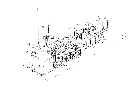
Fig. 1 is a perspective view, partly in ~ection, of a first
embodiment of the low NOX, integrated boiler-burner
cogeneration apparatus according to the present
invention, including a gas turbine and a forced
draft fan connected via an iniet duct to a multi-
nozzle burner (MNB) array located at an entrance to
the package boiler, and wherein one or more chill
tube assemblies are positioned in the furnace space
of the boiler;
Fig. 2 is a perspective view, partly in ~ection, of a
second embodiment of the low NOX, integrated boiler-
burner cogeneration apparatus, including a gas
turbine and a forced draft ~an connected via an
irllet duct to a multi-nozzle burner (MNB) array
located at an entrance to the package boiler, and
wherein one or more ;ntprn~l duct assemblies are
positioned in the furnace space of the boiler;
20 Fig. 3 is a perspective view, partly in section, of a third
' '1 ~ of the low NOX, integrated boiler-burner
cogeneration ~rri~ r~ , including a gas turbine and
a forced draft fan connected via an inlet duct to a
multi-nozzle burner (MNB) array located at an
entrance to the package boiler, and showing an
alternative aLLdll~ wherein one or more ln~Prn;~l
duct assemblies are positioned at upstream and
downstream locations (with reapect to a flow of
gase~ through the apparatus) in the furnace space of
the boiler;
Fig. 4 i8 a perspective view, partly in section, of a
fourth embodiment of the low NOX, integrated boiler-
burner cogeneration apparatus, including a gas
turbine and a forced draft fan connected via an
inlet duct to a multi-nozzle burner (MNB) array
located at an entrance to the package boiler,
wherein one or more chill tube assemblies and one or
Case 5524 21638~4
-- 7 --
more internal duct assemblies are positioned in the
furnace space of the boiler;
Fig. 5 is a perspective view, partly in section, of fifth
embodiment of the low NOx, integrated boiler-burner
cogeneration apparatus, including a gas turbine and
a forced draft fan connected via an inlet duct to a
multi-nozzle burner (MNB) array located at an
entrance to the package boiler, wherein one or more
chill tube assemblies and one-or more internal duct
assemblies are intf~r~r,or,e:ed among each other within
the furnace space of the boiler;
Fig. 6 is a clos~-up perspective view, partly in section,
of the ~urnace space of the low NOx, integrated
boiler-burner cogeneration apparatus illustrating
the placement of one or more chill tube assemblies
and one or more internal duct assemblies therein;
Fig. 7 is a close-up perspective view, partly in section,
of the furnace space of the low NOx, integrated
boiler-burner cogeneration apparatus illustrating
the placement of one or more chill tube assemblies
and one or more internal duct assemblies in the
furnace space, and wherein some of the one or more
chill tube assemblieg are positioned within the one
or more internal duct assemblies; and
25 Fig. 8 graphically shows an estimated combustion gas
temperature profile versus distance from the furnace
space inlet for a conventional burner-boiler
arrangement without furnace chill tube or int~rn;ll
duct assemblies, an optimum temperature profile for
NOx minimization, and a possible profile using the
present invention.
n~.... q~'RTPTION OF TE~ )nTMF~NT~q.
Referring to the drawings generally, wherein like
-r~ repre3ent the game or functionally similar elements
throughout the several drawings, and to Fig. 1 in particular,
a f irst embodiment of the invention is shown . A gas turbine-
Case 5524
` 21638~
-- 8 --
generator 2 having an outlet 4 conveys its turbine exhaust
gases (which are rich in oxygen) into a branch duct 6. Branch
duct 6 i8 fluidically connected to an inlet duct 12 for
providing the turbine exhaust gae (and combustion air as will
5 be described later) to a horizontally fired, factory assembled
package boiler generally designated 20 having a furnace space
8 for receiving flames from a multi-nozzle burner (MNB) array
6. MNB array 16 is located at an entrance to furnace space
18, preferably in an inlet windbox or plenum 14 connected to
inlet duct 12 of the package boiler 20. The MNB array 16
provides the fuel for combustion into the furnace space 18 of
package boiler 20. Package boiler 20 is of a known design
which includes a back wall 26 at which the combustion exhaust
gases moving htr17~nt~lly along furnace s~ace 18, turn through
180 and then move horizontally through a return run bank of
boiler tubes (not shown) which are fluidically connected
between upper and lower steam drums 22, 24, respectively. The
combustion exhaust gases subsequently pass through exhaust gas
flue 28 a~d leave the unit through a stack 30.
It will be noted that forced draft (FD) fan means 10 is
also provided, having an outlet connected to inlet duct 12, in
the preferred embodiments of the present invention. The
presence of FD fan mean3 10 in combination with the gas
turbine exhaust (which also provides additional combustion
air) allows the present invention to achieve higher loads on
the package boiler 20, independent of the loading of the gas
turbine-generator 2, or to even achieve full load on the
package boiler 20 with~ the gas turbine-generator 2 out of
service. As indicated earlier, industrial steam users want a
reliable steam supply regardless of whether or not the gas
turbine-generator 2 is in service. In addition, the gas
turbine-generator 2 operates most efficiently at 100~ loading
and package boiler 20 steam loads above the full load rating
on the gas turbine-generator 2 can be carried by the FD fan
means 10 and the additional fuel provided through the MNB
array 16.
Case 5524
` ~ 21~38~4
_ 9 _
Forced draft fan means 10 provides the necessary air for
combustion at desired flow rates and static pressures to
overcome all resi~tances in the system and exhaust the
combustion gases to/through the stack 30
It is understood that the present invention is not
limited to only the package boiler 20 shown Possible
applications readily visualized to those skilled in the art
would include any of the aforementioned "F" type boilers
including the PFI and PFT types, as well as the "Three Drum
Waste E~eat Boiler" commonly known in the industry as an "F0"
type boiler, or simply referred to as an "0" type boiler.
Accordingly, all such configurations are readily usable in the
combination of the present invention
In one aspect of the present invention, the hot or
tempered turbine exhaust gases from gas turbine-generator 2 is
combined via branch duct 6 with combustion air provided by
forced draft (FD) fan means 10 and fuel provided by MNB array
16 .
MNB array 16 preferably comprises a plurality of
vertically and horizontally spaced burner nozzles 32 which are
carried on the trailing edges of a plurality of air foils 42.
Bach burner nozzle 32 receives fuel ~rom a fuel line 34
~tl~n~li n~ into its respective air foil . The burner nozzles 32
are distributed in rows and columns on air foils 42 and are
provided so that the rows and columns of burner nozzles 32 are
spaced across the width and height of the entrance to furnace
space 18 to evenly distribute the fuel for combustion into the
furnace space 18. Preferably, a plurality of horizontally
extending and vertically spaced air foils 42 are provided,
extending across the entrance to the furnace space 18, each
air foil 42 carrying a hori20ntal row of burner nozzles 32
Alternatively, a plurality of vertically extending and
hor; 7-~nt:~11 y spaced air foils 42 may be provided, extending
across the entrance to the furnace space 18, each air foil 42
carrying a vertical column of burner nozzles 32
In another aspect of the pre~ent invention, the low Nx,
integrated boiler-burner apparatus of Fig. 1 is further
Case 5524
~, 2~ 638~
-- 10 --
outfitted with one or more vertically extending, horizontally
spaced chill tube sections or aæsemblies 36 within the furnace
space 18. Assemblies 36 are comprised of boiler tubes 38
which are fluidically connected between upper and lower steam
drums 22, 24 of package boiler 20 for immediately absorbing
heat from the burner flames. The number of the tubes 38, and
their diameter, spacing and materlals are selected using well-
known fluid flow ana heat transfer relationships to achieve a
desired water/steam side pressure drop and a desired heat
absorption from the flue gas to minimize NOy production due to
the combustion process. Preferably, each chill tube assembly
36 comprises a plurality of tubes 38 arranged in a single row
that extends parallel with the combustion exhaust gas flow
through the furnace space 18. One or more chill tube
assemblies 36 may be provided, arranged adjacent to each other
across the width of the furnace space 13. As shown in Fig. 1,
the one or more chill tube assemblies 36 may also be provided
- in one or more rows, with two or more chill tube assemblies 36
in each row. Fig. 1 shows four (4) such rows, with a pair of
chill tube as~ 36 in each row. Advantageously, the
rows and columns of burner nozzles 32 are positioned such that
their flames are centered between adjacent chill tube
assemblies 36, which are immediately downstream of the MN~3
array 16 . This ~ ; m; 70~ heat transfer between the combustion
exhaust gases and the chill tube assemblies 36, while
minimizing flame impingement on the tubes 38. This also has
the effect of quickly absorbing the heat from the combustion
exhaust gases resulting in a f lue gas temperature level below
which NOx formation is not a problem.
In yet another aspect of the invention, Fig. 2
illustrates a second embodiment of the present invention,
wherein one or more vertically l~rt~n~1; n~, laterally
perforated, and hor; 7mnti~11 y spaced internal duct assemblies
40 are positioned~within the furnace space 18. ~ere, exhaust
gases from gas turbine-generator 2 are combined via branch
duct 6 with the combustion air provided by FD fan means 10.
Both the turbine exhaust gases and combustion air flow through
~ Case 5524 2~ ~3844
the MN3 array 16 where they are mixed with fuel for combustion
in furnace space 18. Internal duct assemblies 40 are
connected to plenum 14 by means of 3taging duct 44 and plenum
46, to provide staging gases (turbine exhaust gases from gas
turbine-generator 2 and/or combustion air from fan means lO)
into the furnace space 18, beyond the MN~3 array 16. For this
purpose, sufficient fuel is provided through burner nozzles 32
to provided a fuel-rich mixture into the furnace space 18, any
rr-~in1n~ unburned fuel being burned i~n the vicinity of the
internal duct assemblies 40. Each duct assembly 40 is
provided with a plurality of apertures or slots 48 for
discharging the staging gases lnto the furnace space 18.
Suitable dampers and flow measurement devices (not shown)
would be provided in staging duct 44 and/or plenum 46 for
control and measurement. The staging gases discharged via
internal duct assemblies 40 minimize peak combustion
temperatures which will minimize I~0x formation, by restricting
- the combustion heat relea3e rate, while completing the final
combustion in the furnace space 18 downstream.
20 Advantageously, the duct assemblies 40 are positioned only a
portion of the distance into the furnace space 18 from its
entrance, approximately l/3 to 3/4 of the furnace depth. The
Z remaining furnace space 18 downstream is left substantially
~: free of obstructions to allow for final complete burnout of
25 any carbon monoxide before the combustion exhaust gas is
~uenched by the boiler generating bank tubes in a return
run(not shown), after the exhaust gases turn 180 at the back
wall 26 in the hor17r,nt~11y fired package boiler 20.
Certain package boiler 20 applications may re~uire
30 multiple staging introduction points in the furnace space 18
to achieve desired combustion temperature and heat release
Z profiles for efficient low ~0x operation. Accordingly, and as
shown in Fig. 3, in a third embodiment of the invention one or
more internal duct assemblies 40 may be provided, positioned
35 at upstream and downstream locations (with respect to a flow
of gases through the apparatus) within the furnace space 18 of
package boiler 20. A second, interconnecting staging duct 50
~ Case 5524 21~384~
-- 12 --
and a second plenum 52 would be provided for the downstream
internal duct assemblies 40. Again, suitable dampers and flow
mea3urement devices (not shown) would be provided for the
downstream internal duct aesemblies 40.
The present invention contemplates that a combination of
the chill tube assemblies 36 and internal duct assemblies 40
may be desirable. As shown in Fig. 4, a fourth embodiment of
the invention, one or more chill tube assemblies 36 and one or
more internal duct assemblies 40 can be positioned within the
furnace space 18. Three pairs of chill tube assemblies 36
arranged in three rows are shown, together with one pair of
internal duct assemblies 40 downstream of the ~ast row of
chill tube a6semblies 36. However, the invention is not
limited to this particular ar 'dll~ t, and any inter-
combination of these elements may be employed.
One such variation, by way of example and not limitation,
is shown in ~ig. 5, a fifth embodiment of the invention,
wherein one or more chill tube assemblies 36 and one or more
internal duct assemblies 40 are interspersed among each other
within the furnace space 18. Again, while two pairs of chill
tube assemblies 36 and two pairs of ; n~ ^n:: 1 duct assemblies
40 are shown, each type of assembly 36, 40 arranged in two
rows and arranged in alternating fashion, other arrangements
are possible and within the scope of the invention. The
different types of assemblies 36, 40 need not alternate; they
need not be equal in number; and one type of assembly can
precede the other as desired.
Fig. 6 is a close-up, perspective view, partly in
section, of the furnace space 18 of the low NOy, integrated
3 0 boiler-burner apparatus of the present invention illuetrating
the r~ of one or more chill tube assemblies 36 and one
or more ;n~l^n;~ duct assemblies 40 therein. It is preferred
that the chill tube assemblies 36 precede the internal duct
assemblies 40, in the direction of combustion exhaust gas flow
through the furnace space 18, and that they be in-line with
each other. In this way, combustion gas temperatures are
m;n;m;z~d and combugtion is then completed at the downstream
1,
~ Case 5524 21~ 3 8 ~ 4
-- 13 -
duct assemblies 40. While the means for discharging 3taging
gases into the furnace space 18 advantageously comprise the
apertures or slots 48 shown, other configurations can also be
used. For example, the apertures 48 can take the form of a
5 plurality of circular holes or perforations spaced in any type
of pattern and any place along the entire perimeter of walls
54 forming an ;nt~rn~1 air duct assembly 40.
Fig. 7 is another close-up perspective view, partly in
section, of the furnace space 18 of the low NOy, integrated
10 boiler-burner apparatus of the present invention illustrating
the placement of one or more chill tube assemblies 36 and one
or more int~rn~l duct assemblies 40 therein.` In this
particular configuration some of the one or more chill tube
assemblies 36 are located physically within some of the one or
15 more duct assemblies 40. Such an arrangement would be
particularly advantageous for cooling the assemblies 40 and/or
if space limitations in the furnace space 18 prohibit separate
locations of the chill tube assemblies 36 and the internal
duct assemblies 40. Again, apertures 48 can take the form of
20 slots, holes or other perforations spaced in any type of
pattern at any place along the perimeter of walls 54 forming
an internal duct assembly 40.
Fig. 8 graphically shows an estimated combustion gas
temperature profile versus distance from the furnace space 18
25 inlet for three separate situations. Upper gas temperature
profile curve 56 is the estimated variation in combustion gas
temperature when a conv~nti~nill burner and furnace
conf iguration would be employed. Note that the maximum
combustion ga3 temperature is approximately 2800F, which
3 0 would produce undesirable levels of NO,~ . Intermediate or
middle gas temperature curve 58 represents an estimated gas
temperature prof ile that is believed to be achievable with the
present invention. The maximum combustion gas temperature
shown thereon is approximately 2300F when the chill tube
35 assemblies 36 are employed. The second peak in the middle gas
temperature profile curve 58 is anticipated to occur when
additional air staging is provided by a downstream internal
I
Case 5524 21~384~
-- 14 --
air duct assembly 40 to complete combuetion, thereby
increasing the gas temperature. The lower gas temperature
profile curve 60 is a theoretical optimum curve that would be
deeirable, eince the peak combustion gas temperature of
5 approximately 1800F would be optimum from a NOX standpoint.
It will be appreciated that the arrangements of chill
tube assemblies 36 and internal duct assemblies 40 as æhown in
Figs. 6 and 7, particularly the aLLc~ nt of Fig. 7 wherein
some of the one or more chill tube assemblies 36 are located
10 physically within some of the one or more internal duct
assemblies 40, may be employed in any o~ the embodiments as
disclosed .
According to the present invention, NOX formation is
reduced to a minimum while the efficiency and completeness of
15 burning fuel in the furnace space 18 is maximized. A
particularly important aspect of the present invention is the
combination of the package boiler 20 with the MNB array 16
-= being compri~ed of a plurality of individual nozzlee 32,
rather than a conventional, single, circular-type burner. The
20 arrangement of individual nozzles 32 spaced inbetween the
chill tube assemblies 36 is important because it avoids the
deposition of eoot on the tubes 38. The arrangement also
allows the combustion process to proceed in an orderly,
controlled fashion as the gases proceed downstream of the MNB
25 array 16 through the furnace space 18. The preferred fuels
for the MNB array 16 include natural gas or fuel oils, and
other hydrocarbon fuels, and possibly powdered carbonaceous
fuels would be provided via the nozzles 32; the oxygen-rich
turbine exhaust gases and/or combustion air from fan means 10
30 is provided via inlet duct 12 and inlet plenum or windbox 14.
The chill tube assemblies 36 add a significant amount of
heating surface to the furnace space 18 and are thus able to
~3 reduce the ga~ temperatures down in the relatively short
distance to the desired temperature range, namely 1800F to
35 2300F, for NOX minimization.
P~ccordingly, while specif ic embodiments of the invention
have been shown and described in detail to illustrate the
. Caae 5524
. ~ 2163~44
-- 15 --
application of the principles of the invention, those skilled
in the art will appreciate that changes may be made in the
form of the invention covered by the following claims without
departing from such principles. For example, the present
5 invention may be applied to new construction involving factory
assembled package boilers, or to the replacement, repair or
modification af existing factory assembled package boilers.
Aa clearly exemplified by the numerous examples set forth
above, in some embodiment~ of the invention, certain features
10 of the invention may sometimes be used to advantage without a
corresponding use of the other features. Accordingly, all
such changes and ' ';l ' ~ properly faIl within the scope of
the following claim~.
.