Note: Descriptions are shown in the official language in which they were submitted.
216~259
-
BACKGROUNI) AND Ol~ CTS O~ Tl-TE TNVENTTON
T l~is invelllioll relates to a llew alld ilnpl-oved desi~ll associaled will~
tl~e ficll~l-icatioll an(l constr-llclioll of a lleedleless transrer systeln. Tn accordallce witll
tlle illventioll, tllroll~ll tlle llniglle desi~ll of tlle valve mecllanislll llsed ill accor(lallce
witll tlle invelltioll, tllere is acllieved a ~leedleless trallsfer system wl~el-eill olle is al)le
to trallsmit in one clirectioll a liq~lid n~edillln witllollt tlle necessity of lltilizill~ a
nee(lle, as is tlle COllllnOIl pl-aclice to date.
Witll tlle ~rowill~ collcerlls of translllittil~, eitller tllro~ advel-tel~ce,
accidellt, or otllel~ ~ise, a dea(lly or lli~llly conta~:iolls disease, I)e it AIDS, or
otl~erwise, tllere llas (levclol)c(l a ~rowi~ leed witllil1 tlle Ine(lical an(l llealtll care
pl-oressiolls of developill~ a Inealls by wllicll tlle llse of nee(lles ill coml)illatioll witll
a syrill~e is dinlillisl~e(l, as relaled to tlle mally tasks associated witll tlle Ireatlllellt Or
a patiellt. As is an(l as llas l)cell tlle comllloll practice in tlle me(lical colnlllllllity to
date, a syrin~e witll a lleedle attaclled tllereto llas l)een lltilized to remove fi-oln
stora~e colltaillers variolls Incdicilles, sollltiolls, and/or tlle like. By pllsllill~ tlle
nee(lle pOI-tiOIl tllereof Illl-oll~ll tlle elemellt sealin~ Ille contaillel (l~e it a cork-like
slll)sklllce or otllel~ise) alld tllen drawin~ o~lt illto tlle interior of said syrin~e tlle
vario~ls me(3icilles~ sollltiolls, and/or Ille like, an(J tlleri llpon witl~drawillg tlle needle
attaclled to said syrill~e fi-oln said contailler said needle attaclled to said syrin~e is
tllell il~serte(l illtO eitl~er allotller contaillerl t~ll)in~ system, alld/or tl~e likc, tllere
occ~lrs ~ series orlasks Illat expose a l~ealtll care pal1icipallt to accidelltal illjllly
fi-oln tlle ncedle ll~l~erellt ill said process is tlle risk orl~avill~ tl~e lleedle p~ chlre
tlle skin of tlle party calTyill~ ollt said process and tlle risk of contalnillatill~ said
palty witll a dea(lly or lli~llly del)ilita(ill~ disease and/or rorei~l slll~slallce llot
il~tencle(l for illtro(lllctioll illto tl~e l)o(ly of ll~e llealtll care participal~t.
216~2S9
It is in keepi~ itll tllis invelltioll to achieve tlle al)ility to translllit
me(licil,es, solutiolls, alld tl)e like, fiom olle envilolllllellt to anotller witllollt tlle
necessity of utilizillg a needle attaclled to a syrin~e so as to acl~ieve same and
thel el)y elilnillate tl~e collcerlls of accidental con~alninatioll of an individ~lal.
Altl~ou~l~ it is kllo~n in tlle prior art tllat sllcll risks.exist in tlle
utilizatioll Ora lleedle ill colnl)illatioll witll a syrin~e to acllieve tl~e admillisterill~ of
medicines, sollltiolls, al~cl tlle like, llone of tlle prior alt stnlct-lres address
tllelllselves to tlle speci~ic elnl)oclilllellt and tlle a(lvallta~es ~nd expediencies of tlle
presellt invelltioll.
Witl~ regar(l to said prior art WlliCIl addlesses itselfto tlle al~ove
concenls, it sl~ould ~)e noled tllat tlle rollowin~ patellts evidellce a~varelless of tlle
pl-ol)lelll seekin~ to l)e overcollle as well as relate to certaill stnlct~lres tllat seek lo
accomplisll s~me, llowever, said prior art neitller anticipates llor otllerwise teaclles
tlle l~resellt invelltioll More paltic-llarly, Ille pl-ior al-t referled to al)ove is as
follows: U.S. Patellt No.4,128,098, elltitled "Valved Sl)ike Trallsrer Device",
iss~led to Blooln e~ a/. oll Oecelnber 5, 1978; U.S. Patellt No.4,354,492, entillcd
"Medical Adlllillis(l-atioll Sct Witll Bacl~flow Clleck Valve", isslled to McPllee o
Octol)er 19,1982; U.S Patellt No.4,759,756, elltitlcd "Recollstitlltion Device",
issued to Forman et al. Oll J~lly 26,1988; U.S. I'atellt No. 4,936,841, elltitled "~luid
Colltailler", isslled lo Aoki et al on J-llle 26,1990; U.S. Patellt No.4,950,254,
entilled "Valve Mealls for ~nteral Tllerapy Adlllillistratioll Set", iss~led to Allderson
et al. on Au~llst 21,1990; U.S. Patellt No.5,125,415, elltilled "Syrill~e Tip Cap
wi(ll Self-Sealin~ l~ilter", iss~led to Bell oll Jlllle 30,1992; U S Patellt No
5,036,992, elltitlcd "Medicille Vial Cal) for Nee~leless Syl-il~e", isslled lo
Mo~lcllawar et al. on All~llst 6,1991; U.S Pa(el~t No 3,831,629, el~ti(le(l "Cl~cclc
` 21642~9
Valve", issued to Mackal ~t ~11 on Au~lst 27,1974; U.S. Patent No. 4,181,233,
enlilled "One-Way Valve stoppel", issued to Gouveia on Jamlaly I, 1980; U.S.
Patent No.3,904,059, entitled "Sterile Closure for Solutioll Bottles", issued to
Bellamy, Jr e~ al. on September 9,1975; and U S. Patent No. 5,202,093, entitled
"Sealing Cap w~ a One Way Valve Havin~ Semi-Cylindrical Valve Closure
Springs", issued to Cloyd on April 13,1993.
Tn keepin6 witl- tl-e invelltion, it is a specific object tllereof to create a
new and improved needleless transfer system tllat is siml)le in collstmctioll and
wl~ose use is facilitated by its desi~n.
It is anotllel objcct of 11~e presellt invelltioll to creale a new and
improved needleless transfer system wllerein tllere is overcolne tlle need and/or
necessity to utilize a nee(lle in conjllllctioll wi~ll a syrin~e to witlldraw, translllit,
and/or administer medicilles, sollltiolls, and/or tlle like, in COllj1111CtiOIl willl tlle care
and/or trealment of a patient.
It is anotller object oftlle present invelltioll to plovide a new and
improved needleless transfer system wllerein tllere is aclditiollally provided witllin
the needleless transfer system a mealls to filter any medi~lln passill6 tllere~llrougl
lt is anotller object of tl~e present invelltioll to l~rovide a new and
improved needleless transfer system wllerein multiple needleless transfer systems
can l)e utilized in COllj~lllCtiOlI wiill llle treatmellt of a sin~le illdividnal so as to allow
for tlle combillill6 of meclicines, sol~ltions, and/or tlle like, witllin tlle same
envirollment of treatmellt
~ t is anotller object of tlle presellt invelltioll to provide a new and
improved needleless trallsrer system wllerein tlle nOw of a Inedi~lm tlleretllrollgll can
be selectively deternlilled
'` ` 216g259
It is anotller object of tlle present invelltioll to provide a new and
iml)love(l needleless trallsrer systeln wl~erein Ille utilizatioll of tl~e needleless
transfer system will not contamillate tl~e envirollmellt from whicl~ a medium is
rellloved or into wllich a medillm is injected.
It is anotller object of tlle system to provide a simplified means of
transrenillg flllid media willlollt tl~e need for mllltiple and/or complex systems
and/or devices.
It is anotller object of tlle inventioll to provide a complete system in
and of itself llot reqlliring otller indepelldellt devices and/or compollellts whicl
ilizes present day standar(Js tllereby negating tlle need for re-toolin~ alld/or
cllan~ of standal-d devices in cunrellt use.
Tlle objects and advanta~es of tlle illventioll are set forth in part herein
and in part will be obviolls hererrom or may be leamed by practice of tlle invelltio
~lle same being realized and altailled by means oftlle instnllllelltalilies and
coml~ ations poillted O~lt In tlle appellded claims.
Tlle invelltioll consists in tlle novel parts constmctiolls arran~emellts
combillatiolls and improvemellts llerein sllown and described.
2i642~ !~
~,
BRTrl~ DESCRTPTTON Ol~ TITI~ DRAWINGS
I~IGURI~ 1 is tl~ree-dilllellsiollal perspective view of tlle valve
mecllanisln utilized in conj~ ctioll witll tlle needleless transfer system.
I~IGURE 2 is a paltial front view of tlle needleless transfer system
depictill6 tlle mecllallical coul)lill~ in accordance witll tlle inventioll of a syrin~e to
one end of tlle valve mecllallism depicted in l;IGURE 1.
~ I~URE 3 is a pal-tial cross-sectiollal view of tlle valve mecllanism
depicted in I~IGURE 1 taken alon~ line 3-3 wl~erein tl~e valve mecllanism is in its
closed posltlon ~nd ls n- mecllalllcal mterfit m accordallce wltl~ tlle inventioll with a
syrin~e sllown in parti~l cross section as well as additiollally depictin~ tlle valve
mecllallislll conple(l to tl~e molllll of a contailler.
I~GURE 4 is a partial cross-sectional view of tlle valve mecllanism
depicted in FIGURE I in mecllallical interfit witll an intravello~ls line as applicable
to its lltilization dllrill~ medical treatment.
~ IGURE 5 is a partial cross-secfiollal view of tlle valve meclla1lism
depicted in I~IGURE 3 in mecllallical interfit willl a syrin~e in accordance witll tlle
invelltioll wllerein tile valve mecllallislll is in an open posilion.
FIGURE 6 is a tllree-dimensiollal perspective view evidencin~ an
altemative embo(lilllellt to filter mellll)er 21 wllicll is car)able of bein~ utilized in
place of filter mcllll)er 2 ] ill tlle valve mecllallisln of tlle needleless trallsfer system
depicled i~ JGURES 3 4 and 5.
` 216425!~
'~
- DESCRIPTTON OF PREI~ERRED EMBODIMENT
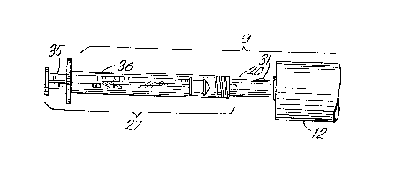
Reference is now llerein made to FTGURE 3 wllerein there is ill~lstrated
a cross-sectional view of valve mecllal1ism 10 collstnlclecl in accordal1ce witll the
invelllion as utilized in needleless transfer system 9. As depicted in FIG~E 2,
needleless transfer systenl 9 comprises valve mecl~anism 10 il1 combillatiol1 witl
syrill~e 27, syrill~e 27 bein~ an item well known in tlle prior art.
As ill~lstrated ill I~IGURE 3, valve mecl~allisll1 10 comr)rises l~ollow
enclosllre 11 wllicl1 defines a llollow cylindrical stnlctllre llavin~ a cylindrical wall
12 closed on botll ends by circular wall melnber 13 and circ~llar wall member 14 so
as to define an airti~llt cylindrical cavily. Stmctllrally affixed to tlle olller surrace of
cylindrical wall 12 is clamp mel11ber 15 and clamp mel11ber lG, clamp member 15
beill~ ronned so Illat tlle end Illereofl1ot aff;xed to cylindl-ical wall 12 is folmed to
define an~llar hook mell1ber 17. Sil11ilally~ clamp mell1ber 16 is fortned so tl-at tl)e
end tl-ereof not at~ixed to cylindrical wall 12 is formed to define an~llar hook
nelllber 18. In COl1jllllCtiOIl witll tlle above, it sllould l)e noted tllat as ill~lstrated in
~IGURE 1, valve mecllanisln 10 l1as eqllally spaced about tlle circllmferel1ce of
cylindrical wall 12 tllree clalnp melnbers, namely clalnp mel11ber 15, clamp Inember
16 and clamp melnber 45, all beln~ idel1tical in constmctioll so as to allow for Ille
stnlctllral arfixi~ of valve mecllallism 10 to eilller a contail1er as illustrated in
FIGURE 3, FIGURE 5 alld I~IGURE 6 of lhe drawill~s or to allow for tlle
stnlctllrally af~ixing of valve Inecl~allisln 10 to an intravellous port as illustrated in
I~IGURE 4 of tlle drawin~s. Clamp member 15, clamp mell1ber 16 and claml)
nlell1ber 45, alon~ willl an~llar llook melnbers 17, 18 alld 47 respectively, are
desi~ned so as to effect~late a detacllable mecllal~ical ~rip of valve mel11ber 10 onto
neck 23 of contail1er 24 as illllstrated in I~IGURES 3 an(l 5 or lo illtlaveno~ls port
- 216~2S9
nlelnl)er 46 of FIGURE 4 so as to allow for said valve mechal1isll1 10 to remai
sll-llctllrally arfixed tllereto ollce clalllped tllereon.
It sl~oul(l addi~iollally be noted ll~at it is witllin tlle scope of tllis
illventioll tllat ally means to acllieve tlle seleetive meellanieal affixing and removal of
valve mecllanism l O to and/or fi om a container suell as eontail1er- 24~ as illllstrated in
I~IGURES 3 and 5 or intravellc)lls port member 46 as illustrated in I~IGURE 4 is
contel1lplated llerein. More pal-ticlllarly in aceordanee witll tl1e above elamp
mel1ll)ers 15 16 and 45 ean be replaced by a serew-on-type or snap-ol1-type
stnlcl~ll-e capable of bein~ selectively attaclled to llle neck of contail1er 24 and/or
intravellolls port melnber 46 sllcll stmctures bein~ well knowll in ~lle prior alt.
As rurtller ill1lstrated in l~IGURE 3 tllere is protnldil1g fi-om cireular
wall melllber 13 at tlle eenter tllereof and at rigllt angles to circlllar wall member 13
llollow spike meml)er 19 llollow spike meml~er 19 folming an airtigllt seal wi~ll
cylindrical wall member 13 ancl defillill~ at its spiked end a strllctllre tllat is capable
UpOll Ille applicalioll of force parallel to tlle axis of llollow spike melnl~er 19 to
pel1etrale tllrougl1 Inaterial tllat is utilized as a stopper and/or otller sealant nont1ally
lltilized to seal tl1e neck of a con~ail1er intravellolls port mel11ber of an intravel1o1ls
systenl or tlle like. Protnldin~ from cylindrical wall member 14 at tlle center thereof
and at ri~llt an~les to circ1llar wall melllber 14 is llollow eylindlical neck mell1ber 20
wllicll is stmctllrally affixed at one of its ends in an airti~l1t mal1l1er to circular wall
Inelml)er 14. Tlle oll~er en(l of l ollow cylindl-ical neck mell1ber 20 derines an
exlerior tllreaclil1g 25 capable of nlecllal1ical inlerfit in an airti61lt fasl1ion witl
interior tl1reading 26 appearing on cylin(il ical sllart member 36 of syrin~e 27 sllcl1
tl)at 1lpon ll~e insertioll of tlle lil) n1el11ber 34 of syrin~e 27 as illllstrated in T~IGURE
3 illtO neck n1ember 20 ancl nllc)ll tlle clockwise rotalioll of said syrill~e 27 tllere
21642Sg
occllrs a mecllanical interlit between syringe 27 and neck mel11l)er 20 tllat is air tigllt
and leak proof due to tlle mecllallical interfit of il~terior tllrea(~illg 26 of syrtn~e 27
witll tlle exterior tllreading 25 of neck mcmber 20.
- Contail1ed willlill l1ollow enclosule 11 and positioned adjacent to
cylindrical wall 12 is filter member 21 wllicl1 defines a si)ape cylindrical in fonn and
coml)atible witl~ at of tlle interior cavity defined by llle interior surfaces of
cylilldrical wall 12, circlllarwall member 13 al)d circlllar wall lnember 14. It sllould
be l-oted tllat filter metnber 21 is of a stmctllral comr)osiliol1 s-lcl1 lllat it is capable
of beil1g colnpressed Ill~oll llle al~plication of a force alol1~ its axial len~tll as well as
to allow for tlle passa~e tlllo~lgll its stnlcture of a ligllid me(lillln wllile ~llering
same. Allllou~l~ tllis invel1tiol) sllould not be consi(lered limited to tlle followin~, it
is envisiol1ed tllat in tl)e r)rererre(l embodimel1t llereor, filter melnl)er 21 call be
conslmcted froln any one oFtlle following materials, to wil, Nitrocell~llose,
Cell~llose Ace~ate, Nylon, Polys~llfane, Porolls Plastic, or P~lre Poly.
In filrtller keel)ing witll tlle invelltioll, alld as depicted ill I~IGURE 3,
tl~ere is structurally affixed to filler member 21, washer mel)1ber 28. In keeping witl
tl~e illvenliol1~ wasller Ineml3er 28 can be fabricated fi-om any olle of a n~ll11ber of
coml)osiliol1s of matel-ial, tlle l)asic cllaracteristics tllereof l)ein~ sllcll lllat wasller
nlelllber 28 is cal)aI)le of sealill~ orf l3y way of all air tigllt all(l/or liquid ti~llt seal tlle
interior of llollow enclosllre 1 1 fi-om llle passage of al~y lig-lid introdllced into necl~
Inelllber 20 As IOI1~ as rilter member 21 is not conll)l-esse(l l)y mecllal1ic~1 pressllre
directed parallel to ll~e axis of filler mell)ber 21 al)d a~ainst wasller member 28 so as
to cause wasller nlel))l~er 28 to lnove away frol)1 cylilldrical wall member 14, filter
melnl)er 21 in its llncol)1l)resse(l state l~rovi(les sllfficiellt l~ressllre against wasller
lnell1I)er 28 so as to force wasller melnl)er 28 lll3 a~iaillst cylilldl-ical wall lnelnl3er 14
~ 216~2~9
so as to provide an air and/or li(l-lid tigllt seal at tllat locatiol1.
I'rotnldil1~ fi-oln tl~e sllrface of wasller mell1ber 28 and stlllct~lMlly
a~;xed thereto is sllart member 22. Slla~t member 22 is cylindrical in sllape and
stnlcturally affixed to wasl~er mel1lber 28 at tl-e cellter of wasller member 28. Sl1af~
member 22 protmdes into the cylindrical interior openil1~ 29 of neck member 20.
Stnlcturally affixed to sllalt melnl)er 22 and axily aligned witll sllaft member 22 is
indica~or sl1art 30. In(lica~or slla~t 30 is color coded so as to indicate tllrollgl1
will(low element 31 rornled willlin neck member 20 ll~e pOSitiOI1il1g of shalt member
22. As indicated in l~IGURE 3 indicator sllaft 30 llas two separate and distinct
colored portions one colored poltion tllereof in accordance willl t11e invel1tiol1 l)eing
indicated by a red colored s~lrface 32 and tlle remail1illg portion of indicator slla~ 30
havil1g a greell colored surFace 33.
As indicated in I~IGURE 3 wllen wasller melnber 28 is in ils sealed
pOSitiOll adjacellt to circlllar wall member 14 no liq~lid is allowed to pass tllrougl
valve mecl1al1ism 10 and red colored sllrface 32 of indicator sllaft 30 is able to be
observed tllrougll window elemellt 31. Upon observing a red indicatiol1 tllroll~ll
window element 31 olle is able to determille Illat valve mecllanisln 10 is in a closed
and tll~ls nol1-operative pOSiliOIl. It sllollld be noted tllat Will(30W elemel1t 31 can be
fabricated frol11 any one of a nlll11ber of materials be it glass cleal- plastic or ~he
like and is affixed in all air tigllt Inalll1er willlill tlle opellil16 fom1ed in neck member
20 desi~led to receive willdow elemellt 31 s~lcll tl-at lllere is providecl a mealls
readily available to detenl1il1e wl-ell valve mecl1allisln 10 is in an open pOSitiOI1 or a
closed pOSitiOIl. As illllstrated in FrGURE 3 valve mecl~anisln 10 is in a closed
pOSitiOIl and is evidenced by ~lle fact tllat red colored sllrface 32 of indicator sllaft
30 is positiolled directly llnder window elelnel1t 31. Upon rererrill~ to FIGURE 5
-10-
,, , 216g259
valve Inecllallisln 10 is in an open pOSitiOIl as evidenced by tlle fact tllat ~reen
colore(l SUIrace 33 of indicator sllaft 30 is positioned ull(iel window elelnel~t 31
As indicated in i lGURE 5, llpOIl tlle insertioll of tip meml)er 34 of
syrill~e 27 illto lleck melnber 20, tip member 34 of said syrin~e comes into pllysical
contact wi~ll indicator sllaft 30 Upon tl~e rotatiol~al tllreadin~ of said syrin~e 27 in
COlljllllCtiOIl witll neck member 20, tip member 34 of syrin~e 27 advances inward in
axial ali~lment witll shart meml)er 22 As il~dicated in I~IGURE 5, llpOII s~rill~e 27
beil~ mecllal1ically collpled to neck meml)er 20 I)y tl-e rotational tllreadill~ and
mecllallical interco~ll)lill~ of illterior tllreadin~ 26 of syrin~e 27 witl~ exterior
Illleadin~ 25 of neck melllber 20, syrill~e 27 l~ecomes mecllallically attached to
valve mecllallislll 10 in accordance witll tlle implelnelltatioll of tlle needleless
transrer system in an air tiL~llt/liquid ti~llt couplill~
IJpoll tl~e initial co~lplin~ of syrin~e 27 to neck member 20, tip mell1ber
34 is not initially in direct mecllanical contact witll indicator shaJt 30 as depicted in
I~IGURE 3 As depicte(l in I~IGURE 3, syrin~e 27 is in initial mecllallical co~lplin~
witll neck member 20 s~lcll tl)at wasller member 28 is Inecllallically positioned
pllysically adjacellt to circlllar wall melllber 13, tllereby effectively CIOSillg off valve
mecllallisln 10.
Upoll tlle filrlller rotational movelllellt of syrin~e 27 so as to callse tlle
filrtller intercolll)lill~ of illlel-ior lllreadill~ 26 willl exterior tllreadill~ 25~ as depicted
in l~lGURE 5, tip meJnbel- 3~1 is callsed to axially move ~owards wasller member 28
so as to l)e mecllallically forced llp a~ainst indicator sllan 30 Upon tlle filrtller
rotation of syrill~e 27 as refen-e(l to above, tllel-e occllrs tlle filrtller axial movel11ellt
of tip Inellll)er 34 towal-ds wasl)er Inelnl)er 28 sllcll tllat in(lic;ltor sllaft 30, sllan
Inember 22 and wasller nlelnl)er 28 are all foa-ced to mecllallically move sl~cll tllal
~_ 21642~9
wasller member 28 is forced away from tl~e interior sllrface of wall meml)er 13 as
indic~led in l;IGURE 5. /~,s a result filter meml)er 21 is compressed and tl~lls valve
n1ecl~al1isl11 10 is in its open pOSitiOll so as to allow for tlle flow of a liqnid as
illustrated in FIGURE 5. As illustrated in ~IGURE 5 a liquid is able to llOw eitller
rronl syrin~e 27 tllroll~ll neck n~el11bel 20 tllroll~ll l1ollow enclosllre l l via filter
member 21 and tllrou~l1 llollow spike meml~er 19 into tlle interior of contail1er 24 or
in tl1e alten1ative a li(lllid can l~e witlldrawn from tlle interior of container 24 by
llavill~ said liq-lid llOw tlllo~ ollow spike melnl)er 19 Illroll~l1 filer meml)er 21
tllrou~ll hollow enclos1ll-e 11 tl1ro~ e ]lollow interior of neck member 20 and
into tl1e interior of syril1~e 27.
Tlle directioll of llow of a ligllid in accordal1ce witll tlle al~ove and as
referred to witll re~ard to ~IGURE 5 is detennil1ed l)y wlletller or not syrin~e 27 as
illllstrated in l~IGURE 2 eilller llas its pllll1~er 35 initially positioned inserted all tlle
way willlill tlle sllart mellll~er 36 of syrin~e 27 sllcll tllat llpon Ille movelnent of
plull~er 35 in a direcliol1 so as to draw itself ollt firom witllin sllart mell1l)er 36 of
syri~ e 27 a vacnuln is created witl1il1 syrin~e 27 so as to in effect s~lck out a liquid
firol11 contail1er 24 as a reslllt tl~ereof or in tlle altemative llpOIl llavin~ syrin~e 27
llave its pl~ er 35 witllcllawll fionl sllart meml)er 36 of syrill~e 27 and tllere bein~
conlailled witllill sllart meml)er 36 a lig1lid and llpOIl tllen tllreading syrin~e 2~ onto
neck meml)er 20 as in(licatc(l in T~IGURE 5 sllcll tllat wasller meml~er 28 is forced
illt-o t11e open position of valve mecllallisln 10 tllere is tllen created tlle ability to
inject fioln syrin~e 2~ into conlailler 24 a liqllid in accordance witll tlle illventioll all
of tlle al~ove not reqllirill~ tlle utilizatioll of a needle.
In keel)in~ wi~ e invelltioll it sl~ollkl also l)e noted tllat as ill~lstrated
in ~IGURE 4 valve mecl~allislll 10 cal1 I)e n~ilized in COI1jUI1CtiOI1 witll an
.~_ 2164259
inlravellous drip system as tllereil~ lstrated. 1n utilizil1g valve mechal1islll 10 in
COllj~lllCtiOIl witll an intravel1olls drip system clamp member 15 16 and 45 snap
onto tl~e exterior of intravellolls port melt1ber 46 as illustrated in I~IGURE 4 after
llollow spike member 19 llas been forced tllrollgll intravellolls port member 46.
Furtllennore it sllould also be noted that in keeping witll tlle invention
fillel- member 21 as illustrated in FIGURES 3 4 and 5 can be replaced Witll an
altenlate filter mecl~anislll 37 as illllstrated in I~IGURE 6.
More particlllarly filter mecllallisl1l 37 comprises a llollow cylindrical
wall member 40 llaving circlllar end member 38 and circular end member 39 as
tllereill depicled wall meltlber 90 of filler mecllallislll 37 1l3villg fomled tllereill and
mnllillg from said circular en(i members 38 and 39 a series of slits 41 sllcll that ~Ipon
llle compression of filtcr mecllallism 37 by callsing circlllar end melllber 39 to move
towards circular end member 38 tlle slit openillgs 41 fonned ~llrollgll wall meltlber
40 of filter member 37 palt and otllerwise ol en llp widcr ~llan is tlle case in filter
mecllallism 37 s ullcoll-pressed state so as to allow for tlle free nOw of ligllid from
eilller tlle interior of filter nlecllallism 37 to tlle exterior tllereof or vice versa all in
keepillg willl tlle invelltioll.
1n filr~ller keepillg willl llle invenlioll fil~er mecllal-ism 37 in
accordance wi~ll llle alten1ative embodiment tllereof as llereinabove set fortll is of
sucll a desi~ll an(l constnlclioll so as to be readily snl)s~ tcd for filter melnbcr 21.
~n accordance tllerewitll filter mecllanism 37 llpOIl its lltilization in valve
mecllanisln 10 as would be evident UpOIl viewin~ oF1~1GURE 5 llas llollow spike
member 19 stmcturally affixed to circlllar end member 38 at opellil1~ 42 wllile
circlllar end member 39 oF filler Inecllallislll 37 is stnlctllrally affixed to wasller
melllber 28.
-13-
~ 1 1 6 4 2 S g
l~or all practical purposes, filter mecllanisln 37 is desi~ned so as to
provide an alternalive embodimellt to filter member 21 of valve mecllallisl11 1~ as
depicted in FIGURES 3, 4 and 5 wllerein filter mecl1anism 37 is basically
substitllted for filter member 21. It sl~ould filrtl1er be noted that contail1ed within the
inlerior of filtering mecl1al~ism 3~ as depicted in FIGUI~E 6 is a col1lpressiol1 of
filterin~ material 43 capable of removin~ impurities from a liquid in a similar fasl1ion
to that whicll is accomplisl1e(1 by filter member 21 as depicted in I~IGURI~S 3, 4 and
5. As hereil1 preferably embodie(l, filterin~ material 43 can be any one of ~l1e
followin~ compositions of material, to wit, Nitrocellulose, ~lass paper or any
malerial currel1tly llsed in filtraliol1 of liguids to tlle specified pOlOllS re9llirelllelltS
needed for tlle particular use.
Jt will be ul1derstood tllat tlle fore~oinL~ ~eneral descripliol1 and tlle
followin~ detailed description as well are exemplary an(l explallatory of the
invel1tiol1~ but are not restrictive tllereof.
Tlle accompallyil1~ drawin~s referred to hereill and constit1ltill~ a part
llereof, are illustrative of tlle invelltion but not restrictive lllereor, and, to~e~ller witl
e descril)tiol1, serve lo explail1 tlle prillcil)les of tlle invel1lio
-1 4-