Note: Descriptions are shown in the official language in which they were submitted.
2164773
W~ll~lOCK AND STARTER MILL
BACKGROUND OF THE INVENTION
When an oil well has been drilled, or partially drilled, and cased, it is
sometimes desired to open a window through the side of the casing to permit drilling
S of a deviated or side-tracked branch of the well disposed at a ~s~llial angle with
respect to the ~ .nt portion of the original wellbore.
A common way of so opening a window is to set a whipstock in the original
wellbore. The whipstock has a generally concave radially inner side, face side, or
trough which is angled or tapered downwardly and radially inwardly with respect to
10 an adjacent side of the well wall, typically a casing wall. A starter mill appal~lus,
including an inwardly and downwardly tapered pilot portion below a milling portion,
is lowered relative to the whipstock while also being rotated. The whipstock is
furnished with a pilot lug near the top of its concave tapered inner side which engages
the tapered pilot portion of the starter mill as it is lowered, directing and forcing the
15 mill into the side wall of the casing facing the whipstock trough to effect penetration
of the casing and facilitate cutting of the window. Thus, the starter mill forms a
small lateral opening through the casing, or at least mills into the casing sufficiently
to form a ~ub~ lial upwardly facing shoulder in the casing. Then the starter mill
a~palalus is withdrawn and the milled part of the casing is elongated a window mill,
20 which will form a sufficiently long window in the casing to serve as the upstream end
of the side-tracked well branch when drilled th~lt;rlulll in a manner well known in the
art.
A common problem with known apparatus of this type is that the starter mill
inevitably mills into the whipstock to a greater or lesser extent as well as the casing,
2:~64773
thereby d~m~ging the whipstock, possibly to the extent that it is thereafter impossible
to mill a window. This problem results from the fact that it is difficult, if not
impossible to determine precisely at what point the starter mill has milled a sufficient
amount of the casing to permit the starter mill to be removed from the well and
S replaced with a window mill in order to complete milling of the window. Normally,
milling is commenced with the starter mill and continued for a measurable dowllw;~
distance which would be sufficient to mill the pilot lug from the whipstock and start
the window. When milling with conventional coupled tubulars, such as drill pipe, at
excee~lingly great depths in a well, it is difficult to accurately measure the relatively
10 short distances required to mill the pilot lug from the whipstock because of the
elongation or stretch in the tubulars due to the tubulars' own weight. In the above
instance, the degree of accuracy of measurement may range in feet rather than inches
depending upon the depth of the operation. The problem of accuracy of measurement
is significantly m~gni~1ed when milling operations are conducted using downhole mud
15 motors suspended from the bottom of coiled tubing strings. The degree of accuracy
of measurement under the latter operations, can easily range between ten and twenty
feet depending upon the depths of the operations.
The ability to start a window may be further exacerbated by rotational and
longitudinal frictional wear to the starter mill pilot and/or the whipstock pilot lug. If
20 the starter mill pilot becomes worn to a smaller outside diameter and/or if the height
of the whipstock pilot lug is decreased due to wear as the respective items engage and
co-relate with one another to effect the starting of the window, resulting or final
dimensions of the respective items may be such, at the point of pilot lug mill-off, that
the casing wall is not penetrated or a sufficient shoulder is not created in the casing
- - 216~77~
wall to f~cilit~te subsequent proper milling of the window with the window mill.
This problem is most prevalent in applications involving through-tubing
window milling, where a smaller ~i~m~ter tubular is positioned within the well above
a larger size casing in which a window is to be milled. Since the outside ~i~mPtPrs
5 of the anchors, whipstocks, mills and other tools employed in milling the casing
window must be of a size small enough to pass through the smaller tubular and
operate to cause milling of a window in the larger casing, the starter mill must be
equipped with milling blades having less depth and pilot noses having smaller
diameters as well as whips~ocks being furnished with thinner pilot lugs than are used
10 on conventional full bore window milling operations. Thus, excess or slight wear, in
some cases, cannot be tolerated without subsequent failure to start the window.
Another problem which exists with known apparatus, again with particular
respect to through-tubing applications, stem from the lack of support of the back side
(opposite the tapered concave face) of the whipstock by the adjacent casing wall.
15 Since through-tubing whipstocks must be of a much smaller diameter than the casing
in which they are set, they must be diagonally angled within the larger casing when
set so as to position the top back-side against the inside of the casing opposite the side
in which the window is to be milled while the bottom face-side is positioned against
the casing adjacent the side in which the window is to be milled. Thus situated in an
20 unsupported position along its full back-side by the casing, the whipstock is
susceptible to flexing or bending when contacted by downward forces exerted upon
it by the milling tools. Should this occur, flexing of the whipstock would result in
the starter mill not being forced into the casing wall by contact of the starter mill pilot
nose with the whipstock pilot lug.
- - 216~773
With respect to full bore window milling applications, although state of the art
whipslocks are e~uipped with hinges below the tapered concave troughs to enable the
back side of the whip~lock to lean against and contact the side of the casing opposite
the window to be cut at their top ends, the angle between the back-side of the
5 whip~lock and the ~ ~nt casing is so small and the un~up~lled standoff so slight,
relative to the depth of the starter mill blades, that slight flexing of the wl~ip~lock
does not usually effect successful starting of the window. The same is usually true
with regard to wear of the window mill pilot nose and the whipstock pilot lug owing
to the greater depth of the starter mill blades in full bore window milling operations.
-
216~77~
SUMMARY OF THE INVENTION
The present invention involves several ~pect~, each of which can address one
or more of the above problems independently, but which, in p~el~lled embo(limPnts,
act in colllbinaLion to provide particularly effective solutions.
In one aspect of the invention, the outer or back side of whipstock has a
vertically elongated upper portion which is angularly disposed with respect to a lower
portion thereof. Thus, the upper portion may abut the adjacent well wall side along
its full length when the lower portion is inclinçd downwardly and inwardly with
respect to that same well wall side, at least some such inclination being neces~it~tP~
by the fact that the whipstock must be able to pivot with respect to the supporting
assembly. In addition, a pilot lug in provided projecting generally radially inwardly
from the inner side of the whipslock adjacent the upper end. This pilot lug has a
generally radially inwardly facing lug surface which is disposed at a downward and
inward angle with respect to the aforementioned side of the well wall. Furthermore,
the vertical length of at least a primary portion of this lug surface is less than the
vertical length of the upper portion of the outer or back side of the whipstock.The relatively large bearing surface thus provided between the whipstock and
the ~dj~cent side of the well wall, after seffing of the whipstock, serves to resist
flexing of the whipslock when it has been engaged by the starter mill apparatus.Furthermore, because the pilot lug projects inwardly from the adjacent portion of the
inner side or trough of the whipstock and provides an angular pilot mill surface, said
pilot mill surface, upon engagement by the mill pilot, directs the mill away from said
whipstock, allowing said mill to ade~uately mill the opposite side of the casing wall
before it directly engages and begins to mill into the main body of the whipstock.
- 216~773
- 6 -
The milling operation is enhanced or accelerated if the angle between the pilot mill
surface and the well wall is greater than the angle between the whipstock trough and
the well wall. Although the pilot lug itself will be at least partially milled away, the
whip~lock Ie-llains in proper form to guide a window mill after use of the starter mill.
The starter mill ap~tus includes a nose piece disposed below the bit, mill
cutter or milling blades, said nose piece being independe~tly rotatable relative to the
cutter or blades. The nose piece has an outside diameter at its upper and largest end
that is greater than the distance between the lower part of the pilot lug and the side
of the casing wall to be milled. Thus, after the mill apl)aldlus has advanced a certain
distance downwardly with respect to the whipstock, the nose piece will become
lodged or wedged between the bottom of the pilot lug and the side of the casing in
which the window is being milled, thereby preventing further downward movement
of the milling apparatus. The dimensions are chosen so that this will only occur after
the starter mill has milled a sufficient amount of the casing away, and has milled a
portion of the pilot lug, but has not milled into the whipstock proper. Thus, this
arrangement further prevents damage to the whipstock proper.
Additionally, when the starter mill nosepiece becomes lodged or wedged
between the whipstock and the casing wall, no further downward movement of the
starter mill occurs relative to the casing and whipstock, and since the cutter and its
milling blades rotate independently relative to the starter mill nose piece, the cessation
of downward movement of the starter mill results in no further milling of the casing
wall and pilot lug. In addition, the bearing assembly of the starter mill pilot nose
permits the starter mill blades or milling cutters to rotate, relatively free of friction,
with respect to the lodged or wedged pilot nose. The above resultant actions cause
21~773
a noticeable reduction in torque re~luilelllents to rotate the starter mill which are
observable by a drilling opel~tor at the surface of the well. With regard to
conventional rotary drilling, the torque reduction is observable from state of the art
instrllmPnt~tion. With coiled tubing drilling applications employing a downhole fluid
5 driven mud motor, torque reductions are observable by a reduction in the required
fluid pressure to operate the motor. The noticeable occurrences of the above actions
provide ~mmi~t~k~hle signals to the drilling operator: that the starter mill has
successfully completed its function of starting the window in the casing wall and
removing a portion of the starter lug from the whipstock; and that the starter mill may
10 be removed from the well and replaced with a window mill which will be run into the
well to engage the milled shoulders in the casing wall and pilot lug of the whipstock
to complete the milling of the window.
Various objects, features and advantages of the invention have been suggested
by the foregoing, and others will be made apparellt by the following detailed
15 description, the drawings, and the claims.
7 3
- 8 -
Brief Descliplion of the Drawings
Fig. 1 is a side elevational view of prior art starter mill a~alatus, whip~lock
and anchor in a first position.
Fig. 2 is a view similar to that of Fig. 1 showing the appaldlus in a second
S position.
Fig. 3 is a longitudinal quarter-sectional view of a starter mill assembly
according to the present invention.
Fig. 4 is a transverse cross-sectional view taken along the line 4-4 of Fig. 3.
Fig. S is a pel~pe~ e view of a through-tubing type wllipslock in accord with
10 the present invention.
Fig. 6 is a side elevational view of the starter mill assembly and whipstock in
use in a first position.
Fig. 7 is an enlarged detail view of the appaldtus of Fig. 6 in a second
position.
~164773
Detailed Descliplion
Figs. 1 and 2 more specifically illustrate an example of a prior art appal~lus
of a type which can be improved by the present invention, as well as some of the
problems associated with that art a~p~alus. The appa~ s is illustrated as it would
5 appear in a vertical well casing 10 for convenience, terms such as "uppern, "lower"
and "vertical" are used herein with reference to such typical orientation, and are not
to be construed in a limiting sense.
The appal~lus includes a whi~lock 12 having its lower end pivotal connected
to an anchor assembly 14 therebelow. The anchor assembly can be of any suitable
10 type, as well known in the art, and will not be described in detail. It is merely noted
that the anchor assembly 14 includes slips 16 which can be urged radially outwardly
to grip the casing 10 and fix or anchor the assembly 14, both longitu~in~lly and
rotationally, with respect thereto. Slips 16 can be either permanently positioned or
selectively retractable so that the whip~lock and anchor assembly can be retrieved
15 from the well.
The whipstock 12 has an inner side 18 an outer side 20. Inner side 18 defines
a concave trough, deepest at its upper end and shallowest at its lower end, with a
tapered width (see Fig. 5 which is similar, in this respect, to the prior art) varying
from a wide upper end to relatively narrow lower end. As shown in Fig. 1, inner 18
20 and outer 20 sides converge, to a narrower upper end, from a relatively wide lower
end. Sides 18 and 20 are arranged asymmetrically. More specifically, it can be seen
that, when the apparatus is in the starting position of Fig. 1, the outer side 20 lies
generally parallel to a closely adjacent side 22 of the well wall, which in this case is
defined by the casing 10, whereas the inner or concave face 18 is disposed at a
21~ 177~
- 10-
significant angle with respect to side 22.
The apparatus also includes a starter mill assembly including the cutter or bit
proper 24, a connecting member 26 carrying the bit 24 and connecting it to a
suitable work string (not shown) for rotating it, and a pilot or nose 28 depending
5 dowl,wardly from the bit 24.
Near its upper end, whiy~lock 12 has a small rectangular lug 30 welded or
otherwise affixed near the top of its inner side 18 and projecting inwardly thererrolll.
Lug 30 is initially connected to the bottom of nose 28 by a shear pin arrangement 32,
as is well known in the art.
After the whipstock 12 is set, a predetermined amount of tensile force applied
to the workstring, from the surface of the well, breaks the shear pin, releasing the
starter mill from the whipstock. The starter mill assembly 24, 26, 28 may then be
rotated and moved downwardly with respect to the whi~slock 12. As the nose 28
moves down, the whipstock is caused to pivot; specifically its upper end moves
15 radially oulw~rdly to a position shown in Fig. 2 wherein the upper end abuts the side
22 of the casing 10. In essence, only point contact is provided between outer side 20
and wall side 22, and that point contact is at the upper end of the whipstock 12,
which is the thinnest part.
Lug 30 will direct the assembly 24, 26, 28 away from the whipstock 12 as the
20 tapered nose engages the lug 30 and is lowered relative thereto. Lug 30 serves to
continue to urge the starter mill assembly 24, 26, 28 closer and closer to the side 34
of the casing 10 diametrically opposite side 22. After starting of the window on side
34 of the casing 10 by inner-engagement of nose 28 with lug 30, the bit 24 begins to
engage the lug 30. Continued downward milling will cause the lug 30 to be milled
216~773
1 1 -
from the whipslock, and if such milling is not discontinued immediately thereafter,
the bit 24 will continue to mill both casing and whipslock, as shown in Fig. 2, until
the nose 28 wedges between the casing wall 10 and the troughed inner side 18 of the
whipslock 12 causing a step 36 below said trough of the whipstock 12. The step 36
may thereafter be engaged by the window mill (which replaces the starter mill for
continued milling of the window) and follow or track step 36 to mill into the body of
the whipstock 12 rather than the casing 10. Further, because of the aforementioned
point contact between surfaces 20 and 22, the whipstock 12 may flex under the
downward force of the bit 24, exacerbating the extent to which the whipstock is
damaged at step 36 by bit 24.
As Figs. 1 and 2 show, these problems can occur even where the whipstock
12 is a full bore casing whipstock, i.e., a whipstock which can be run into a casing
string which is free and clear of any substantial restrictions. In the case of
through-tubing whipstocks, the aforementioned problems are exacerbated because, in
order to enable the whipstock to pass through a tubing string set within the casing,
the whiy~lock must be of a much smaller outside diameter than the inside diameter
of the casing in which it is set, and it must be configured so that its outer or back
side is disposed at a significant angle with respect to the adjacent side of the well wall
after its setting within the casing.
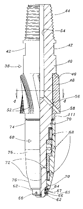
Turning now to Figs, 3-7 there is shown an appa~ s according to the present
invention which addresses the above described problems. Figs. 3 and 4 best show
the details of the exemplary starter mill assembly 38. Assembly 38 comprises a
central longitudinally extending mandrel 40, the upper part of which is exposed and
defines make-up and break-out flats 42 and a pin connector 44 for making the
- 2161773
assembly 38 up into a suitable workstring of a type well known in the art, and
diagrammatically indicated at 46 in Fig. 6. More specifically, when coiled tubing 47
is employed as the ~o,k~l.;ng, the starter mill assembly 38 is connected to a
downhole mud motor 45 which imparts torque to the starter mill assembly 38
5 following the pres~u~ized pumping of fluid through motor 45 and coiled tubing 47
extending upwardly therefrolll.
Somewhat below the flats 42, the mandrel 40 has its diameter reduced to form
a downwardly facing shoulder 46. The milling tool or bit 48 is emplaced in
surrounding relation to this reduced diameter portion of the mandrel 40 with its upper
10 end in abutment with shoulder 46, to prevent upper movement of the bit 48. As
shown in Fig. 4, splines 50 interconnect the mandrel 40 and bit 48 to prevent relative
rotation therebetween. The bit 48 includes a number of blades 52 which extend
radially outwardly from a central annulus of the bit 48. Blades 52 also spiral
longitu~in?lly and circumferentially about the central annulus of bit 48 so as to
15 maintain continuous blade contact with the concave face 88 (described below) of the
whipstock 12 as the starter mill assembly 38 is rotated.
The upper portion of the mandrel 40 has a central bore 54 extending
downwardly thereinto and termin~ting at an intersection with one or more smaller
bores 56 extending angularly downwardly and radially outwardly through the mandrel
20 40, and each aligned with a similar angled bore 58 opening out through the bit 48
adjacent an outer lower edge thereof. A suitable fluid may be circulated through this
system to cool the bit blades 52 and wash away debris, and it will be understood that
splines 50 maintain proper alignment of matching pairs of bores 56 and 58.
The bit 48 is retained on the mandrel 40 in the longitudinal mode, i.e.,
- 216477~
prevented from falling dowllw~rdly off the mandrel, by a c-ring 111 in an annular
groove in the mandrel 40 below the bit 48. A nose piece 60 is mounted in
concentrically surrounding relation to the mandrel 40 below the bit 48 and is retained
on said mandrel 40 by a keeper ring 65, positioned in an annular groove in the
5 mandrel 40, opposing a dowllw~ly facing thrust ring 67 near the lower end of the
nose piece 60. Nose piece 60 is secured to the mandrel 40 by retainer ring 62 which
is in turn secured to the mandrel 40 by screws 66 ~ng~ing screw sockets in the
mandrel 40. Interposed between retainer ring 62 and shoulder 64 are two
semi-annular keeper rings 65 and a thrust ring 67. The semi-annular keeper rings 65
10 relieve any downward force imposed on screws 66 by the nose piece 60.
Any suitable form of axial and thrust bearings may be interposed between
mandrel 40 and nose piece 60 so that the nose piece 60 may rotate relative to mandrel
40, and thus relative to bit 48, unopposed by side and end loading as the mill
assembly 38 is operated to start a window. As the precise form of bearings form no
15 part of the invention per se, and those skilled in the art will understand how to
provide suitable needle and roller bearings, bushings and/or combinations thereof, the
exemplary bearings 68 shown in Fig. 3 will not be described in detail. It is noted,
however, that the outer diameter of the mandrel 40 and the inner diameter of the nose
piece 60 may be suitably stepped to fit and cooperate with the bearings, that seals 70
20 are provided above and below the bearing arrangements 68 and that passages 72 may
be provided for lubricating the bearings 68.
It is also noted that the outer surface of the nose piece is tapered downwardly
and radially inwardly from its upper portion, which forms a juncture with bit 48, to
its lower end. As shown in Fig. 3, the outer surface comprises a series of cylindrical
-- 216~773
74 and frustoconical 76 sections which approximate the form of a paraboloid of
rotation. As shown in Figs. 6 and 7, the form is that of a single frustoconical
member.
Referring to Figs. 5 and 6, a whip~lock 80 according to the present invention
5 is illustrated. Whipstock 80 is of the through-tubing type. A hinge assembly 82,
mounted at the lower end of the whipslock 80 allows the whipslock to pass through
a string of tubing (not shown) concentric with the casing 10'. Details of assembly
82 are disclosed in ~ignçe's copending application Serial No. , filed
March 23, 1995, which is hereby inco~ ted by reference for all purposes. As best
seen in Fig. 6, the outer or back side 84 of the whipstock 80 is not straight. Rather,
there is a large obtuse angle between an upper portion 84a of the side 84 and a lower
portion 84b. Thus, when whipstock 80 is properly positioned and set within the well,
the entire upper portion 84a of the outer or back side 84 can abut the ~ nt side
86 of the casing 10', providing a long bearing surface, while the lower portion 84b
15 is disposed at a significant angle to side 86. This helps to prevent or avoid flexing
of the whipstock 80 once it is engaged by the starter mill assembly 38 during window
starter operations.
The upper end of the wl-ipslock 80 is pointed, and the inner or face side 88
is inclined downwardly and radially inwardly thelefiolll at a first angle c~ with respect
20 to the adjacent wall side 86 of the casing 10'. As shown in Fig. 5, adjacent the
upper end, inner side 88 is also concavely curved or troughed in a circumferential
sense, as indicated at 90. Extending downwardly into the upper end of whipstock 80
is a running and retrieving port 92 (the embodiment shown is a retrievable
through-tubing whipstock), which may be of any type well known in the art, and is
-- 216~73
- 15 -
ther~ro~ not described in detail.
A pilot lug 94 disposed on inner or face side 88, ~ Pnt the upper end of the
wl~ ock 80, and just below the port 92, projects radially inwardly from the main
profile I of face side 88. The uppermost part of lug 94 is inclined downwardly and
5 radially inwardly at a second angle ,B with respect to wall 86. This inclined portion
96 serves as a surface to direct the starter mill, in a manner to be described more
fully below, and the inclination of the inner or face side 88 along the upper end may
form an extension of the surface 96, as indicated at 98. Pilot lug 94 also has a
vertically elongated slot 100 extending radially thereinto. In the embodiment shown,
10 lug 94 is formed monolithically with the whipstock 80. A line I forming an upward
continuation of the face side 88 below the lug 94, i.e., at the same angle ~ with
respect to the wall 86, may be considered the juncture line between the pilot lug 94
and the whipstock 80, for purposes of the present discussion.
Figs. 6 and 7 show part of the whipstock 80, propelly emplaced or set within
the casing 10', and the way it coopel~tes with a starter mill assembly 40, 48 and 60',
according to the present invention. Assembly 40, 48 and 60' may be presumed to be
virtually identical to the assembly 38 shown in Figs. 3 and 4, except that the outer
surface of the nose piece 60' has a single, continuous, frustoconical configuration.
As the assembly 40, 48, 60' is run into the well, and moves downwardly with
20 respect to the whip~lock 80, the tapered nose piece 60' will eventually engage the
pilot lug surface 96(note that running and retrieving port is 92 sized such that tapered
nose piece 60' of starter mill assembly will not engage or enter the port), or
depending upon the design of the apparatus, its extension 98, which will begin to urge
the assembly 40,48, 60' toward the sidewall 102 of casing 10'. Preferably, the
-- ~16~7~` 3
- 16 -
1im~n.cions and configurations of the nose piece 60', the bit 48, the pilot lug 94, and
the casing 10' are related such that the bit 48 will begin to engage and commence
milling the side 102 of casing 10' at least before it can engage the part of the
whipslock 80 disposed above pilot lug 94, and preferably before it begin to engage
5 the pilot lug surface 96.
In any event, these configurations and relative dimensions are such that, as
milling progresses, the large upper end of the conical nose piece 60' will lodge or
wedge between the lower part of the pilot lug 94 and the side 102 of casing 10', as
shown in Fig. 7, thereby preventing further downward movement of the bit 48 before
10 bit 48 has drilled inwardly past lug 94, i.e., past line 1, into the body of the
whipstock proper, but after the bit 48 has started an opening 104 in the side 102 of
casing 10'. This is facilitated where, as shown, ~3 > a~. Although, in Fig. 7, the bit
48 is shown having completely penetrated (at 104) wall 102 of casing 10', it may
sometimes be adequate that the bit simply form a substantial shoulder 106 in casing
15 side 102, even if the casing is not penetrated.
It is noted that bit 48 does mill away part of pilot lug 94, beginning at a point
108. The portion of pilot lug surface 96 from point 108 downward will be referred
to herein as the primary portion of the pilot lug surface in that it is the portion which
is actually engaged forcefully by nose piece 60' and the bit 48. In accord with the
20 present invention, it is p~re.l~d that the upper portion 84a of the outer side 84 of the
whipstock 80 at least be approximately as long as the primary portion of the pilot lug
surface 96, including its extension 98. It is also noted that milling to the point shown
in Fig. 7, by milling away part of the lug 94, will form an upwardly facing shoulder
110 thereon.
--- 2 1 5 4 ~ 7 3
As the nose piece 60' first begins to engage the whip~lock 80, the concave
curvature 90 of the upper end of the whipstock helps to position the nose piece 60'
with respect thereto, and this function is continued by the slot 100, which also
reduces the amount of material to be milled from the pilot lug 94, thereby decreasing
5 wear on the bit 48. Frictional wear between the nose piece 60' and the pilot lug
surface 96 is n.o.g~ted by the fact that the nose piece 60' is rotatable relative to bit 48,
so that it need not rotate against surface 96 of lug 94, even though the bit 48 is
rotating, and its engagement with the edges of the slot 100 help to keep the bit 48
centered with the face 88 of the whip~lock 80.
When the milling has progressed to the point in~ ~ted in Fig. 7, such that no
further downward movement can be achieved, the ope,~tor will observe a distinct
reduction in torque requirements to the starter assembly 40, 48, 60'. This reduction
in torque requirements will be particularly dramatic in the plefelled embodiment
wherein nose piece 60' and bit 48 are relatively rotatable, because as bit 48 continues
15 to rotate, nose piece 60' will not impart rotational or longit~l~in~l frictional drag along
the surfaces between which it is lodged or wedged. Additionally, as the nose piece
60' becomes lodged or wedged between pilot lug 94 and the casing, the cessation of
downward motion of the starter mill assembly 40, 48 ,60' results in a reduction in
torque requirements to the starter mill assembly, since the bit 48 is no longer milling
20 either the casing shoulder 106 nor the pilot lug surface 96, or the pilot lug shoulder
at 110. As previously mentioned, this reduction in torque requirements is observable
from state of the art instrumentation for conventional rotary drilling applications,
whereas in through-tubing applications, the reduction in torque requirements is
observable from a reduction in applied fluid pressure required to power downhole
~16~ 3
- 18 -
mud motors as shown at 46 in Fig. 4. Thus the pres~.lre drop serves as a signal to
the o~ldtor that an ade~uate starting cut for a window has been milled, and the
starter mill assembly 40, 48, 60' can be withdrawn from the well. Next a window
mill, not a part of the invention, can be run into the well, and when engaged with
shoulders 110 and 106, will continue milling to remove the remainder of pilot lug 94
and follow the concave surface or face 88 of the wl~lock 80 to lengthen the window
104 thus started in the casing wall 10'.
Many modifications of the embo~iments described above will suggest
thf~m~lves to those skilled in the art. Accordingly, it is intended that the scope of
the invention be limited only by the following claims.