Note: Descriptions are shown in the official language in which they were submitted.
~~~9~3
1
DRIP IRRIGATION HOSE AND METHOD OF MANUFACTURE
This invention relates to drip irrigation and, more
particularly, to a drip irrigation hose with an improved
outlet construction and a method for its manufacture.
Drip irrigation hose can be classified into two
types-hose having discrete emitters and hose giving
continuous, integral emitters. An example of a drip
irrigation hose having discrete emitters is shown in U.S.
Patent No. 4,850,531. An example of a drip irrigation
hose continuous, integral emitters is shown in U.S.
Patent No. 4,247,051. Drip irrigation hose having
continuous integral emitters offers the possibility of
lower cost and ease of manufacture and installation.
The design of the inlets to and outlets from the
emitters is critical. If the effective outlet area of
the emitters is too large, dirt and debris can collect
externally in the outlets, thereby causing external
clogging. If the effective inlet and outlet areas of the
emitters are too small, they become clogged internally
and cease to serve their purpose. Further, if the
effective outlet areas of the emitters are too small,
water squirts out of the hose instead of dripping, and
soil erosion results.
U.S. Patent 4,247,051 discloses a drip irrigation
hose formed by bending a strip plastic film along its
length to form an overlapping longitudinal seam between
opposing longitudinal margins of the film. First and
second longitudinally extending, laterally spaced,
transverse ribs interconnect the opposing margins along
their length to seal the overlapping longitudinal seam.
The ribs are formed by one or more molten plastic beads
extruded onto the film. As a result, a flow regulating
passage is defined by the ribs and the opposing margins
and a supply passage is defined by the remainder of the
film. Water flows from the supply passage to the flow
regulating passage through a plurality of longitudinally
A
CA 02164983 2000-06-14
- 2 -
spaced inlets. Water flows from the flow regulating
passage to the exterior of the hose through a plurality
of longitudinally spaced outlets longitudinally spaced
from the respective inlets to provide a substantial path
length from each inlet to a respective outlet. In one
embodiment, the outlets each comprise two parallel slits
that form between them a flexible flap. The flap serves
as an outlet valve, opening and closing as the hose is
pressurized and depressurized. However, unless the
plastic film is very thick and rigid, the flaps do not
close consistently when the hose is depressurized and
therefore, the outlets can become clogged by soil drawn
into the slits.
A problem encountered in the manufacture of
continuous emitter drip irrigation hose is coordinating
the position of the outlets and the track pattern of the
ribs. If care is not taken, the track pattern of the
ribs may overlap the outlets, and thereby cause the
outlets to be on the high pressure side of the flow
regulating passages.
One aspect of the invention is a drip irrigation
hose comprising:
an elongated plastic hose comprising an elongated
flexible strip of plastic film bent along its length to
form a lapped longitudinal seam between opposing
longitudinal margins of the film that provides a water
supply passage;
first and second longitudinally extending transverse
ribs in a spaced apart relationship interconnecting the
opposing margins along their length to seal the
overlapping longitudinal seam, thereby forming a flow
regulating passage;
a plurality of longitudinally spaced inlet ports to
the flow regulating passage from the water supply
passage;
a plurality of longitudinally spaced outlet ports
from the flow regulating passage to the exterior of the
CA 02164983 2000-06-14
- 2a -
hose, the outlet ports being displaced from the
respective inlet ports to provide a path from each inlet
port to a respective outlet port,
wherein each port of one type comprises a single
longitudinal, knife blade formed slit in the hose;
wherein the slits are sufficiently long and the hose
is sufficiently flexible so the water drips from the port
when the hose is pressurized, and the slits are
sufficiently short and the hose is sufficiently rigid so
the slits close completely when the hose is
depressurized.
Another aspect of the invention is an apparatus for
making drip irrigation hose comprising:
an outlet port forming wheel having a knife blade on
its periphery;
a backing wheel engaging the outlet forming wheel to
establish a first nip therebetween;
a rib forming wheel having around its periphery
impressions that define a desired track pattern;
means for establishing with the third wheel a second
nip in which the desired track pattern is formed;
a common shaft on which the outlet wheel and rib
forming wheel are mounted to operate in synchronism;
first guiding means for wrapping a continuous strip
of plastic film around the backing wheel to reverse
direction and pass into the first nip;
second guiding means for reversing direction of the
film leaving the first nip to transport the film toward
the outlet port forming wheel;
third guiding means for wrapping the film around a
portion of the periphery of the outlet port forming
wheel;
fourth guiding means for reversing the direction of
the film to transport the film toward the rib forming
wheel;
means for depositing a bead of molten plastic on the
film between the fourth guiding means and the rib forming
CA 02164983 2001-07-13
- 2b -
wheel; and
fifth guiding rr_eans for transportation of the film
into the second nip to form the desired track in the
molten pl<~stic.
A stall further aspect of the invention is a
method fo=r making drip irrigation hose with a first
port forming whee7_ having a knife blade on its
periphery; a second backing wheel engaging the port
forming wheel to establish a first nip therebetween, and
a third rib forming wheel having around its periphery
impressions that define a desired track pattern, wherein
the first and third wheels are mounted on a common shaft
to operate in synchronism the method comprising the steps
of
establishing wil~h the third wheel a nip in which the
desired track pattern is formed;
directing a coni=inuous strip of plastic film in a
path as follows in the order recited;
wrapping the film around the second wheel to reverse
direction and pass into the first nip, thereby forming
outlet slits;
reversing the direction of the film leaving the
first nip to t=ranspor_~t the film toward the first wheel;
wrapping the film around a portion of the periphery
of the first wheel spaced laterally from the knife blade
to reverse directwwon;
reversing direction of the film to transport the
film toward the third wheel;
transporting the film under an extruder to deposit a
bead of molten plastic on the film before the third
wheel;
transporting the film into the second nip to form
the desired track in the molten plastic; and
finishing the hose after the strip of film leaves
the third wheel.
CA 02164983 1999-08-03
_ 3 -
Brief Description of the Drawings
The features of specific embodiments of the best
mode contemplated of carrying out the invention are
illustrated in the drawings, in which:
FIG 1 is a schematic block diagram of the method for
making a drip irrigation hose of the continuous emitter
type;
FIG 2 on the second sheet of drawings is a schematic
view of a portion of the film path for making a drip
irrigation hose in accordance with the invention; and
FIG 3 on the first sheet of drawings is a side
partially cutaway view of a length of drip irrigation
hose incorporating the principals of the invention.
Detailed Description of the Specific Embodiment
The drip irrigation hose of the invention is made
from a continuous strip of flexible, water impervious
plastic film, generally ranging in thickness between 4
and 15 mil. As depicted by block 10 in FIG 1, outlets
and/or inlets are formed in the strip of film along one
margin. As described in more detail below, each outlet
and/or inlet comprises a single longitudinal slit in the
film. Next, as depicted by block 12, one or more molten
plastic beads made of material compatible with the film
are deposited by an extruder on one margin of the film on
either side of the outlet slits. Next, as depicted by
block 14, the track pattern of the ribs is formed in the
molten beads by a rib forming wheel. The track pattern
is repeated each time the rib forming wheel completes a
revolution. As depicted by block 16, after the ribs are
formed, the margins of the film are overlapped to
position between them the track pattern. Finally, as
depicted by block 18, the overlapping margins are sealed
by the still molten ribs to form the finished hose. The
CA 02164983 1999-08-03
- 4 -
described steps, except for formation of the outlets
and/or inlets, are shown in more detail in the referenced
'984 patent. Alternatively, either the inlets or the
outlets could be formed as interruptions in one of the
ribs.
FIG.2 illustrates the path of a continuous strip of
film 38 from which the drip irrigation hose is made
between the formation of the outlets and/or inlets (block
10) and the formation of the track pattern (block 14).
An outlet forming wheel 20 and a rib forming wheel 22 are
mounted on a common shaft 24 to synchronize their
operation. Wheels 20 and 22 have the same diameter. A
backing wheel 26 engages outlet forming wheel 20 to
establish a nip 28 therebetween. A knife blade 30 is
mounted on the periphery of wheel 20. Wheel 26 has a
circumferential slot 32 into which knife blade 30 fits at
nip 28. Direction changing wheels 34 and 36 also define
part of the film path. Wheels 20, 22, 26, 34 and 36 have
flanges to guide film 38 laterally during the
manufacturing operation.
wheel 22 has, around its periphery, impressions (not
shown) that define the desired track pattern, for
example, one of the track patterns is shown in the '051
patent or in the '739 patent. The direction of movement
of film 38 is depicted by the arrows in FIG. 2. Film 38
is wrapped around wheel 26 to reverse direction and pass
into nip 28. As a result, a slit is formed in film 38
each time blade 30 passes into nip 28. A slit is formed
each time wheel 20 completes one revolution. After
leaving wheel 26, film 38 is wrapped around wheel 34 to
reverse direction and return toward wheel 20. Film 38 is
wrapped around a portion of the periphery of wheel 20,
spaced laterally from knife blade 30, to reverse
direction. After leaving wheel 20, film 38 is wrapped
around wheel 36 to reverse direction and move toward
wheel 22. Wheel 22 could be canted slightly to provide a
CA 02164983 1999-08-03
- 4a -
smooth transition in the film path between wheels 20 and
22, and the film could twist slightly between wheels 36
and 22. Between wheels 36 and 22, film 38 passes under
an extruder 40 which deposits two molten plastic beads on
the margin of film 38. A backing wheel (not shown)
underlies wheel 22 to form a nip through which film 38
passes to form the molten beads. Since wheels 20 and 22
are mounted on a common shaft, the formation of the
outlets and the track pattern is coordinated and their
relative positioning is closely controlled. After
leaving wheel 22, film 38 is finished in the manner
WO 94/27728 PCT/US94I05114
-5-
illustrated in FIG. 5 of the '984 patent. In a typical embodiment, the
diameters of wheels 20 and 22
would be about from 3 to 6 inches, the diameter of wheel 26 would be about 4
inches, the diameters
of wheels 34 and 36 would be about 4 inches, and the distance between wheels
22 and 36 would be
about 24 inches.
If the inlets also comprise slits another knife blade is mounted on the
periphery of wheel 20
laterally spaced from knife blade 30 and wheel 26 has another circumferential
slot laterally spaced
from slot 32 into which the other knife blade fits. The inlets as well as the
outlete are fnrmerl a~
the respective knife blades pass into nip 28.
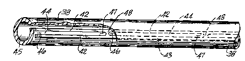
In FIG. 3, the completed drip irrigation hose is shown. Strip 38 is bent along
its length to form
an overlapping longitudinal seam between an interior margin and an exterior
margin of the strip.
Spaced apart, transverse ribs 42 and 43 extend longitudinally through the seam
to connect the margins
of strip 38, forming a seal and a flow regulating passage 44 therebetween. A
water supply passage
45, having a much larger cross-section area then flow regulating passage 44 is
defined by the
remainder of strip 38. Longitudinally spaced apart slits 46 in the portion of
strip 38 between supply
passage 45 and flow regulating passage 44 serve as inlets to flow regulating
passage 44.
Longitudinally spaced apart slits 47, formed in the exterior margin of strip
38, serve as outlets from
the hose. Slits 47 are displaced from the respective slits 46 to provide a
substantial path length from
each inlet to a respective outlet. Preferably, cross ribs 48 are employed to
divide the flow regulating
passage into segments, such that slit 46 is at one end of the segment and a
slit 47 is at the other end
of a segment. Alternatively, the inlets could be formed by interruptions in
rib 42 as illustrated in
FIGS. 5 and 6 of the '051 patent and as illustrated in the '739 patent. The
shape of ribs 42, 43 and
48 are determined by the track pattern on wheel 22 (FIG. 2). Preferably,
chevrons are formed on
the adjacent interior surfaces of ribs 42 and 43 to create turbulent flow in
the flow regulating passage
as illustrated in the '739 patent.
By controlling the length of the slits and the flexibility of the film, water
drips from the outlets
when the hose is pressurized without clogging when the hose is depressurized.
Typically, the line
pressure of the water used for crop irrigation ranges from about 4 psig to 14
psig. Slits 47 are
sufficiently long and strip 38 is sufficiently flexible so the water drips
from the outlets when the hose
is pressurized, rather than squirting. The effective area of the outlets
remains small because the
material on both sides of the slits remain in the same plane, rather than
buckling. If the slits are too
short or the strip is too rigid, the material on either side of the slits does
not move sufficiently to
make a large hole when the hose is pressurized and water squirts out the hose
and erodes the soil.
Slits 47 are sufficient short and strip 38 is sufficiently rigid so the
outlets close completely when the
hose is depressurized. If the slits are too long or the strip is too flexible,
the slits do not close when
the hose is depressurized. Typically, the slits are about 1/4 inch for a 4 mil
film thickness and the
' slits are about 3/8 inch for a 15 mil film thickness. Thus, if the slits are
much shorter than about
1/4 inch for a 4 mil film thickness or if the film is much thicker than about
4 mil for a slit length
of about 114 inch, the water may squirt from the outlets. Similarly, if the
slits are much longer than
about 3l8 inch for a 15 mil film thickness or if the film is much thinner than
about 15 mil for a slit
length of about 3/8 inch, the outlets may not close after the hose is
depressurized.
21~~~~~
WO 94/27728 PCTlUS94/05114
The described embodiment of the invention is only considered to be preferred
and illustrative
of the inventive concept; the scope of the invention is not to be restricted
to such embodiments.
Various and numerous other arrangements may be devised by one skilled in the
art without departing
from the spirit and scope of this invention.