Note: Descriptions are shown in the official language in which they were submitted.
2165010
This invention relates to a structure to enable items, e.g., speakers,
accessolies, etc., to be ~tt~-`h~ to the video display terminal of a co~ ul~r.
For the purpose of this invention, the term "video display tPrmin~l" (VDT) is
used to describe a video display screen connected to a micro-computer which incl~ldes
s a sep~ e box con~ ing coln~uler har.lw~ue, e.g., a central proce-~ing unit (CPU),
and disk drive; or describes a video display screen connect~d to a micro-computer in
which the CPU and disk drive are built into a single unit; or to a "dumb" terminal
in which the video display screen is one of multiple screens electric~lly connected to
a shared CPU.
0 Ml-ltim~i~ pe~:~Ollal COIllpU~ are available which include not only a VDT
for visual displays, but also speakers for an audio output which may be synchronized
to the visual output. In an optimum configuration, a pair of speakers is provided,
with one on each side of the VDT. These have traditionally been mounted on
supports so that their respective positions can be adjusted to give the best audio
reception for an opeldlor sitting before the VDT and keyboard of the computer. Aproblem existed, however, in allt;lll~ling to mount such speakers securely to the VDT.
In the realm of providing speaker attachments to a VDT, U.S. Patents Nos.
5,190,258 and 5,400,408 provided dirrelent solutions to the problem of providingSU~/Oll:i for an audio amplifier housing. On the one hand, U.S. Patent No.
5,190,258, p~tente~ March 2, 1993 by C.C. Yo, provided an articulated support
assembly for audio speakers. It inclll~led a frame, and a post on the frame having a
longit~l~lin~l axis. A first arm was pivotable about the post in a first plane between
a retracted position on the frame and a first angularly extended position. Slide means
were provided for tr~n~l~ting the first arm longitu-lin~lly with respect to the post
``- 216501~
when the first arm was in its angularly-eYtende~ position. A second arm was
pivotable on the first arm about an axis which was perpendicular to the post axis in
a second plane different from the first plane bel~een a retracted position coplanar
with the first arm and a second angularly-extended position. Thus, that patent
pu~olLed to provide for an articulated support assembly for such audio speakers
which was retractable in a recess in the housing of one of the co",puler co",ponents,
e.g., an amplifier.
On the other hand, U.S. Patent No. 5,400,40~, p~t~nte~ March 21, 1995 by
D.A. Lundgren et al, provided a stereophonic sound enclosure system. The enclosure
was used in conjunction with a VDT including an a~ellu,G grill having a first natural
frequency subst~nti~lly within a musical bandwidth, wherein the monitor was coupled
to receive a plurality of video and audio signals from a central processor unit within
a digital information proces~ g system. The hollow body subtended an enclosed
volume and was in the form of a rigid unit including a first plurality of intersecting
rib members for resisting deformation of the hollow body. An audio speaker arrange-
ment was affixed to the hollow body, the audio speaker arrangement being coupledto receive the audio signals and generating in response thereto a plurality of sound
waves. A tuned port was formed within the hollow body which had a second naturalfrequency less than the first natural frequency of the ape,Lu,e grill, and exh~ ted a
band of sele~te~ low frequency sound waves from the hollow body. A plurality of
vibration isolation members was seated on a co,lG~nding plurality of isolation-
mounting s~ ces formed in the hollow body and COI"~,~ ssi~ely-disposed between
the hollow body and the monitor when the hollow body was mounted within the
monitor. Vibration isolation members were provided which had a third natural
2165010
frequency subst~nti~lly equivalent to the second natural frequency. The audio speaker
arrangement was s,~bs~ lly vibrationally isolated from the apellule grill.
The patent liter~tnre also provided some at~L--lpled solutions to the problems
of ~tt~-hing a document holder to a VDT. Examples are the following.
U.S. Patent No. 4,475,705, which issued October 9, 1984 to H.H.
~ennPberg, provided a document holder which was ~tt~h~hle to a VDT to support
one or more documPnt~. The document holder was s,lp~l~ed by an easel bracket
which fit in an annular groove which was preferably formed in the VDT slightly
behind the plane of the screen.
U.S. Patent No. 4,619,429, which issued October 28, 1986 to L.S. Mazza,
provided a copy holder assembly which was mountable onto the VDT of a data
proces~in~ work station. The copy holder included correspondence boards and a
memo board which were coupled to a harness assembly. The harness assembly
included an elastic strap, first and second hinge assemblies and a cross bar. The
elastic strap was lashed around the cabinet bottom and tensioned the hinge assemblies
into co",~lessi~e engagement with the VDT.
U.S. Patent No. 4,632,471, which issued December 30, 1986 to A.H.
Visnapov, provided a copyholder assembly for use with a VDT. The copyholder
included a display framing panel secured to the front of the VDT, and a copyholding
2 o panel extending from a respective side of the display framing panel. The panels were
joined either integrally or for pivotal angular adj~lstn Pnt of the copyholding panel
relative to the display framing panel. The display framing panel, which included a
window which was positionable in front of the VDT, was adjustably det~h~hly
- 2165010
secured to a mounting assembly which was removably securable atop the monitor orto a mount, which was removably securable beneath the monitor.
U.S. Patent No. 4,693,443, which issued September 15, 1987 to J.M. Drain
provided a holder for sheet m~tto.ri~k The holder was secured to the VDT by means
of a hinged mounting. The hinged mounting included a mounting member which was
secured to the VDT by a double-faced adhesive tape. The mounting member includeda cylinder/pin arrangement incll~ing an arm which ~uppol~ed the holder.
U.S. Patent No. 4,869,565, which issued September 26, 1989 to C.S.
Rachm~n, provided a universally-adjustable display d~)l)ald~US for fitment about, and
affixation to, the housing of a VDT. The display appaldlus was secured to the side
faces of the VDT housing by means of adhesive.
U.S. Patent No. 4,902,078, which issued February 20, 1990 to T.W. Judd,
provided a docl-m.~nt holder clip which included a right angle support bracket to be
secured to the side of a VDT. The support bracket was secured to the side of theVDT by means to VELCROTM f~ten~1 to the bracket support, and VELCROTM glued
to the monitor screen case. An extlontling arm was pivotally engaged with the ~uppoll
bracket and a doc~lm~nt holder clip was adaptable for slidable movement on the upper
edge of the extending arm.
U.S. Patent No. 4,960,257, which issued October 2, 1990 to D.F. Waters,
provided a document easel for use with VDT. It included a generally-L-shaped
bracket and a generally-U-shaped member which was removably attached to the VDT.The generally-L-shaped bracket was ~tt~rhed to the VDT by means of a pair of
cooperating adhesive strips.
- 2 1 650 1 0
U.S. Patent No. 5,078,358, which issued January 7, 1992 to R.A. Egly et al,
provided a copy holder having a slotted beam sized to accommodate paper copy. A
paper back ~llpp~ll was hinged to the slotted beam which was pivotally-mounted to
a support bracket which was itself slidably received in a mounting bracket which was
5 secured to a VDT and was adhered to the top of the VDT.
U.S. Patent No. 5,082,235, which issued January 21, 1992 to D.A. Crowther,
et al, provided docum~nt holders for mounting on opposile sides of a VDT. The
mounting was by way of clamps which gripped the exterior opposite side faces of the
VDT and incl~lded a locking adjustable feature.
U.S. Patent No. 5,104,087, which issued April 14, 1992 to D.L. Wentzloff
et al, provided a note/memo board which was particularly constructed to be associated
with an infol.l.alion display device. The note/memo board was provided with an
opening for receiving a housing of the information device. It was removably secured
thereto by way of f~tening means which were releasable. The housing was provided
with strips of VELCRO which were engaged by other strips of VELCRO carried by
a leg of an angle bracket which was adjustably secured to the rear surface of the
note/memo board. Thus, the housing was secured to the outer perimet~r of the VDT
by coopel~tingVELCROTM strips.
U.S. Patent No. 5,104,088, which issued April 14, 1992 to L.J. Bakanowsky
(III), provided a document holder clip which in~ ldecl a right angle support bracket
to be secured to the side of a VDT by two coope~ling VELCROTM strips.
U.S. Patent No. 5,125,612, which issued June 30, 1992 to D.R. McNeal,
provided a bracket for a VDT. The bracket was affixed thereto and held worksheets
- 2165010
for the lelll~inal operator. The bracket was secured both to the top and one side face
of the VDT by coopeldLillg VELCROTM strips.
U.S. Patent No. 5,292,099, p~tpnl~d March 8, 1994 by W.R. Isham et al,
provided a display mounted clocum~-nt holder. It was devised to clamp to a VDT,
S with a documPnt platen on either the right side or the left side, or both sides. The
document holder was secured to the VDT by means of a U-shaped clamp for
co"~l.,essi~ely gripping the sides and top of the VDT.
In the field of ~tt~hing other accessolies to a VDT, the prior art is replete
with add-ons which are not aesthetically pleasing, since they involve brackets secured
to the VDT. Among these patents are:
U.S. Patent No. 4,946,121, which issued August 7, 1990 to J.T. Troke,
provided a bracket accessory for mounting on a VDT for tell~ol~ry storage of a
keyboard. Each bracket had a pair of fingers which defined a bight. A pair of such
brackets was mounted on a VDT so that the bights were located above the VDT and
opened upwardly and were aligned horizontally. The brackets were ~tt~r.hecl to the
VDT using double-faced pr~s~u~-sensitive adhesive tape.
U.S. Patent No. 5,035,392, p~nted July 30, 1991 by C. Gross et al,
provided a VDT. The ~tt~chm.ont mech~ni~m was for mounting a display board on
either or both sides of a the VDT. Each such display board was pivotable around
2 o both horizontal and vertical axes to provide maximum comfort for the VDT operator.
The holder was secured to the VDT by means of a base plate which was secured to
two corner shoulders.
U.S. Patent No. 5,320,328, p~t~nted June 14, 1994 by T-S Chen, provided
a filter screen mounting device for a VDT which included a mounting block. The
- 2 1 650 1 0
mounting block was secured to the top of the VDT by means of VELCRO~M or a
self-sticking pad.
U.S. Patent No. 5,328,145, p~lPn~e~ July 12, 1994 by D.R. Charapich,
provided a mounting board for a VDT housing which was a planar sheet having an
opening for viewing the VDT in one portion. The mounting board was ~tt~hed to
the VDT housing by stabilizers. The stabilizers can be positioned to accommodatefor variations in VDT housings. The stabilizers were secured to the VDT frame bymeans of double-faced adhesive tape.
U.S. Patent No. 5,398,905, p~tent~ March 21, 1995 by L.A. Hinson,
l o provided a die-cut display board for a VDT. The display board included a top screen
housing tab and a side screen housing tab. Such tabs were f~tene~ to the VDT by
double-sided adhesive tape, or by VELCROTM.
Of the prior patents ~i~c~ ed above, U.S. Patent No. 4,475,705 provided a
bracket complPm~nt~ry to the width and shape of an annular groove formed in the top
of the VDT between the cover and the bezel.
Accordingly, the present invention has for its principal object, the provision
of cooperative el~m~nt~ associated with a VDT to allow easy additions and removal
of a wide variety of items thereto.
An object of another aspect of this invention is to provide such elemPnt~ which
are as inconspicuous and :lesthP,ticz~lly ple~ing as possible.
An object of a further aspect of the present invention is to provide a mounting
structure for slidingly receiving and seCllrin~ a holder in place for removably
~e!~inillg items at desired locations on the VDT.
`- 2 1 650 1 0
An object of yet another aspect of the present invention to provide such
cooperative elements whereby the items can be mounted to the VDT without requiring
any tools and with minimum effort.
An object of still another aspect of the invention is to provide such cooperative
Pl~nn~ntc whereby the items can be quicldy in~t~ d onto a VDT and which can be
easily removed.
According to a broad aspect of the invention, an accessory may be secured to
a video display terminal by means of a peripheral grooved channel operatively
~Csoci~tpA with the side edges and the top edge of the video display terminal. An
element is provided which has a complem~o-nt~ry flange dçfining a groove for securing
cooperation within the grooved çh~nnPl The acccssoly is secured, either directly or
indirectly, to the video display termin~l by securing cooperation between the grooved
ch~nn~l and the flange dçfining the complenn~nt~ry groove.
Thus, by one broad aspect of this invention, means are provided for securing
an accessoly to a video display terminal comprising: a peripheral grooved channel
operatively ~ccoci~t~d with the side edges and the top edge of the video displaylell"illal; and an element provided with a complement~ry flange d~fining a groove for
seCuring cooperation within the peripheral grooved channel; whereby the accessory
is secured to the video display terminal by securing cooperation between the
2 o peripheral grooved ch~nnPl and the flange dçfining the complçment~ry groove.
By one specific aspect of this broad aspect of this invention, means are
provided for securing an accessory to a video display terminal compricing: a
peripheral grooved çh~nnel provided within the side edges and the top edge of the
video display terminal; and an accessory provided with a complemçnt~ry flange
2165010
definin~ a groove for securing coo~l~lion within the pc;liph~ldl grooved ch~nnPl;
whereby the accessoly is directly secured to the video display te~min~l by securing
cooperation between the peripheral grooved ch~nnPl and the flange ~efinin~ the
complemPnt~ry groove.
By another specific aspect of this broad aspect of this invention, means are
provided for securinE an accessoly to a video display terminal comprising: a
rectangular framework complemP-nt~ry to the video display terminal and being of
s,~sl~n~;~lly the same ~imçn~ions as the front face ~imPn~ion of the video display
terminal for s~;ul~;l-lent to the front face of the video display terminal, the framework
lo including a peripheral grooved çh~nnel within the side edges and the top edge of the
rectangular framework; and an PlPmPnt provided with a complementary flange
defining a groove for securing cooperation with the peripheral grooved ch~nnPl;
whereby the accessory is indirectly secured to the video display terminal by securing
cooperation between the peripheral grooved ch~nnel and the flange defining the
complemP-nt~ry groove.
By one variant of this invention, the framework includes a stepped larger rear
portion, the peripheral area on the stepped larger rear portion which surrounds a
forward portion being provided with the peripheral grooved ch~nnPl.
By a variant of these aspects of the invention, at least one face of the
peripheral grooved ch~nnP-l is provided with frictional gripping surfaces, e.g., where
the frictional gripping surface~s are upstanding from the base of the pelipheldl grooved
ch~nnP.l
By another variant of these aspects of this invention, the ~lemPnt which is
provided with the complementary flange defining the groove comprises: a bracket
2165010
having a compl~, IP~ . y flange defining a groove on one side edge thereof and a rear
flange at its oppo~ilt; edge for securing cooperation with the grooved ch~nnPl, the
bracket having means thereon for the securement of the ~ce~o. y thereto.
By yet another variant of these aspects of this invention, the elemPnt provided
with the complemP-nt~ry groove compri~es: the accessory which has the
complementary flange defining a groove on one side edge thereof and a rear flange
at its opposite edge for securinp cooperation with the grooved channel.
By still another variant of these aspects of the invention, the ~lement which
is provided with the comple-llt~ . y groove comprises the accessuly, the accessory
including a complemP-nt~ry flange defining a groove along one side edge of the
accessory and a rear bracket at the other side edge thereof.
By yet a further variant of these aspects and variants of the invention, the
grooved channel ~oci~t~d with the video display tube comprises a female channel,and the compl~m~.nt~ry flange de.fining a groove comprises a male groove.
By yet a further variant of the aspects and variants of this invention, an anti-glare filter is ~soci~ted with the video display terminal.
The present invention thus provides a system for ~tt~ching accessories to a
compuler monitor. In one embodiment, the system includes a peripheral frame
having two sides and an upper waU e~t~-n-ling perpendicularly the~;flo-ll. The front
2 o of the frame may be fitted with an anti-glare filter. The side panels of the frame are
provided with peripheral female grooved çh~nntol~ The frame is adapted to be
secured by interior adhesion means to the front face of the VDT, so as to provide a
peripheral female çh~nne] having frictional gripping s~ xs on one face thereof
between the frame and the VDT. In another embodiment, the VDT box itself is
2165010
11
provided with grooved ch~nnele, along the side edges and the top edge thereof.
Either a bracket, or the accessoly itself, has a complemPnt~ry grooved male ch~nnel
which is adapted to be fitted into the peripheral female grooved ch~nnPl, to be
gripped by the female grooved ch~nnPl and by its ~eeoci~tPcl frictional grippings~rf~ee. If the brackets are used, the bracket are further provided with means
cooperating with the accessGly to hold the ~ce-s~o~y to the VDT.
In the acco.,lpanying drawings,
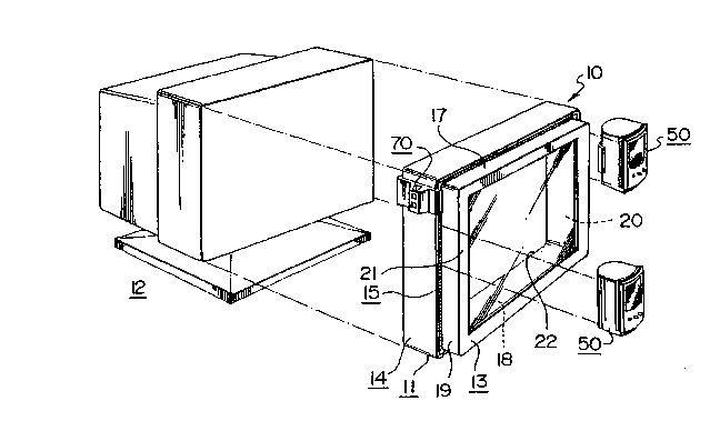
Fig. 1 is an exploded front perspective view of the system of one embodiment
of this invention associated with the video display terminal, which is shown in block
sch~n ~tic form;
Fig. 2 is a rear perspective view of the assembled system of one embodiment
of this invention;
Fig. 3 is a front elevational view of the peripheral female channel of the
system of an embodiment of this invention;
Fig. 4 is a section through line IV-IV of Fig. 3;
Fig. 5 is a top plan view of a speaker ~tt~-hed to the video display l~ inal
provided with the system of an embodiment of this invention; and
Fig. 6 is a top plan view of a bracket ~tt~hed to the video display te,.llillal
provided with the system of an embodiment of this invention.
As seen in Figs. 1 and 2, the system 10 of this invention is in the form of a
box-like frame 11. As seen in Fig. 1, the frame is adapted to be secured by interior
conventional means, e.g., by double-faced adhesive tape or by VELCROTM (not seen)
to a video display tel~ al box 12 (shown in schPm~tic form).
2165010
12
As seen in Figs. 1 and 2, the box-like frame 11 inçh-des a face portion 13 and
a rear portion 14, which is slightly larger and which defines a peripheral space 15
between face portion 13 and rear portion 14. The peripheral space 15 includes a
backing block 16 (seen in Fig. 2).
Face portion 13 in~.ludes a peripheral frame defined by a pair of parallel upperand lower plates 17,18 and a pair of parallel uprights 19,20. A facia defined byenclosing open rectangular framework 21 is provided at the lateral edge of plates
17,18 and uprights 19,20. It is ~lc;fel~d that an anti-glare filter 22 be provided
within the open framework 21, which is held in place by clamp 23.
o Rear portion 14 includes a peripheral frame defined by an upper plate 24 and
a pair of parallel uprights 25,26. The peripheral space 15 between face portion 13
and rear portion 14 is provided with a peripheral female grooved channel 27 which
is seen more clearly in Figs. 3, 4 and 5.
In the operation of the invention, the appa-d~us 10 is secured to the front faceof the video display terrninal 12, as seen in Fig. 1.
As seen more clearly in Figs. 3 and 4, the ch~nn~l 27 is defined at outer
lateral edge by peripheral lateral face 29, defined by the front edges of plate 24 and
uprights 25,26, and at its limiting inner edge by peripheral surfaces 29 defined by
plate 24 and upri~ht~ 19,20. The l~.h~nnel 27 incl~ldes a peripheral base 30, provided
with a plurality of parallel, upst~n-ling, friction-enh~ncing, projecting s~ ces 31.
Fig. 5 shows an accesso~y 50 (e.g., a speaker) secured to the system 10 of this
invention. As noted before, the peripheral female grooved çh~nnel 27 is defined by
inner and outer lateral edges 28,29 and has a base 30 provided with ~Ipst~ntlingfriction enhancing surfaces 31.
2165010
13
The speaker 50 includes a rear bracket 51 and a forward complementary male
ch~nnel 52. Male çh~nnel 52 includes an inner peripheral face 53 and a male flange
54. The space 55 between pe,iph~l~l face 53 and male flange 54 provides the
complemP.nt~ry groove. The projecting face of male flange 54 is provided with a
plurality of parallel in-lent~t1Qns 56 which are complem~-nt~ry to projecting surf~r.es
51.
If a speaker 50 is to be secured to a side of the video display terminal 12, thespeaker is secured by first placing the cG-,-plem~nt~ry grooved male channel into the
peripheral female to provide the cooperation shown in Fig. 5. The rear bracket is
then secured by friction against the rear face of the rear portion of the system of
embo-lim~-nt.~ of this invention. It is plcfelled that the complementary cut-outs mate
with the projections.
As seen in Fig. 6, a bracket 70 may also be secured to the system 10 of this
invention. The bracket 70 has a main rectangular base 71. The base 71 includes arear flange 72 and a forward complem~nt~ry male çh~nnel 73. Channel 73 includes
an inner peripheral face 74 and a male flange 75. The space 76 between peripheral
face 74 and flange 75 provides the complemP.nt~ry grooved ch~nnP.l The projecting
face of the male flange 75 is provided with a plurality of parallel inden~tions 76
which are comple",~ ,y to projecting surfaces 51.
Base 71 includes a projecting bushing 77, which includes a hollow cylin-1ric~l
core 78 thelGl}~ugh. This core ~iU~ S the cylindric~l shaft of a desired ~ce~o, y.
One such ~ccçs.~o,~ which may be used is the single sheet paper holder shown anddescribed in U.S. Patent Design No. 309,603.
2165010
14
If a bracket 70 is to be secured to a side of the video display terminal 12, thebracket is secured by first placing the complementary grooved male çh~nnel into the
peripheral female çh~nn~l to provide the coope~dlion shown in Fig. 6. The bracket
is then secured by friction of the rear flange against the rear face of the rear portion
of the system of the invention. It is pl~,ed that the complementary cut-outs mate
with the projection. A suitable accessol~y, also as shown in Fig. 6, may then be~tt~hed.