Note: Descriptions are shown in the official language in which they were submitted.
65~5
STEAM MOISTENING APPARAT~S
BACKGRO~ND OF THE INVENTION
1. Field of the Invention
The present invention relates to a steam moistening
apparatus with a housing which includes a steam connection and in
which a steam blow chamber is arranged, wherein the steam blow
chamber has an external wall in common with the housing and the
external wall is provided with steam outlet openings.
,--
2. Description of the Related Art
Steam moistening apparatus of this type have the purpose of
directing steam against material webs travelling past the
apparatus in order to increase the moisture and temperature of
the material webs. A widespread field of use is the manufacture
or processing of paper webs in which such steam moistening
apparatus are used in connection with calendars or other roll
arrangements. In these arrangements, steam is directed against
the paper web before the paper web travels through a roll gap, in
order to improve the gloss or the smoothness, to change the bulk
or the density or to increase the moisture.
-J~
h~ ~
~ ,
6 5 ~1 ~ 5
A steam moistening apparatus known from DE 43 09 076 A1,
constructed as a steam spray pipe, includes a steam blow chamber
which is divided into several sections or zones in transverse
direction, i.e, over the width extending in the direction of a
material web travelling past the apparatus. Each zone has a
valve which permits steam to flow from the interior of the
housing into the steam blow chamber in each zone. An
acceleration duct is arranged between the valve and the steam
blow chamber, wherein a supply duct branches off from the steam
blow chamber at a predetermined distance from the end of the
acceleration duct.
Another steam moistening apparatus known from DE 41 25 062
A1, constructed as a steam blow box, includes a steam blow
chamber which is also divided into zones in transverse direction,
wherein each zone has its own valve for admitting steam into the
steam blow chamber. The steam entering the steam blow chamber
had first been used for heating at least one of the walls of the
steam blow chamber. Before the steam is used, it is dried in a
steam drying section.
Steam moistening apparatus of this type have the advantage
that the discharged steam quantity can be adjusted differently at
least from zone to zone transversely of the machine direction.
~A
-- .
5 ~ ~ 5
However, the apparatus have the disadvantage that they are
complicated and, thus, expensive because of the large number of
valves of the moistening apparatus. If a single moistening
apparatus is not sufficient for directing steam against a side of
the material web, for example, when operated at the limit of its
capacity, frequently two or more moistening apparatus are used.
However, in that case, it is no longer necessary to equip all
moistening apparatus with separate controllable zones. Rather,
it is sufficient when it is possible to change the total quantity
of steam discharged by the steam moistening apparatus. It is
then possible to achieve a uniform discharge of steam in
transverse direction of the machine, i.e., transversely of the
travelling material web, by means of a single steam moistening
apparatus which can be controlled zone by zone.
..
A
1 65~5
SUMMARY OF THE lNv~N-lION
Therefore, it is the primary object of the present invention
to provide a steam moistening apparatus of the above-described
type which can be reliably operated without a zone-by-zone
control.
In accordance with the present invention, in the interior of
the housing of the steam moistening apparatus of the above-
described type, is arranged a distribution duct to which steam
can be admitted and which is continuously surrounded by steam on
all sides, wherein the distribution duct is in communication with
the steam blow chamber through several supply lines which are
distributed over the length of the housing.
The distribution duct is arranged essentially parallel to
the steam blow chamber. Of course, the definition of having the
distribution duct surrounded on all sides by steam still permits
interruptions of the steam surroundings, as they may be required,
for example, by a fastening means of the distribution duct in the
housing. The distribution duct is continuously heated, i.e.,
also when operation of the apparatus is interrupted. After
shutdowns, i.e., when the steam moistening apparatus is also
switched off, an initial heating phase is required during which
1 ~
.
~ 1 65~5
the distribution duct is continuously surrounded by steam before
steam can be admitted to the material web from the steam
moistening apparatus.
The configuration of the steam moistening apparatus
according to the present invention makes it possible, on the one
hand, to distribute the steam relatively uniformly over the
length of the width of the moistening apparatus. This is because
the distribution duct ensures that the steam is initially
distributed once over the width, i.e., in transverse direction of
the machine, before the steam is supplied to the steam blow
chamber. Accordingly, each section over the width of the
apparatus receives the same quantity of steam under the same
pressure. Consequently, by the omission of a zone-by-zone
control of the steam blow box, there at least occurs no
deterioration of the intended result of the application of steam,
i.e., moisture, gloss or smoothness or the like.
However, another positive effect can be achieved by the
distribution duct. Contrary to steam blow boxes which are
controlled zone-by-zone and in which a valve is arranged at each
zone for controlling the supply of steam into the zone, such zone
valves are not provided in the steam moistening apparatus
according to the present invention. Rather, only one or two
*'A^~ '
~d~ 65(J~5
valves are provided which control the entire steam supply to the
moistening apparatus. Consequently, these valves cannot be
located immediately adjacent to the zones.
When the operation is interrupted, as it may occur, for
example, when exchanging a roll in a calendar, when changing a
material web roll or also in other cases, the necessary heat
supply to the steam moistening apparatus is usually no longer
ensured. When starting up the apparatus after the interruption,
this has the result that the steam which was actually intended
for applying steam to the material web initially condenses in the
moistening apparatus. The discharge of the condensate is
usually no problem, however, as soon as condensate, i.e., water
is present in the steam moistening apparatus, there is the danger
that the steam flowing through the apparatus entrains water
droplets and transports the water droplets onto the material web.
Since the steam is to be blown with relatively high speeds
against the material web, in order to be able to direct the
desired amount of steam against the material web which travels at
a high speed, this results in correspondingly high speeds of the
water droplets. The water droplets then act as bullets which
perforate the material web or damage the material web in some
other manner. In accordance with the present invention, this
A
~ 1 651~5
problem has now essentially been eliminated by the configuration
of the apparatus with a distribution duct.
Heating of the distribution duct ensures that the steam is
raised to the necessary temperature before entering the steam
blow chamber. Accordingly, even if the steam still should
contain some water, this water is very likely to be vaporized at
the latest in the distribution duct. Accordingly, for
controlling the steam supply to the steam blow chamber, such a
steam moistening apparatus can be equipped with a valve which is
spatially removed from the steam moistening apparatus. It is now
possible that the supply for the process steam, i.e., the steam
which is used for moistening the material web, can cool during
production stops; in addition, it is acceptable that the process
steam contained in the supply can condense. However, since the
distribution duct is continuously heated and maintained at a high
temperature, when the apparatus is restarted, the process steam
is heated at the latest in the distribution duct to such an
extent that the water can vaporize, so that the danger of water
droplets damaging the material web is significantly reduced. It
is now also possible to operate such apparatus in an upside-down
configuration, i.e., with the steam being discharged toward the
bottom; in the past, this was not easily possible because water
of condensed steam could drop onto the web.
_.
65~ j5
In accordance with a preferred further development of the
present invention, the cross-sectional area of the distribution
duct is greater than the sum of the cross-sectional areas of all
supply lines. This feature makes it possible in a simple manner
that the steam is initially uniformly distributed in the
distribution duct before it enters the steam blow chamber. By
adhering to the stated dimensions, the cross-sectional area of
the distribution duct may be uniform over the width of the
apparatus, without leading to pressure drops which would impair
the supply to the steam blow chamber in certain sections.
In accordance with another preferred feature, at the
locations where the supply lines open into the steam blow
chamber, the axis of each supply line extends essentially
perpendicular to a baffle wall located opposite the supply line.
This configuration represents an additional safety measure.
Water droplets which have reached the steam blow chamber in spite
of all previous measures, are initially reflected back into the
entering steam jet in which they are in all likelihood vaporized.
Moreover, this configuration provides significant advantages with
respect to the reduction of the noise level which is generated
when the discharged steam flows toward the material web.
~ 1 65~5
In accordance with another preferred feature, the baffle
wall extends essentially at a right angle to the external wall.
This means that the water droplets must carry out another change
of direction before they can be discharged through the steam
outlet openings. However, a certain time is required for this
change in direction which leads to an increase in the period of
time in which the water droplets are within the steam blow
chamber. It is very likely that the water droplets vaporize
during this time. It must be emphasized in this connection that
the heated distribution duct has already drastically reduced the
risk of water droplets reaching the steam blow chamber at all.
The additional measures described above are really only intended
for rare exceptions.
Another preferred feature provides that the supply lines
extend with a predetermined length into the interior of the
distribution duct. This means that steam can only be removed
from the interior of the distribution duct and not from the wall
areas thereof. However, because of their mass, water droplets
will predominantly precipitate at the walls of the distribution
duct located at the bottom in the direction of gravity, so that
it can be assumed that an essentially water-free steam is present
in the interior of the distribution duct, i.e., at a distance
from the walls of the distribution duct. Moreover, this
6 ~ 5
configuration also makes possible the discharge of steam in a
downward direction. In that case, the supply lines extend out of
the distribution duct in a downward direction. However, the ends
of the supply lines projecting into the interior of the
distribution duct ensure that water collecting at the bottom of
the distribution duct, i.e., on the bottom wall in the direction
of gravity, will not enter the supply lines.
The supply lines preferably have a bend between the supply
duct and the steam blow chamber, wherein the bend extends over an
angle of approximately 90. Since the supply lines are also
loaated in the interior of the housing and are surrounded by
steam, this measure means a small further extension of the length
along which the steam is guided through a heated environment. In
addition, the bend makes it possible in a simple manner to
produce the desired direction of the steam when entering the
steam blow chamber. Moreover, when flowing through the bend, any
possibly remaining water is thrown by the centrifugal force
against the heated wall of the bend and is vaporized. The bend
additionally produces the advantageous effect of noise reduction.
The locations at which the supply lines open into the steam
blow chamber are preferably spaced from each other at essentially
equal distances. This simple measure produces a relatively
A~
.
1 6 5 ~ '~ 5
uniform supply of steam to the steam blow chamber and the
attendant uniform steam discharge in transverse direction of the
machine.
In accordance with a particularly preferred feature, the
distance between the end of the steam blow chamber and the
opening of the next supply line into the steam blow chamber is
approximately half the distance between adjacent openings of
supply lines. When the steam blow chamber is considered to be
divided into zones, each of the supply lines opens approximately
in the center of each such zone. In this manner, a uniform
distribution of the steam can be ensured in a simple manner.
The distribution duct preferably has a steam inlet, wherein
the distance of each supply line from the steam inlet is at most
half the length of the distribution duct. This measure also
contributes to a uniform distribution of the steam in the steam
blow chamber. The distance which must be travelled by the steam
is kept as short as this is possible with simple means.
In accordance with a particularly preferred embodiment, the
housing has a heating steam connection and the distribution duct
has a process steam connection which is separate ~rom the heating
steam connection. The heating steam connection can be connected
-
~ 1 65~5
permanently to steam supply, so that the interior of the housing
is filled with hot steam. This steam serves for heating the
distribution duct and also for heating the steam blow chamber
which may also be arranged in the interior of the housing. The
temperature of the steam can be controlled relatively easily
through the pressure at the heating steam connection. The
quantity of steam fed into the distribution duct can be
controlled through the process steam connection which is provided
with a valve for this purpose. This valve no longer has to be
arranged in the immediate vicinity of the moistening apparatus.
This may be particularly advantageous where the available space
is narrow, for example, in material web pockets for deflecting
the material web between roll gaps. Rather, a longer supply line
is acceptable, even if there is the risk that the steam in the
line cools and condenses during interruptions of the production.
When the moistening apparatus is started or restarted, this water
is transported into the steam moistening apparatus. However,
since the latter is heated, particularly in the area of the
distribution chamber, the water is essentially vaporized.
In accordance with another preferred feature, the process
steam connection has an inlet duct extending within the interior
of the housing, wherein the inlet duct is connected to the
distribution duct through a connecting duct which ends
~Al ,
~ 1 65~'~5
approximately in the middle of the distribution duct.
Consequently, the process steam is heated already immediately
after entering the housing; specifically, heating occurs in the
inlet duct. This contributes to a further reduction of the
problems which might occur when water droplets are entrained in
the steam. It must only be ensured that the capacity of the
inlet duct is adapted to the quantity of the expected water.
It is particularly advantageous in this connection that the
inlet duct is constructed as a steam drying section. The drying
of steam can be effected, for example, by increasing the cross
section of the inlet duct as compared to the process steam
connection. As a result, the flow velocity of the entering steam
is reduced and water which enters with the steam in the inlet
duct can be precipitated and deposited relatively problem-free on
the bottom of the inlet duct.
This effect can be improved in a preferred embodiment by
forcing the steam to carry out at least one change of direction
in the flow path in the inlet duct. Such a change of direction
is carried out without problems by the steam. However, the water
droplets which because of their mass have a greater inertia, will
initially resist such a change in direction. In other words, the
water droplets have the tendency of travelling straight ahead.
If, for example, a wall is provided in this direction of
movement, the water droplets will be caught by this wall and will
flow downwardly. In this manner, water droplets are mechanically
removed from the steam.
In accordance with an alternative or additional measure, it
may be provided that the connecting duct branches off from the
inlet duct essentially at a right angle and at a predetermined
distance in front of the end of the inlet duct. This change of
direction produced by the connecting duct provides an obstacle
for the water droplets. As a result of the inertia of the water
droplets, they initially travel straight ahead. Since the inlet
duct continues for a small distance following the connection with
the connecting duct, the water droplets can continue to travel in
this direction. The water droplets are then collected at the end
of the inlet duct in a type of pocket and can be discharged from
the pocket.
In accordance with another preferred embodiment, the
distribution duct has at least one inlet valve whose steam-
conducting components are arranged in the interior of the
housing, wherein steam travels through the inlet valve from the
interior of the housing into the distribution duct. In that
case, the process steam, i.e., the steam used for the treatment
A~
1 65~5
of the material web, is taken from the heating steam. However,
in this embodiment it is also ensured that the distribution duct
is permanently heated by the steam. In that case, steam is
present all the way to the steam moistening apparatus even when
production is interrupted. This substantially reduces the danger
that the water cools and condenses in a supply line. Since the
inlet valve is arranged at least with its steam conducting
components in the interior of the housing, it is ensured that
these components are also permanently heated, so that again there
is no danger that the steam cools and condenses.
In accordance with a particularly preferred feature, an
inlet valve each is arranged in the area of each end of the
distribution duct. In some cases, more space is available in the
areas of the ends than in the middle of the steam moistening
apparatus. Since two inlet valves are used, a relatively uniform
steam distribution can be achieved.
The various features of novelty which characterize the
invention are pointed out with particularity in the claims
annexed to and forming a part of the disclosure. For a better
understanding of the invention, its operating advantages,
specific objects attained by its use, reference should be had to
~ 1 6S~5
the drawing and descriptive manner in which there are illustrated
and described preferred embodiments of the invention.
. ~_
, .s
~ 1 65~5
BRIEF DESCRIPTION OF THE DRAWING
In the drawing:
Fig. 1 is a cross-sectional view of a first embodiment of a
steam moistening apparatus according to the present invention;
Fig. 2 is a top view of the steam moistening apparatus of
Fig. l;
.
Fig. 3 is a partial sectional view taken along sectional
line III-III of Fig. 1;
Fig. 4 is a cross-sectional view of a second embodiment of
the steam moistening apparatus according to the present
invention;
Fig. 5 is a view according to V-V of Fig. 4;
Fig. 6 is a diagram showing the steam flow in the first
embodiment of the steam moistening apparatus; and
Fig. 7 is a diagram showing the steam flow in the second
embodiment of the steam moistening apparatus.
I 65~
DETAILED DESCRIPTION OF T~E PREFERRED EMBODIMENTS
As illustrated in Fig. 1 of the drawing, a steam moistening
apparatus 1 has a housing 2 with an interior space 3. A U-shaped
housing wall 4 is integrally formed in the interior space 3.
Together with a diffusor plate 5, the housing wall 4 forms a
steam blow chamber 6. The diffusor plate 5 has a plurality of
steam outlet openings 7.
The steam blow chamber 6 is connected to a distribution duct
9 through a plurality of supply lines 8. Each supply line 8
extends with its opening 10 into the steam blow chamber 6 in such
a way that the axis 11 of the opening 10 extends essentially at a
right angle to an opposite wall of the steam blow chamber 6,
wherein this opposite wall will be called a baffle wall 12 in the
following. The baffle wall 12, in turn, extends at a right angle
to the diffusor plate 5.
The supply line 8 extends with a certain length 13 into the
interior of the distribution duct 9. Accordingly, steam can
reach the supply line 8 only from the interior of the
distribution duct 9. Any water which may precipitate at the
walls of the distribution duct 9 is prevented from entering the
supply line 8.
65~5
As particularly illustrated in Fig. 2, the distribution duct
9 is connected to an inlet duct 15 through a connecting duct 14
which forms a steam inlet. The inlet duct 15 has a process steam
connection 16 through which steam, which is to be used for
moistening a material web, not shown, is supplied to the inlet
duct 15. The inlet duct 15 is constructed as a steam drying
section. The drying of steam is achieved by two measures.
First, the cross-sectional area of the inlet duct 15 is
substantially greater than the cross-sectional area of the
process steam connection 16. This means that the flow velocity
of the steam in the inlet duct is reduced as compared to the flow
velocity of the steam in the process steam connection 16, so that
any water entrained in the steam can drop down. In addition,
intermediate walls 17 with openings 18 are provided in the inlet
duct, wherein the intermediate walls 17 force the steam to change
its direction, as indicated by arrows 19. The steam can carry
out the changes of direction in accordance with arrows 19
essentially without problems. However, any entrained water has
the tendency to travel straight ahead because of its greater
inertia. The water impinges on the walls 17 and flows down on
the walls 17 in the direction of gravity. A possibility for
draining the water may be provided at each intermediate wall 17.
For example, the water may be drained by means of a siphon.
_
A~
~J ~ 6 5~ 5
However, it is also possible alternatively to collect the water
flowing down at all walls 17 and to discharge this water.
As an additional measure for drying the steam it may be
provided that the connecting duct 14 branches off at a certain
distance in front of the end of the inlet duct 15. The
connecting duct 14 may branch off essentially at a right angle.
As a result, the inlet duct 15 forms at its end a kind of pocket
20 in which remaining water droplets can be collected. A means
for discharging the water may be provided in the pocket 20.
The housing 2 further includes a heating steam connection 21
through which steam can be admitted into the interior space 3 of
the housing 2. Depending on the pressure at the heating steam
connection 21 and, thus, depending on the pressure of the steam
in the interior space 3 of the housing 2, a certain temperature
will prevail in the interior space 3. Consequently, the steam
contained in the interior space 3 of the housing 2 heats the
inlet duct 15 as well as the distribution duct 19. In addition,
the supply lines 8 and the three walls of the steam blow chamber
6 are heated by the heating steam. Accordingly, even if water
droplets travel through the process steam connection 16 into the
inlet duct 15, the connecting duct 41, the distribution duct 9,
the supply lines 8 or the steam blow chamber 6, it is very likely
21
A~
65~5
that the water droplets evaporate. The likelihood that water is
still contained in the steam decreases with increasing travel
towards the steam blow chamber 6. As a result, the likelihood
that water is still in the steam in the steam blow chamber is
practically zero. Any water droplets which nevertheless have
travelled all the way into the steam blow chamber 6 are initially
directed against the heated baffle wall 12, where they can
evaporate. If they do not evaporate, they are reflected back
into the arriving steam jet. As a result of the configuration
illustrated in the drawing, the time the water droplets remain in
the steam blow chamber 6 can be increased to such an extent that
the water droplets will evaporate in the steam blow chamber 6
with a likelihood which borders on certainty and cannot be
discharged through the openings 7 of the diffusor plate 5.
The distribution duct 9 has a cross-sectional area which is
greater than the sum of the cross-sectional areas of all supply
lines 8. As a result, a relatively uniform steam pressure will
build up in the distribution duct 9, wherein this pressure is no
longer dependent on the distance from the connecting duct 14.
This dependency is further decreased as a result of the fact that
the maximum distance of a supply line 8 from the connecting duct
14 corresponds to half the length of the distribution duct 9.
This means that the distance which must be travelled by the steam
A
~ ~ 1 65~5
from the connecting duct 14 to the supply line 8 which is
farthest away, is kept as short as possible.
Since the inlet duct 15 extends approximately into the
middle of the distribution duct 9, the steam must travel half the
width of the steam moistening apparatus 1 before it can enter the
distribution duct 9. However, this entire section is already
heated, so that any water still contained in the steam can
evaporate. Any additional water which still has not been
evaporated or which has been separated by the intermediate walls
17 can then evaporate in the distribution duct 9.
The drawing schematically shows a plurality of drainage
openings 22. However, such drainage openings are known in
connection with steam blow boxes. The openings 22 may be
connected, for example, to a siphon or an appropriate valve for
allowing water to be discharged without loss of pressure.
A steam moistening apparatus 1 of this type can be operated
with a remote valve, not shown, which controls the total steam
discharge by the steam moistening apparatus 1. When the valve is
closed, for example, during an interruption of production, the
line between this valve which is not illustrated and the steam
moistening apparatus 1 will cool down. The steam contained in the
6 5 ~ '~ 5
apparatus will condense. When the steam moistening apparatus 1
is restarted, the corresponding quantity of water, for example,
0.5 or 1 l, will reach the inlet duct 15. Since the inlet duct
15 is constructed as a steam drying section, the water will be
already essentially removed in this section, partially by
mechanical measures, such as, the intermediate walls 17 and the
pocket 20, and partially by heating. Any water still remaining
will then evaporate in the distribution duct 9 which is heated
over its full circumference.
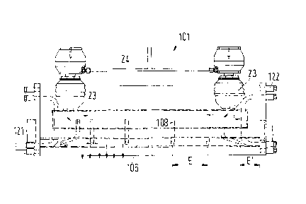
Figs. 4 and 5 show another embodiment of the steam
moistening apparatus according to the present invention, wherein
corresponding components are provided with the same reference
numerals except that they are increased by 100. Any components
which are the same as in the embodiment shown in Figs. 1 - 3 will
not be discussed once again.
Contrary to the embodiment of Figs. 1 - 3, the steam
moistening apparatus 101 is arranged in such a way that the steam
is discharged downwardly in the direction of gravity.
Consequently, the diffusor plate 105 which forms the outer wall
of the housing 102 in this area is arranged at the bottom in the
direction of gravity. Also, the supply line 108 opens into the
distribution duct 109 in a downward direction. Even if water is
A
1 6`~ 5
collected in the distribution duct 109, this water cannot flow
into the steam blow chamber 106 because the end 113 of the supply
line 108 extends into the distribution duct 109.
In this embodiment, the distribution duct 109 does not have
a separate process steam connection. Rather, only a single steam
connection 121 is provided for supplying steam to the interior
space 103 of the housing 102.
Two valves 23 are provided for supplying steam to the
distribution duct 109. The steam-conducting components of the
valves are arranged in the interior space 103 of the housing 102.
The valves 23 form inlet valves for the distribution duct 109,
i.e., the valves 23 control the steam supply from the interior
space 103 of the housing 102 into the distribution duct 109.
However, also in this case, the distribution duct 109 is
surrounded by steam permanently and over its full circumference.
The flow path of the steam is indicated by arrows.
In this embodiment illustrated in Figs. 4 and 5, the valves
23 are arranged in the areas of the two ends of the distribution
duct 109. Consequently, also in this case, the maximum distance
from the entry into the distribution duct 109 to the farthest
5 (~ ~ 5
remote supply line 108 corresponds to half the length of the
distribution duct 109.
As is apparent from Fig. 5, the distances E between adjacent
openings of the supply lines 108 into the steam blow chamber 106
are essentially e~ual. The distance E' between the supply line
108 which is located closest to the end of the steam blow chamber
106 corresponds approximately to half the distance E.
Accordingly, the individual supply lines 108 all open into the
steam blow chamber 106 in the center of imaginary zones, wherein,
however, the steam blow chamber 106 is not actually divided into
zones and the zones cannot be controlled individually.
Fig. 6 schematically shows the path of the steam from a
steam source 25 to the steam moistening apparatus 1. A pressure
regulator 26 is arranged following the steam source 25, for
example, a steam boiler; the pressure regulator 26 is provided
in the conventional manner with a valve 27 which keeps constant
the pressure at the output 30 of the pressure regulator 26
through a drive 29 controlled by a regulator 28. The regulator
or convertor 28 obtains its measurement values through a sensor
31.
The steam line 32 is divided following the pressure
regulator 26. One branch 33 is connected directly to the heating
steam connection 21 of the steam moistening apparatus 1.
Accordingly, at the heating steam connection 21, steam is
permanently present at a temperature determined by the pressure
regulator 26.
Another branch 34 of the steam line 32 is connected to the
process steam connection 16. A valve 35 is arranged in this
branch 34, wherein the valve 35 controls the supply of process
steam, i.e., the quantity of the steam to be conducted against
the material web.
Fig. 7 schematically illustrates the path of the steam in
the embodiment of the apparatus 101 shown in Figs. 4 and 5. A
steam source 25 is provided also in this embodiment with a
pressure regulator 26 downstream of the pressure source 25. The
output 30 of the pressure regulator is connected through the
steam line 32 directly to the heating steam connection 121 of the
steam moistening apparatus 101. As shown in Figs. 4 and 5, the
steam conducted through the connection 121 is supplied to the
steam blow chamber 106 through the valves 23 which are both
connected through a common line 24.
A~
S (~ ~ 5
The valves 23, 25 are constructed as self-closing valves,
for example, as spring-closing valves, wherein the valves remain
closed unless an appropriate control force is applied. The
valves are preferably linear valves in which the quantity of
steam passing through the valves is in a linear relationship to
the regulating signal for the valves 23, 25.
The invention is not limited by the embodiments described
above which are presented as examples only but can be modified in
various ways within the scope of protection defined by the
appended patent claims.