Language selection

Search

Patent 2165254 Summary

Third-party information liability

Some of the information on this Web page has been provided by external sources. The Government of Canada is not responsible for the accuracy, reliability or currency of the information supplied by external sources. Users wishing to rely upon this information should consult directly with the source of the information. Content provided by external sources is not subject to official languages, privacy and accessibility requirements.

Claims and Abstract availability

Any discrepancies in the text and image of the Claims and Abstract are due to differing posting times. Text of the Claims and Abstract are posted:

  • At the time the application is open to public inspection;
  • At the time of issue of the patent (grant).
(12) Patent Application: (11) CA 2165254
(54) English Title: SLOPED CEILING ADAPTOR
(54) French Title: ADAPTEUR POUR VENTILATEUR FIXE A UN TOIT EN PENTE
Status: Deemed Abandoned and Beyond the Period of Reinstatement - Pending Response to Notice of Disregarded Communication
Bibliographic Data
(51) International Patent Classification (IPC):
  • F04D 29/60 (2006.01)
  • F04D 25/08 (2006.01)
  • F21V 21/04 (2006.01)
(72) Inventors :
  • CUTHBERTSON, JIM (United States of America)
  • CHIN, RAY (United States of America)
  • CHANDLER, CRAIG (United States of America)
(73) Owners :
  • HUNTER FAN COMPANY
(71) Applicants :
  • HUNTER FAN COMPANY (United States of America)
(74) Agent: SMART & BIGGAR LP
(74) Associate agent:
(45) Issued:
(22) Filed Date: 1995-12-14
(41) Open to Public Inspection: 1996-06-16
Examination requested: 2002-12-12
Availability of licence: N/A
Dedicated to the Public: N/A
(25) Language of filing: English

Patent Cooperation Treaty (PCT): No

(30) Application Priority Data:
Application No. Country/Territory Date
08/356,142 (United States of America) 1994-12-15

Abstracts

English Abstract


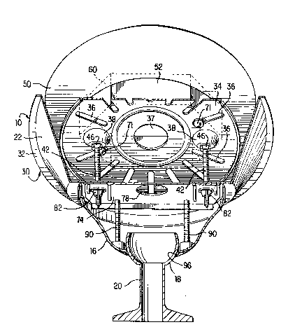
An adaptor assembly makes it possible to mount an electric
fixture, such as a ceiling fan or electric lighting fixture, to a
ceiling with a slope greater than 32. The adaptor assembly
includes a slope angle extension cover formed as a truncated
conical surface with a bottom end lying in a first plane adapted
for attachment to a standard fixture canopy and a top end lying in
a second plane at an angle of 26 to the first plane and adapted to
be attached through an adaptor mounting plate to a junction box
mounted in a recess in the ceiling.
The mounting plate has a plurality of radial slots and is
rotated to bring a pair of slots in alignment with screw holes in
mounting lugs on the junction box for attachment with screws. The
mounting plate has a pair of deformations providing flat wall
portions which, when the mounting plate is installed are in
parallel to the bottom end of the extension cover. A pair of
screws each extend through the flat wall portion of a deformation
and a screw hole provided through the bottom end of the cover to
mount the cover with the top end confronting and parallel to the
sloped ceiling. An insulation disk is sandwiched between the
mounting plate and the ceiling and is secured to the mounting plate
by a pair of adhesive tabs.


Claims

Note: Claims are shown in the official language in which they were submitted.


CLAIMS
1. An adaptor assembly for adapting an electric fixture for
mounting on a highly sloped ceiling, comprising:
a sloped angle extension cover formed as a truncated surface
having a bottom end adapted for attachment to a standard fixture
having a mounting canopy, said bottom end lying in a first plane,
and a top end lying in a second plane at an angle to said first
plane;
an adaptor mounting plate, smaller in extent than said top
end, said mounting plate having a pair of holes adapted to
receiving screw means for attaching said extension cover to said
mounting plate and a plurality of openings adapted to receive screw
means for attaching said mounting plate to a junction box mounted
in a recess in said ceiling with said mounting plate in
confrontation with said ceiling.
2. An adaptor assembly of claim 1, wherein said angle is 26
degrees.
3. An adaptor assembly of claim 1, wherein said bottom side
of said extension cover is adapted for attachment to said mounting
canopy of said standard fixture.
4. An adaptor assembly of claim 1, wherein said adaptor
mounting plate openings comprise a plurality of radial slots, said
radial slots being adapted to receive said screw means for

attaching said mounting plate to said junction box, whereby said
adaptor mounting plate may be easily adjusted to align a pair of
said slots with screw receiving holes provided through said
junction box.
5. An adaptor assembly of claim 4, wherein said adaptor
mounting plate has a pair of deformations each having a wall
portion parallel to said bottom end of said extension cover, each
of said holes being provided through said wall portion of one of
said deformations.
6. An adaptor assembly of claim 1, wherein said adaptor
mounting plate has a pair of deformations each having a wall
portion parallel to said bottom end of said extension cover, each
of said holes being provided through said wall portion of one of
said deformations.
7. An adaptor assembly of claim 1, wherein said top end of
said extension cover is oval and has an outer rim surrounding an
oval opening, said assembly further comprising an oval insulation
disk dimensioned to extend beyond said mouthing plate and fitting
within said rim, said insulation disk being in abutment with said
ceiling between said mounting plate and said ceiling when said
mounting plate is attached to said junction box in confrontation
with said ceiling.

8. An adaptor assembly of claim 7, wherein said mounting
plate is a disk.
9. An adaptor assembly of claim 7, wherein adhesive means
secures said insulation disk to said mounting plate.
10. An adaptor assembly of claim 9, wherein said adhesive
means comprises adhesive patches between said insulation disk and
said mounting plate.
11. An adaptor assembly of claim 1, wherein said extension
cover comprises a truncated conical wall extending between said
bottom end and said top end.
12. An adaptor mounting plate for mounting a slope angle
extension cover to a highly sloped ceiling, said extension cover
having a top end parallel to said mounting plate and a bottom end
at an angle to said top end, comprising;
a set of radial slots adapted to receive screw means for
attaching said mounting plate to a junction box mounted in a recess
in said ceiling, whereby the rotational position of said adaptor
mounting plate may be easily adjusted to align a pair of said slots
with screw receiving holes provided on said junction box; and
a pair of deformations each having a wall portion parallel to
said bottom end of said extension cover when said cover is mounted
on said mounting plate, holes being provided through said wall

portions of said deformations for receiving screw means for
attaching said extension cover to said mounting plate.
13. An adaptor mounting plate of claim 12, wherein said angle
is 26 degrees.
14. A slope angle extension cover, comprising:
a bottom end adapted for attachment to a standard fixture,
said bottom end lying a first plane;
a top end lying in a second plane at an angle to said first
plane; and
a truncated conical wall extending between said bottom and top
ends.
15. A slope angle extension cover of claim 14, wherein said
angle is 26 degrees.

Description

Note: Descriptions are shown in the official language in which they were submitted.


a ~D5~ 5~
SLOPED ~TTTNG ADAPTOR
- BACXGROUND OF THE lNV ~rJTION
1. FIELD OF THE lNV~N'l'lON
This invention relates to adaptors for adapting a ceiling fan
or light fixture mounting to highly sloped ceilings, and more
particularly, to ceilings with slopes in excess of 22 degrees.
2. DESCRIPTION O~ THE PRIOR ART
It is customary to mount ceiling fans and light fixtures on
sloped ceilings which do not exceed a 32 degree angle with the
horizontal. Such mountings comprise a standard mounting canopy
which is mounted to the ceiling by bolting the canopy to a crossbar
mounting bracket mounted on the ceiling beneath a junction box
installed in the ceiling. At its lower end, the standard canopy
provides a socket which cooperates with a ball to form a ball and
socket joint. The ball is formed on the top end of a shaft, on the
lower end of which the ceiling fan or lighting fixture is mounted.
Although the ball and socket joint provides satisfactory
accommodation to the slope of the ceiling when the slope does not
exceed 32 degrees with the horizontal, for slopes which exceed 32
degrees, the mounting is no longer satisfactory.

~ 1~5a5~
S~MMARY OF T~E lNV~. ,lON
It is accordingly the obj ect of ~e invention to provide an
adaptor to make ~t possible to ~unt a ceiling fan or lighting
fixture rom a ceiling with a ~lope which eYc~ed~ 3a degrees.
To this end, the invention aontemplates the pro~lsion o~ a
810pe angle extens~on cover formed as a truncat~d c~nical surface
haYing a bottom end lying in a ~ir6t plane and sdapted ~or
attachment to a ~t~n~ fixture, 6uch a~ a cell~ng $an or lighting
fixturc, ~nd a top end lying in a ~CQn~ ~lane at an angle of 26
to the ~irst plane and adapte~ for attach~ent to a ~unction ~oX
mounted ln a recess in the ceiling. In ordRr to mount the
extension cover from the iunction box, an adaptor mounting plate ls
provided. ~he mounting plate is a disk, ~hich i~ s~aller in extent
than th~ top end o$ the extension cover, and ~as a plurality of
radial 810ts. ~y ad~ustlng t~e rotatlonal positlon of t~e mountlng
plate, a pair o~ the radial ~lots may be aligned wlth scr~w hole~
on mounting lug~ provid~d on tho ~unction box; the ~lot8 and 6crew
holes then receive ~crews ~or attaching the mo~nting plate to the
junction b~x. To ~acllit~te mounting the extension cover on the
mounting plate, a pair Or de~ormations are pro~lded on opposlte
~$de~ of the mount~ng plate on a diametric line. The de~ormations
have 2 flat surface portion which 1~ parallel to th~ botto~ s~de o~
the extension cover. When the mounting plate ie attached to the
~unction box, the de~ormations are posit~oned at the sa~e height on
the ce~ling. Mounting screws are then posltloned t~rough aligned
holes provided in the bottom en~ of the extension cover and through

5 ~
the flat surface portion of a corresponding deformation.
When the adaptor mounting plate is attached to the junction
box, an insulation disk, which is larger than the mounting plate
but fits within the top end of the extension cover, is sandwiched
between the mounting plate and the ceiling, being attached to the
mounting plate by a pair of adhesive pads.
BRIEF DESCRIPTION OF THE DRAWINGS
A clearer understanding of the invention will be apparent from
the following description and drawings, wherein;
Fig. 1 is a perspective view showing a slope angle extension
cover of the invention mounting a standard fixture on a highly
sloped ceiling;
Fig. 2 is an exploded view showing a sloped ceiling adaptor of
the invention mounting a standard fixture to a highly sloped
ceiling;
Fig. 3 is a view, partially broken away and partially in
section, of the adaptor assembly of the invention mounted from a
junction box in the ceiling and supporting a standard fixture; and
Fig. 4 is a top view of the extension cover; and
Fig. 5 is a cross-section view showing a sloped ceiling
adaptor assembly of the invention mounting a standard fixture to a
highly sloped ceiling.

a sL~
DETAILED DESCRIPTION
Turning to Fig. 1, a sloped ceiling adaptor assembly of the
invention includes a ceiling adaptor cover 10 shown mounting a
standard fixture 12 to a highly sloped ceiling 14. The standard
fixture includes an inverted bell-shaped canopy 16 having a ball 18
of a ball and socket connection on a support rod 20 of a standard
fixture, such as a ceiling fan or an electric lighting fixture (not
shown).
As seen in Fig. 4, ceiling adaptor cover 10 has a truncated
conical wall 22 with a bottom end 24 having a flat wall 25 with a
central opening 26-and a pair of screw holes 27 and 28 on a common
diametric line which is perpendicular to the widest dimension of
the cover (the vertical as seen in Fig. 4). Cover 10 has an oval
top end 30 which is larger than bottom end 24 and includes an
outwardly extending narrow rim 32. The inner edge 33 of rim 32
defines a large opening at top end 30.
As seen in Fig. 2, an adaptor mounting plate 34 is in the form
of a metal disk having two sets of seven equally spaced radial
mounting slots 36 and a central circular opening 37 to accommodate
wiring to the fixture from a junction box 60 mounted in a recess 61
in the ceiling. Between each set of slots are a pair of
deformations 38 having a screw holes 39 located on common diametric
line of mounting plate 34. As seen in Fig. 5, each deformation 38
includes a flat wall portion 40, which, when mounting plate 34 is
mounted in confronting relation and parallel to ceiling 14, is
parallel to bottom end 24 of adaptor cover 10. A pair of screws

slt
42, only one of which is visible in Fig. 5, connect adaptor cover
10 to mounting plate 34. Each screw 42 extends through a screw
hole 39 through flat wall portion 40 of a corresponding deformation
38 and through a screw hole 27 or 28 through bottom end wall 25
(see Fig. 2). The screws are secured by flange nuts 46, and flat
washers 48 are used under the heads 43 of screws 42.
An oval insulated disk 50 is sandwiched between mounting plate
34 and ceiling 14 as seen in Fig. 5. Disk 50 is dimensioned to
just fit within rim 32 at top end 30 of adaptor cover 10. As seen
in Fig. 2, insulation disk 50 has a pair of arcuate openings 52 and
53 separated by ribs 54. Openings 52 and 53 are positioned to
overlie respective sets of slots 36. The disk also has a circular
opening 55 positioned in alignment with central opening 37 of
mounting plate 34. A pair of adhesive pads 56 and 57 are used to
secure insulation disk 50 to mounting plate 34.
The installation of the adaptor assembly of the invention will
be best understood from the exploded view of Fig. 2.
A flat washer 48 is placed on each screw 42 before it is
installed on adaptor plate 34. Each screw 42 is then extended
through a screw hole 39 in flat wall portion 40 of a deformation
38, while making sure that screw head 43 and washer 48 are seated
inside adaptor plate deformation 38. Flange nuts 46 are then
threaded onto screws 42 all the way down to wall 40 of mounting
plate 34 and are tightened securely.
In order to secure insulation disk 50 to mounting plate 34,
adhesive patches 56 and 57 are placed on each side of center hole

a ~a5~
55 in line with ribs 54. Insulation disk 50 is then positioned
with center hole 55 lined up with center hole 37 of mounting disk
34 and with ribs 54 over deformations 38 and firmly pressed to
attach disk 50 to plate 34.
Mounting plate 34 is then aligned with junction box 60 mounted
in recess 61 in ceiling 14 (see Fig. 5). Junction box 60 includes
mounting tabs 64 having screw holes 66. Mounting plate 34 is
rotated until a pair of slots 36 line up with junction box screw
holes 66. Although the ceiling adaptor of the invention works best
when mounting screws 42 are aligned horizontally, it may not be
possible, due to the type and structural details of junction box
60, to align screws 42 perfectly on the same horizontal line.
However, the adaptor of the invention is designed to work well in
situations in which screws 42 are as much as 20 out of alignment
with the horizonal. If there is misalignment, the greater the
deviation from the horizontal, the smaller is the slope angle that
can be reduced by the adaptor. After a pair of slots 36 are
aligned with junction box screw holes 66, screws 68 with flat
washers 70 positioned under screw heads 71 are extended through
slots 36 and threaded with screw holes 66 through junction box
mounting lugs 64. Since further adjustment may be necessary,
screws 68 should not be over tightened.
In order to verify that the point 72 of ceiling adaptor cover
(the point on rim 32 which is the greatest distance from bottom end
24) is pointed toward the peak of the room, ceiling adaptor 10 is
held with screw holes 27 and 28 slipped on screws 42. If adaptor

~1~5~
cover 10 does not so line up, it will be necessary to return to the
adaptor mounting plate rotation step to rotate mounting plate 34 to
bring another pair of slots in alignment with junction box mounting
holes 66.
If cover point 72 is pointed to the peak of the room, a
crosch~r mounting bracket 74, which is a conventional fan mounting
bracket, is slipped on screws 42. To facilitate this, bracket 74
has a pair of screw receiving slots 76 and 77 at opposite ends.
Bracket 74 also has a central wire receiving opening 78. A set of
wires (not shown) from junction box 60 are extended through opening
78 and are lengthened for this purpose if necessary. To secure
bracket 74 in place, wing nuts 82 are threaded onto screws 42
protruding through screw holes 27 and 28 in cover bottom wall 25
and through mounting bracket slots 76 and 77. The nuts are
tightened securely, but are not over tightened.
The next step is the installation of conventional inverted
bell-shaped canopy 16. Pursuant to the usual practice, canopy 16,
which has four screw holes 86, is rotated to bring screw holes 86
in alignment with a set of four screw holes 88 through bracket 74.
Screws 90, with lock washers 91 positioned under screw heads 92,
are then inserted through screw holes 86 and threaded with screw
holes 88. An opening 94 is provided in the side of canopy 16
pointing toward the ceiling peak. This provides means for feeding
out the wiring from junction box 60 for connection to the ceiling
fan or other electrical fixture supported by canopy 16.

- a ~
A socket 96 is provided at the b~ m end of canopy 84
surrounding central opening 98. Ball 18 at the top of fan, or
fixture, support rod 20 completes the ball and socket joint. It
will be understood that ball 18 will be engaged with socket 96 of
canopy 16, as shown in Figs. 1, 3 and 5, before connection of
canopy 16 to bracket 74.
With the adaptor assembly installed as described, the mounting
of the fan or lighting fixture is readily accommodated to a highly
sloped ceiling. To the angular adjustment provided by the ball and
socket joint of the conventional mounting, there is added the
additional angular-adjustment provided by the adaptor assembly.
Although the invention has been described with reference to a
particular embodiment, it is to be appreciated that various
adaptations and modifications maybe made within the spirit of the
invention.
The invention claimed is:

Representative Drawing
A single figure which represents the drawing illustrating the invention.
Administrative Status

2024-08-01:As part of the Next Generation Patents (NGP) transition, the Canadian Patents Database (CPD) now contains a more detailed Event History, which replicates the Event Log of our new back-office solution.

Please note that "Inactive:" events refers to events no longer in use in our new back-office solution.

For a clearer understanding of the status of the application/patent presented on this page, the site Disclaimer , as well as the definitions for Patent , Event History , Maintenance Fee  and Payment History  should be consulted.

Event History

Description Date
Application Not Reinstated by Deadline 2006-12-14
Time Limit for Reversal Expired 2006-12-14
Inactive: IPC from MCD 2006-03-12
Inactive: Abandoned - No reply to s.30(2) Rules requisition 2005-12-21
Inactive: Abandoned - No reply to s.29 Rules requisition 2005-12-21
Deemed Abandoned - Failure to Respond to Maintenance Fee Notice 2005-12-14
Inactive: S.29 Rules - Examiner requisition 2005-06-21
Inactive: S.30(2) Rules - Examiner requisition 2005-06-21
Amendment Received - Voluntary Amendment 2003-03-12
Letter Sent 2003-01-15
Inactive: Status info is complete as of Log entry date 2003-01-15
Inactive: Application prosecuted on TS as of Log entry date 2003-01-15
Request for Examination Requirements Determined Compliant 2002-12-12
All Requirements for Examination Determined Compliant 2002-12-12
Inactive: Entity size changed 2002-01-04
Application Published (Open to Public Inspection) 1996-06-16

Abandonment History

Abandonment Date Reason Reinstatement Date
2005-12-14

Maintenance Fee

The last payment was received on 2004-12-01

Note : If the full payment has not been received on or before the date indicated, a further fee may be required which may be one of the following

  • the reinstatement fee;
  • the late payment fee; or
  • additional fee to reverse deemed expiry.

Patent fees are adjusted on the 1st of January every year. The amounts above are the current amounts if received by December 31 of the current year.
Please refer to the CIPO Patent Fees web page to see all current fee amounts.

Fee History

Fee Type Anniversary Year Due Date Paid Date
MF (application, 2nd anniv.) - small 02 1997-12-15 1997-10-20
MF (application, 3rd anniv.) - small 03 1998-12-14 1998-08-12
MF (application, 4th anniv.) - small 04 1999-12-14 1999-12-08
MF (application, 5th anniv.) - small 05 2000-12-14 2000-12-01
MF (application, 6th anniv.) - standard 06 2001-12-14 2001-12-13
MF (application, 7th anniv.) - standard 07 2002-12-16 2002-12-11
Request for examination - standard 2002-12-12
MF (application, 8th anniv.) - standard 08 2003-12-15 2003-11-26
MF (application, 9th anniv.) - standard 09 2004-12-14 2004-12-01
Owners on Record

Note: Records showing the ownership history in alphabetical order.

Current Owners on Record
HUNTER FAN COMPANY
Past Owners on Record
CRAIG CHANDLER
JIM CUTHBERTSON
RAY CHIN
Past Owners that do not appear in the "Owners on Record" listing will appear in other documentation within the application.
Documents

To view selected files, please enter reCAPTCHA code :


To view images, click a link in the Document Description column. To download the documents, select one or more checkboxes in the first column and then click the "Download Selected in PDF format (Zip Archive)" or the "Download Selected as Single PDF" button.

List of published and non-published patent-specific documents on the CPD .

If you have any difficulty accessing content, you can call the Client Service Centre at 1-866-997-1936 or send them an e-mail at CIPO Client Service Centre.


Document
Description 
Date
(yyyy-mm-dd) 
Number of pages   Size of Image (KB) 
Representative drawing 1999-06-27 1 29
Abstract 1995-12-13 1 35
Description 1995-12-13 8 293
Drawings 1995-12-13 5 126
Claims 1995-12-13 4 115
Reminder of maintenance fee due 1997-08-16 1 111
Reminder - Request for Examination 2002-08-14 1 116
Acknowledgement of Request for Examination 2003-01-14 1 173
Courtesy - Abandonment Letter (Maintenance Fee) 2006-02-07 1 174
Courtesy - Abandonment Letter (R30(2)) 2006-02-28 1 166
Courtesy - Abandonment Letter (R29) 2006-02-28 1 166
Fees 2002-12-10 1 40
Correspondence 1996-01-24 2 92
Fees 2003-11-25 1 38