Note: Descriptions are shown in the official language in which they were submitted.
~1 65~LQ~
APPLICATION FOR PATENT
INVENTOR: Steven P. Klak
TITLE: Safety Guard For Orifice Fitting Device
FIELD OF THE INVENTION:
This invention relates in general to a dual chamber orifice fitting device having a removable
orifice plate for measuring fluid flow in a flow line, and particularly to a safety device that prevents
inadvertent actuation of a valve member separating the dual chambers by an operator.
BACKGROUND OF THE INVENTION:
Heretofore, dual chamber orifice fitting devices have been used for measuring the flow of
fluids through pipe while ~Itili7:in~ an orifice plate in the flow line. An orifice plate consists of a flat
plate with a predeterrnined opening therein. By measuring the pressure di~el enlial on opposite sides
of the orifice plate, the rate of fluid flow can be deterrnined in the pipeline.An orifice plate must be m~int~ined in relatively good condition to assure measurement
accuracy. The opening or bore of the plate must remain clean and its upstream edge must remain
sharp and free of nicks. Debris or foreign matter built up on the faces of the plate can also adversely
affect the accuracy of the flow measurement. Since the fluid flowing in pipelines may contain
substances or particulates which may adversely affect the orifice plate, it is desired that the plate be
periodically in~pecte~l In fact, it is common practice in the industry and even recommended that the
plate be inspected on a periodic basis, such as each month. This inspection involves removing the
orifice plate from the pipeline, inspecting it, and either rein~t~lling it in the pipeline or, should its
condition require, replacing the orifice plate. Also, in the event flow conditions change, such as an
increase or decrease in the fluid flow rate, an orifice plate with a larger or smaller opening or bore
may be required. This would require removing the old orifice plate and replacing it with a new one
with a di~relenl bore. In either of the aforementioned situations, it is necessary to provide a means
for the removal and imt~ tion of the orifice plate in the orifice fitting or flow measurement device.
It is desirable that the orifice plate be removed and replaced without ~hntting down the
pipeline so that flow through the pipeline is m~int~ined For this purpose, a dual chamber orifice
fitting device has been provided in which an inner or lower chamber is provided in continuous fluid
communication with the flow line while an outer or upper chamber is isolated for removal of the
orifice plate. A valve member or isolation member is positioned between the chambers and when
closed to separate the chambers, the outer chamber may be exposed to atmosphere. However, the
216~0~
-
5 lower chamber does not have to be reduced to atmospheric conditions to remove the orifice plate
from the pipeline. Thus, the flow of fluid does not have to be stopped.
One ofthe most common designs for a dual cha~ el orifice fitting device is a "Senior Orifice
Fitting" m~mlf~c~lred and sold by Daniel Industries, Inc. of Houston, Texas and described in Catalog
100A, entitled "Senior Orifice Fitting Technical Manual", published by Daniel Industries, Inc. This
design is also disclosed in U.S. Patent Nos. 1,996,192 and 2,688,987, which are incorporated by this
reference.
In most dual chamber orifice fitting devices, an operator must rotate at least two, and possibly
three, shafts to effect removal and replacement of an orifice plate. The shafts, in turn, rotate gears
that provide a means for raising or lowering the orifice plate between the chambers, or a means for
opening and closing an isolation valve between the chambers that will isolate the upper chamber from
line pressure. In addition to rotating these shafts, the operator must rotate other devices, such as a
bleed valve that can reduce the internal pressure of the outer chamber to atmospheric conditions, a
valve that can equalize the pressure between the upper and lower chambers, or bolting to open the
upper chamber. Thus, many steps are involved in the removal and inst~ tion of an orifice plate.
To f~ it~te the process, some manufacturers have standardized on the wrench required to operate
the shafts, valves, and bolting. An operator may use the same wrench in each of these steps while
moving the same wrench from various shafts, valves, and bolts, or the operator may choose to use
more than one wrench, but in all situations there are many steps required to remove and install an
orifice plate and an operator must turn a number of items in the proper sequence.
The relatively large number of steps to remove and install an orifice plate can be confusing
to an operator. To assist the operator in operating the device, m~nllf~cturers place instruction plates
on the orifice fitting devices to help guide the operator through the procedure in the proper sequence.
However, due to paint or a build up of foreign matter on the instruction plate, or through natural
weathering, the instruction plate is often difficult or impossible to read. In addition, instruction
plates, name plates and the like, are often removed from valves and orifice fitting devices prior to
painting and are not always repositioned after the p~inting Thus, the operator operating the orifice
fitting device is often without instructions readily available, a circumstance that can add to a possibly
confusing situation. Even if the instruction plate is present and readable, an operator may not read
it as each step is performed due to the familiarity of the operator with the procedure. An operator
may also momentarily forget the proper sequence of steps or become confused. In addition, most
manufacturers standardize on a common side of the orifice fitting device on which the shafts are
exposed for operation. Sometimes the operating shafts are located on a side other than the normal
~l6s~n~
S side to facilitate the positioning of an orifice fitting device within a limited space. This alternate
placement of the operating shafts requires that the shafts be rotated difrerel"ly with regard to
previously known procedures and this can also cause confusion.
In all of the above mentioned designs or orifice fitting devices, a dangerous condition may
occur when the internal pressure of the upper chamber is reduced to atmospheric conditions and the
10 upper chamber itselfis opened for removal ofthe orifice plate. When this condition occurs, the valve
or device that isolates or separates the upper and lower chambers is the only member that prevents
the line pressure from rapidly e~h~usting through the outer opening of the upper chamber. The
operator operating the orifice fitting device must be careful not to open the isolation valve between
the inner and outer chambers. If the isolation valve is opened when the upper chamber is opened to
15 atmosphere, highly pressurized fluid from the main flow line will rapidly vent through the rather large
opening between the upper and lower chambers and out through the upper opening of the upper
chamber into the atmosphere. Obviously, this is not a safe condition for the operator operating the
orifice fitting device as the operator is usually in very close proximity to the opening to atmosphere.
Further, when rein~t~lling an orifice plate in many designs of the orifice fitting device, a relatively
20 large metal plate or carrier for the circular orifice plate is placed within the upper chamber. An
operator must proceed with a number of steps to close the upper chamber, isolate the upper chamber
from atmosphere, and repressurize the upper chamber. However, as mentioned before, the operator
may become confused and forget to take the steps in sequence and may inadvertently open the
isolation valve between the cl-a~-~el s before isolating the upper chamber from atmosphere. As soon
25 as the isolation valve between the chambers is opened, the rapidly escaping pressurized fluid rapidly
forces any unsecured member, such as a carrier device, out ofthe upper chamber resulting in possible
damage to property or injury to personnel.
Because of the complexity of operating such a dual chamber orifice fitting device and the
resulting possibility that an operator may perform an operating step out of the proper sequence,
30 particularly opening the isolation valve between the dual chambers out of sequence, there is a need
for a safety device or interlock that will effectively prevent an operator from m~nll~lly opening an
isolation valve between the dual chambers when a pressure di~l ~ ial exists in the two chambers.
SUMMARY OF THE INVENTION:
The present invention discloses a safety guard device for a dual chamber orifice fitting device
3 5 to prevent the opening of an isolation valve between the dual chambers when a pressure di~l ~nlia
exists between the chambers. The orifice fitting device includes a shaft for actu~ting the isolation
valve member between the chambers and an end of the shaft extends externally of the housing or
4 0 4
5 body ofthe orifice fitting device. A tool connector on the end ofthe shaft is m~nll~lly engaged by
a tool such as a wrench. The safety guard device includes a fluid pressure responsive member that
is movable to a position for blocking access to the external tool connector, such as a square tool
fitting on the end of the shaft, when a fluid pressure di~elenlial exists in the dual chambers, and
movable to a position for pellni~ g access to the external tool connector to permit actuation of the
10 valve member between the chambers when the fluid pressure in the fluid chambers is equalized.
The fluid pressure responsive member includes an end guard or sleeve mounted for movement
to an ~xt~n~led covered position ofthe tool connector on the end ofthe shaft when a fluid di~renlial
exists between the chambers to prevent a tool fitting on the tool connector in the extended covered
position. When the fluid pressure between the chambers is equalized, the sleeve is retracted from
15 the tool connector to uncover the tool connector to permit an operator to place a tool on the tool
connector for rotation of the shaft. As mentioned previously, only when the two fluid chambers are
of equal pressure should the isolation valve between the fluid chambers be operated. When the upper
chamber is of a lesser pressure than the lower chamber, the fluid chamber in the lower chamber is
effective to move the sleeve over the tool connector on the external end of the shaft to prevent access
20 to the shaft by a wrench or any other means. By doing so, the isolation valve cannot be opened,
intentionally or otherwise, thereby elimin~ting a possible dangerous situation. Once the upper and
lower chambers are returned to equal pressure, as when the orifice plate is reinstalled in the orifice
fitting device and the upper chamber is closed to atmosphere, the sleeve over the tool connector on
the end of the shaft is retracted to allow wrench access to the shaft. The fluid connection to the
25 upper chamber pressure is through an external tubing connected between the safety guard and a tee
connection located between a bleed valve and the upper chamber. Opening the bleed valve to reduce
the internal pressure of the upper chamber activates the fluid pressure responsive member of the
safety guard device forcing it out over the end of the operating shaft.
As an added feature, a spring continuously urges the fluid pressure responsive member to a
30 retracted position so that the sleeve or guard is retracted when there is no pressure in the orifice
fitting device, such as when the orifice fitting device is not in service. This allows an operator to
operate the isolation valve prior to in~t~ tion. An inspector may also check the functioning of the
orifice fitting device prior to pressuring or in~t~lling the orifice fitting device in a pipeline.
The safety guard device of the present invention is designed to be readily installed on a new
35 orifice fitting device, or as a retrofit on existing orifice fitting devices in service in the field. The
orifice fitting devices already in service in the field are easily retrofitted by isolating an orifice fitting
device from line pressure and in~t~lling the safety guard device.
2~65~04
BRIEF DESCRIPTION OF Tl~E DRAWINGS:
Figure 1 is a lon~ 1in~l sectional view of a typical dual chamber orifice fitting device having
a removable orifice plate;
Figure 2 is a front elevation of the orifice fitting device shown in Figure 1;
Figure 3 is a cross sectional view of the safety guard device of the present invention with the
guard or sleeve in a retracted position in which fluid pressure in the dual chambers is equalized;
Figure 4 is a cross sectional view of the safety guard device shown in Figure 3 in which fluid
pressure in the dual chambers is not equal with the guard or sleeve in an extended position over the
tool connector of the shaft to prevent tool access to the tool connector; and
Figure 5 is an end view of the safety guard device shown in Figures 3 and 4.
DETAILED DESCRIPTION OF THE INVENTION:
Referring now to the drawings for a better underst~nl1ing of this invention, Figure 1 shows
a cross section of a typical dual ch~llbel flow measuring or orifice fitting device desi~n~ted generally
at 1. Orifice fitting device 1 is connected to a pipeline that transports fluids, such as natural gas, at
weld bevel 2 at one end and flange 3 at an opposed end. The normal direction of fluid flow is
indicated by the arrow shown in Figure 1, but fluid may flow in the opposite direction. The dual
chamber orifice fitting device 1 has a body 6 defining a lower chamber 9 and a bonnet 70 secured to
body 6 and defining an upper chamber 8. In this normal operation, an orifice plate 4 is located in the
fluid flow path 5 and is held in place by a plate carrier 7 and positioning equipment (not shown) in
body 6. As fluid flows through orifice plate bore 10, a pressure di~erenlial develops and is sensed
by externally mounted, speci~li7ed pressure measuring equipment through holes 11 and 12. Also,
while in the normal operation, a slide valve carrier 13 abuts a stop pin 14 so that a valve member 16
for sepa~ g or isolating chambers 8 and 9 is properly centered over a rect~n~ r slot in valve seat
17. Valve ll,~."I)e 16 is consla"lly urged against seat 17 by a plurality of springs 15 and defines an
isolation valve between chambers 8 and 9. When required, valve carrier 13, valve member 16, and
springs 15 can be moved to the right by rotating a valve gear shaft 18 until slide valve carrier 13
contacts the inside wall of lower chamber 9 at 19. When in this position, valve carrier 13 and valve
",en~er 16 are completely clear ofthe rect~n~-l~r slot in valve seat 17. This positioning is required
to allow orifice plate 4 and plate carrier 7 to pass through the rect~ng~ r slot in valve seat 17. The
sequence required to accomplish this will be set forth hereinafter.
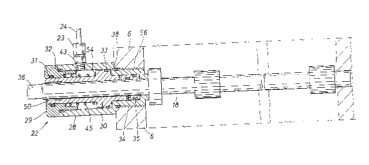
Referring now to Figure 2, the safety guard or lockout device, generally referred to as 22,
is mounted externally on body 6 ~dj~cent lower chamber 9 to prevent inadvertent actuation of valve
member 16. Valve gear shaft 18 extends through body 6. A tubing connector 23 is fastened to
2165~0~
safety guard device 22. Tubing 24 is connected at its lower end to tubing connector 23 to provide
a pressure tight connection between safety device 22 and a tee connection 26 on bonnet 70 adjacçnt
upper chamber 8 as shown in Figure 1. The other upper end of tubing 24 is connected to tubing
connector 25 on tee connection 26. An end of tee connection 26 has a bleed valve 27 secured
thereto. The other end of tee connection 26 is secured externally to bonnet 70 ~djac~nt upper
chamber 8.
Referring to Figure 1, when it becomes n~ceSs~ry to remove orifice plate 4 from orifice fitting
device 1 for inspection or replacement, an equalizer valve stem 20 is rotated counterclockwise to
allow the fluid pressure in lower chamber 9 and upper chamber 8 to be equalized. When this occurs,
the safety guard device 22 is act~l~ted Referring to Figure 3, the safety guard device 22 includes a
body 28, an end plug 29, a spring 45, and O-rings 31, 32, 33, 34, and 35. A fluid responsive piston
Illell.l~el 30 is mollnted within body 28 about valve gear shaft 18 for movement between a retracted
position shown in Figure 3 and an extended position shown in Figure 4. Valve gear shaft 18 has a
square end 36 defining flats which form a tool connector for engagement by a suitable manual tool,
such as a wrench, to rotate gear shaft 18 for movement of valve member 16 between opened and
closed positions relative to chambers 8 and 9. Piston member 30 includes an outer guard or end
sleeve 50 which is adapted to fit over square end 36 in an extended position as shown in Figure 4.
Piston member 30 has an inner end 52 opposite guard 50 which is exposed to fluid pressure from
chamber 9. An annular shoulder 54 on piston member 30 is exposed to fluid pressure from upper
chal--l)el 8 through tubing 24 as shown particularly in Figure 3. End plug 29 is threaded within body
28 about outer guard or sleeve 50. Spring 45 urges guard 50 and piston member 30 to a retracted
position as shown in Figure 3. O-rings 34 and 35 provide a fluid pressure area at areas A1 and A2
~dj~c~nt end 52 of piston member 30 which is in fluid communication with lower chamber 9 by fluid
leakage from chamber 9 past body 28 and gear shaft 18. A suitable opening, if desired, may be
provided for leakage from chamber 9 to piston member 30. Body 28 of safety guard device 22 has
an externally threaded inner end at 56 which is threaded within internally threaded openings 57 to
body 6 of orifice fitting device 1 as indicated in Figures 3 and 4. O-ring 35 seals between piston
member 30 and body 28. O-ring 34 seals between piston member 30 and gear shaft 18. O-rings 31
and 33 provide a fluid pressure area at areas A3 and A4 of piston member 30 which is in fluid
commlln:-~tion with upper chamber 8. O-ring 31 seals between guard 30 and end plug 29. O-ring
32 seals between end plug 29 and body 28. O-ring 33 seals between guard 30 and body 28. The
fluid pressure area at areas A3 and A4 is greater than the fluid pressure area at areas A1 and A2 to
provide a fluid pressure di~erellLial acting on piston member 30 when the pressure is equal in
21~0-i~
chambers 8 and 9.
End guard or sleeve 50 may be retracted away from the end of valve gear shaft 18 which
defines square end 36 thereon. Alternately, guard 50 may be extended out over square end 36 of
valve shaft 18 preventing a wrench to be connected to square end 36 thus making valve gear shaft
18 inaccessible and preventing manual operation of valve member 16. As shown in Figure 5, the
close plO~ y ofthe outer surface of valve gear shaft 18 and square end 36 to the inner surface of
guard 50 prevents affixing of a wrench to valve gear shaft 18.
As previously stated, the first step in removing orifice plate 4 is to equalize the pressure
between lower chamber 9 and upper chamber 8. The area defined by A4 minus A3 exposed to fluid
pressure from chamber 8 is greater than the area defined by A2 minus A1 exposed to fluid pressure
from cl~5."~1.er 9 thereby to urge piston member 30 to a retracted position shown in Figure 3. Spring
45 also continuously urges piston member 30 to a retracted position in which piston member 30
abuts body 28 at shoulder or abutment 38. In this position, guard 30 is in a retracted position and
allows a wrench or other tool to be connected to square end 36 of gear shaft 18 for movement of
valve member 16 to an open position.
Valve carrier 13 is moved to the right until it abuts lower chamber wall 19. The orifice plate
4 and carrier 7 can then be raised into chamber 8 by rotating gear shafts 21 and 37 until plate carrier
7 contacts an upper gasket 46 as shown in Figure 1. Valve gear shaft 18 is then rotated in an
opposite direction so that valve carrier 13 is moved to the left until it again abuts stop pin 14. In this
position, valve member 16 is in closed position against seat 17 to separate lower chamber 9 and
upper chamber 8. Equalizer valve stem 20 is then rotated clockwise to complete the pressure
isolation of lower chamber 9 and upper chamber 8. Bleed valve stem 42 of bleed valve 27 is rotated
counterclockwise to allow the pressure in upper chamber 8 to be reduced to atmosphere.
Now referring to Figure 4, when the pressure in upper chamber 8 is at atmosphere, the higher
pressure in lower chamber 9 acts against end 52 of piston member 30 between O-rings 34 and 35 to
urge guard or sleeve 50 outwardly overcoming the force of spring 45 until shoulder 54 on piston
member 30 abuts shoulder or abutment 43 on end plug 29. In this position, guard 50 is extended
over the square end 36 of valve shaft 18 and prevents a manual tool from being connected to end 36.
Thus, valve gear shaft 18 cannot be actl~ted and valve 16 remains in a closed position. As shown
in Figure 5, the close ploxilllily ofthe outer surfaces of valve gear shaft 18 and square end 36 to the
inner surface of guard 50 prevents connection of a tool to valve gear shaft 18. Referring to Figure
1, to complete removal of orifice plate 4, clamping bar screws 41 are loosened for the removal of
outer clamping bar 40, sealing bar 39, and gasket 46. Then, gear shaft 37 is rotated for upward
~1654~
~ .
movement of orifice plate 4 and plate carrier 7 for removal from the top of upper chamber 8. Piston
member 30 has an exhaust opening 75 extending to shaft 18 to permit fluid leakage for preventing
pressure lock of piston member 30.
To reinstall orifice plate 4, orifice plate 4 and plate carrier 7 are inserted within the upper end
of upper chamber 8. Gear shaft 37 is then rotated to move the plate carrier assembly dowllw~dly
completely within upper chamber 8. Upper gasket 46, sealing bar 39 and clamping bar 40 are
assembled onto orifice fitting device 1. Clamping bar screws 41 are then tightened. Bleed valve stem
42 is rotated clockwise, isolating chamber 8 from atmosphere. Equalizer stem 20 is then rotated
counterclockwise equalizing the pressure between the lower chamber 9 and upper chamber 8. Upon
equ~ ~ of the pressure in chambers 8 and 9, the di~e~ ial pressure area and spring 45 acting on
piston member 30 moves piston member 30 to the retracted position of Figure 3 until piston member
30 abuts shoulder 38 of body 30. In this position guard 50 is in a retracted position that allows a
wrench or other manual tool to be connected to square end 36 of valve gear shaft 18 for movement
of valve member 16 to an open position between chambers 8 and 9. Referring to Figure 1, an
operator can continue in~t~lling orifice plate 4 by rotating valve gear shaft 18 until valve carrier 13
once again abuts lower chamber wall 19. Gear shafts 37 and 21 are rotated to lower plate carrier
7 into its resting position in lower chamber 9. Valve gear shaft 18 is then rotated to move valve
carrier 13 to a position abutting stop pin 14. For further details of the operation of orifice fitting
device 1, reference is made to U.S. Patent Nos. 1,996,192 and 2,688,987, which are incorporated
herein by this reference.
Referring to Figure 1, prior to in~t~lling orifice fitting device 1 in a pipeline, or when the
pipeline is not pressurized and is at atmospheric conditions, there may be a desire to rotate valve gear
shaft 18 for opening or closing valve member 16. Since the entire pipeline is at equal atmospheric
pressure, guard 50 is not urged in any direction by fluid pressure. Spring 45 is the only force acting
on guard 50 and urges guard 50 to a retracted position as shown in Figure 3. This permits actuation
of valve member 16 as it may be desirable to operate valve member 16 to test its functionality prior
to starting up or pressurizing a pipeline, or to properly position valve member 16. Once pressure is
applied to the pipeline, safety guard device 22 will operate as previously described.
When pressure is applied to orifice fitting device 1, the forces generated by the pressure
acting on the di~erenlial fluid pressure area defined by the O-rings is much greater than the force
generated by spring 45. It may be desirable in some instances to delete the spring. Then, guard 50
may be m~nu~lly retracted if it is desired to operate the orifice fitting device without any pressure
in the orifice fitting device or pipeline. Manually retracting guard 50 could be accomplished by
2~L654~4
simply pushing on the exposed end of guard 50 to uncover square end 36 so that a suitable tool may
be connected thereto. Safety guard device 22 thus forms a lockout to prevent inadvertent actuation
of valve member 16.
Safety guard device 22 may be utilized as a retrofit unit and installed when the orifice fitting
device and the associated flow line are out of service. For in~t~ tion of safety guard device 22, an
externally threaded nut (not shown) about shaft 18 is unthreaded from internally threaded opening
57 in body 6 for removal of gear shaft 18 having square end 36 thereon. After the externally
threaded nut is removed from internally threaded opening 57, gear shaft 18 may be removed and
inspected for any possible damage. Gear shaft 18 may be reinserted or a new gear shaft 18 may be
provided if needed. Upon reinsertion of gear shaft 18, safety guard device 22 is positioned about
gear shaft 18 and externally threaded end 56 is threaded within internally threaded opening 57. Bleed
valve 27 is removed from bonnet 70 and threaded into tee 26 which, in turn is threaded into bonnet
70. Tubing connectors 23,25 and tubing 24 are then connected between safety guard device 22 and
tee connection 26. Upon imt~ tion of safety guard device 22, orifice fitting device 1 is placed in
service and pressurized.
While the present invention has been shown and described in its preferred embodiment, those
skilled in the art will recognize from the foregoing discussion that various changes, modifications,
and variations may be made thereto without departing from the spirit and scope of the invention as
set forth in the claims. In addition, it is to be understood that the above details given are to be
interpreted as illustrative and not in a limiting sense.