Note: Descriptions are shown in the official language in which they were submitted.
wo 95/00808 216 5 5 ~1 PCT/US94/07016
APPARATUS, PROCESS AND SYSTEM FOR
TUBE AND WHIP ROD HEAT EXCHANGER
R-rL~ und of the In~ention
This invention relates in general to heat transfer apparatus and
methods for evaporating, ~lictilling, freezing, he~ting or cooling liquids, and more
specifically, to an orbital drive for a whip rod used in conjunction with a tube and
~u-loullding shell type of heat eYch~nger.
When proceccing fluids, it is often required to transfer heat to or
from the liquid using a heat ~Y~h~nee surface, typically one formed of sheet
metal, and a second process fluid on the opposite side of the sheet metal that is at
a different temperature than the liquid being processed. This heat l-~--srer
between fluids may serve to warm the process fluid or cool it, as in a glycol chiller
commonly used in building air conditioning systems. It may also serve to change
the phase of the fluid, as in the production of fresh water by boiling it from sea
water, or the production of ice slurries by partially freezing water or a water
solution. Ice slurries are useful, among other applic~tionc~ for cold storage toreduce peak load power demands in building air conditioning systems and to
provide refrigeration for food such as milk stored on a dairy farm for transport to
a procec.cing plalit and fish catches stored on fishing vessels.
TLe size, and hence cost, of a heat eYrh~nger depends on the heat
transfer coefficient, which reflects resict~nce to heat flow through a layer of a
"hot" fluid, a heat ~Y~h~nger wall separating the hot and cold fluids, a layer of a
"cold" fluid, plus deposits fo-.ni..g on either hot or cold surfaces of the wall. For
econo,..ic reasons, a subst~nti~l temperature gradient is required to drive the heat
216~661
WO 95/00808 PCT/US94/07016
transfer through these resistances. This high gradient limits the energy efficiency
of evaporators or freezers by either limiting the number of stages or imposing ahigher lift on a vapor colllplessor
U.S. Patent Nos. 4,230,S29 and 4,441,963 issued to one of the
present applicants disclose a new approach to solving these problerns. They
involve using a vertical, thin-walled, open-ended heat transfer tube (or tubes)
driven in an orbital or wobbling motion. This orbital tube motion increases the
heat llal~rer efficiency by re~n-~ing the thermal resict~n~e at the inner and outer
surfaces of the tube. The motion swirls a liquid to be evapolated into a generally
thin film over the inner surface of the tube. This increases the evaporation
surface area and decreases the thermal resict~nce by decreasing the thickness ofthe liquid layer. The orbital motion also aids in heat transfer into the tube at its
outer surface produced by con(len~tion of a heated vapor stream. The
condensation increases the thickness of the liquid layer at the outer surface, and
hence its thermal res;~ e The orbital motion throws off the droplets, thereby
incleasing the heat transfer at the outer wall.
Both of these patents teach multiple such tubes held in a
conl~;nPr. Fccçntrics drive the tubes to undergo a wobbling motion in a
ho,i,olllal plane. The liquid is driven in turn by a dynarnic coupling to revolve
over the inner surface as it flows down the tube under the infllJence of gravity.
These all;~..ge~ nt~ require cranks, bearings and complicated seals inside the
e~a~ol~tor that ~ccommodate this movement. The component parts are difficult
and costly to ",~ ,f~cture and ~çmhle, they must be m~chinP-l to close
tolerances, they are susceptible to corrosion and co..t~...;..~l;on when used in the
chemical industry, and they wear, which leads to a deterioration in the balance of
the wobbling tubes and attendant vibrations. The '529 patent also discloses a self
-- 2 --
2165661
WO 95/00808 PCT/US94/07016
b~l~nring arr~ngement with a self adjusting orbital radius that accommodates thebalance to changes in mass. However, if the base moves, e.g., if the apparatus is
mounted on a moving reference frame such as a ship at sea, the crank radius mustbe fixed, and even this step may not be adequate.
Many known heat ~ er devices ranging from ice cream makers to
sophicti~te-l ~;v~ol~tors use a rigid wiper bar that is positively driven to rotate
within the tube to spread viscous liquids into a thin, evenly distributed film.
Posilively driven wipers can handle fluids with a viscosity of 1,000,000 c.p. orhigher. (Water has a viscosity of 1 c.p.) However, known heat transfer devices
using rigid, positively driven wiper or scraper have drawbacks. First there is aneed to introduce into the evaporator or freezer, and to seal, a rotational drive
shaft. Sec~n~l, ber~-lce the wiper or scraper is rigid and moving over a fixed
surface at close sp~cingC~ ..r~ ring and assembly become difficult and costly.
The surface must be m~hine(l to close tolerances, as well as the wiper/scraper
and its su~ oll structures. Further, these known rigid wiper a,lallgelllents aresusceptible to, and comr~ratively intolerant of, wear.
To solve these problems for less viscous fluids, e.g. those with a
viscosity of 1 to 1,000 c.p., U.S. Patent No. 4,618,399 describes a whip rod located
in the tube which spreads the feed liquid into a highly thin and Illli~llll film to
reduce its thermal res ~ ce and to enh~n~e its evaporation. The whip rod also
controls the build up of solid residue of evaporation. The '399 patent disclosesseveral alla~elllents for mounting the rod, incllltling lengths of cables, a flexible,
but non-rotating anchor conn~cted between a base and the lower end of the rod,
and a double universal joint also c~nnected between the lower end of the whip
rod and the base. While the whip rod is effective as a film distributor, the
m.~ g a~ gelllents have disadvantages. They increase the overall material,
2165G6 ~
WO 95/00808 PCT/US94/07016
~ccernhly and opcl~lillg costs. Also, they fail. Material fatigue of flexible cables
supporting the whip rods is a particular concern.
; .i~
U.S. Patent No. 4,762,592 describes an orbital drive that ovcrcollles
the .~-~....f~ctllre, ~ccemhly, wear and balance problems of the earlier eccentric-
crank drives. This hllproved drive uses a rotating counterweight or weights
mounted on the cv~olator and a spring-loaded strut su~ellsion for the
cvapolator. The counterweights and the mass of the evaporator revolve around
one another as the counterweights rotate.
While this arrangement does overcollle the problems associated with
an cccellllic crank drive, it also suffers from certain deficiencies. For example, it
requires the orbital movement of a large mass, particularly where the unit is
scaled up to a commercial size with multiple large tubes, each carrying a liquidstream. This mass increases the power requirements (particularly on start up),
increases the ~em~nrlc on the spring-strut suspension, can lead to an early fatigue
failure of the sllcpencion, and generally increases the construction and operation
cost of the system. It also increases the desirability of a stable operating platform,
e.g. a concrete floor, as opposed to one that moves such as a ship at sea or some
other transport. While the '592 patent proposes a solution to the moving platform
problem, the solution in practice has not been adequate when the ~alus has
been scaled up to commercially useful sizes. One problem was that when the unit
was scaled to a commercially acceptable size, motion of the base placed
m~^ceptably high loads on a crank or cranks that drove the entire unit into an
orbital motion.
While the orbital tube approach has been used for evaporation and
~lictill~tion, in the prior art it has not been applied for freezing. One reason is
216566 1
WO 9~/00808 PCT/US94/07016
that the liquid freezes to the heat transfer surface, increases the resistance to a
heat flow through the eY~h~nger, and thereby greatly reduces any performance
advantages of the orbital tube approach.
Currently, there are two principal types of cold storage systems on
the market using ice. One is known as the ice harvester type, where a group of
ice m~king m~rhines are inct~lled over an open storage tank. Ice grows to a
certain thirknesc before being periodically harv-ested into the tank by a derloslil,g
cycle. The other one is known as the ice bank type. It employs a group of low
cost heat llal~rer units, usually made of plastic, on which all the ice needed for
cold storage ~C~lmul~tec co"linuously during each chilling cycle. In either of
these two types, the effectiveness of transferring the heat from the water to the
refrigerant during the ice forming process is not as efficient as desired, thus
increasing equipment cost.
The concept of m~king ice in slurry form so that the ice m~king
m~-hine can operate co..L;..-~ously, without interruption, and with some hll~roved
heat transfer property has been attempted in the industry by comp~nies such as
the Chicago Bridge and Iron, Inc. and more recently, by the Electric Power
Research Institute ("EPRI") with their scheme publicized under the rade
deci~tion "Slippery Ice". At the present time the pel~"~a~,ce of the Slippery
Ice cold storage system is believed to be in the evaluation stage.
The EPRI sponsored research to develop a "Slippery Ice" system was
reported in an article entitled "Cool Storage: Saving Money and Energy" published
in the July/August 1992 issue of the EPRI Journal. In the EPRI s-~heme, calcium
ma~neCium ~cet~te is added to the water. According to EPRI, the use of this
additive causes ice to form in the liquid pool, away from the heat eY~h~..ger
-- 5 --
216S6~ ~
WO 95/00808 PCTIUS94/07016
surface, and results in a slushy type of substance that does not cling to metal. The
advantages of the "Slippery Ice" for hll~,rovillg the economy were also reported in
September 27, 1992 edition of The New York Times entitled "Keeping Buildings
Cool With Greater Efficiency". In this article the use of automobile antifreeze in
the water to be frozen was reported to be un~ti~f~ctory because it tends to lower
the freezing point too much.
The Slippery-Ice concept is attractive because it causes an ice slurry
to flow down a chilling surface under the infl~lence of gravity only, without
merh~nical aid. While Slippery Ice works, how it works is not known. Moreover,
this approach has several significant drawbacks. First, only one known additive
lets ice overcol~le the initial stickiness barrier to a gravity feed of crystals down
the chilling surface. This is of particular concern where the liquid being
proces~ed is a food product; this additive cannot be used. Another limitation isthat the heat fluY wetting rate and additive concentration must be carefully
controlled for the Slippery Ice to form. Also, the heat tl~,ls~er surface must be
elc~l opoli~he~l
In many cir~ nces, it is undesirable to require that the liquid
pass through the heat eY~h~n~er in a falling film. If the heat exchanger tubes
were flooded, then the liquid supply pres~u~e would be sufficient to transfer it to
the next proces~ing step. The complication and expense of an additional pump
and level control system, which are usually required in systems using a falling film
heat eY~ ger, would not be necessary. Heretofore orbital heat eYch~ngers have
been limited to operation with a falling film. One reason is that ber~ e the
entire appalatus orbits, or the tubes within the outer shell orbit, flooding thetubes greatly increases the mass being orbited. This in turn increases the powerrequired for operation, increases wear, and increases vibration/balance problems.
216~ifi~1
WO 95/00808 PCT/US94/07016
In addition, movement of whip rods within flooded tubes is, in general, impeded
by the liquid, or moves in coordination with the revolving body of liquid in thetube so that the rod has a (liminiched effect on the heat transfer process.
In certain applications it may be desirable to orient the heat
eYrh~nger tubes other than vertically. For example, on a ship, the pitch and roll
of the ship with the waves would require expensive gimbal arrangements to
operate with the tubes in a vertical orientation. Even in land-based systems, non-
vertical orie~t~tionc may be desirable to accommodate restrictions on equipment
height, to fit through doors or under existing ceilingc, and to ship units in standard
shipping co~ ;. .ers.
It is also desirable to reduce the vibration produced by unb~l~nced
ro~~ g or revolving masses (e.g. whip rods and drive members). The vibration is
easily seen by the user and raises concerns about equipment durability and
possible fatigue failure of pipe connections to the heat eY~h~nger. It also
increases the power CQ~ ...e'l and places an increased stress on the moul,lhlg
all~ngelllent. Heretofore, one solution has been to orbit tubes in groups with a180 phase difference between the groups. The '529 and '963 patents illustrate
this approach. The '592 patent lic~loses orbiting counterweights.
Recent development work suggests that as the orbital heat eY~h~nge
units are scaled up to more commercially useful sizes and operated under
c~n~litionc that ~ Xillli~e the heat transfer flux, a new set of design problemscome to the forcrrollt. Using orbital tec~mology, a straighlrolward way to scale up
at the desired surface-to-volume ratio is to use more tubes. For example, a
twenty ton freezer/chiller can have forty-two 1 1/2 inch diameter tubes. A thirty
ton e~al)ol~tor of the vapor col~ ression type for sea water des~lini7~tion can
21~5~61
WO 95/00808 PCT/US94/07016
have two hundred fifty-eight tubes. With this many tubes, significant problems
occur in delivering the required torque to all the tubes with the correct phase
relationship, providing manageable wear, keeping vibration low, part count low,
and providing assembly ease become roadblocks to commercially-sized multi-tube
~paralus.
Known orbital drives and co,lve;"tional wiper arrangements do not
meet demands of such multiple tube set-ups. The masses of the tubes, or
co"lai"ers and tubes, place extreme strains on rotary bearings of eccentrics
coupled between a rotary power source and the end application of the force.
Large forces quickly produce wear in bearings and at drive surfaces c~llcin~ play
in the drive train and a loss of the desired phase relationships between the
movement of groups of tubes. Large forces also increase the friction in the drive
train. To crank rods at each of many tubes using an array of gears or pulleys,
even without conci~çring wear, presents a ~ -n~ mec~nical design problem,
particularly if this mech~nical array is exposed to, or must be compatible with a
feed fluid. The wear problems, even in known wiper systems such as the
freezer/chiller sold by Sunwell using rolali"g wiper blades acting on a heat
eY~h~nee surface requires initial precise tolerancing and thereafter recommendedannual re-conditioning of the blade ~csembly at a cost in excess of many
thollc~nrlc of dollars per re-conditioning. In practice, wear not only affects
pc,lo.,l,al,ce, but also can have a dr~"alic impact on the ongoing cost of
operation.
A special concern in ice-slurry applications is that at a high cooling
rate, ice ~Illlillg on the heat l,a,~rer tube can not only reduce heat l~lsrer
emriency, but it can also grow to fill the tube with ice and eventually freeze the
whip rod in the center of the tube. Also, there is typically more ice near the
wo sstoo808 216 5 3~ 6 ~ PCT/US94/07016
bottom of the tube than the top. It is therefore desirable to reduce the number
and size of mech~nical obstructions to the exit of the ice slurry from the bottom
of the tubes. This suggests a top mounting of the rods for this application. A
whip rod olbiling within the tube, however, may nevertheless eYperience a
variation in the mech~nical resistance to its movement due to variations in the
amount of ice present in the tube as a function of its length. This is more likely
to occur as the eYrh~nger is operated at a high heat fluY.. As a result, the whip
rod may not "center", that is, align itself with the vertical aYis of the tube, but
rather it may ~cs~lme a skewed, or cocked orientation characterized by its lowerend trailing its upper end. Any such skewing is highly undesirable since it
interferes with the beneficial action of the rod when it is fully engaged with the
tube.
In addition, while various arrangements have been tried to lower the
fluY recict~nce at the outside of the tube due to con~i~nC~tion~ these techni~lues
are not useful where evaporation or boiling occurs at the outside surface. Clearly
the energy efficiency of freezing and thilling applications can be enhanced by
decreasing thermal resislallce at the outer tube surface. No known apparatus or
techniques accomplish this end.
It is therefore a principal object of this invention to provide an
orbital heat eYch~nger, a thermal storage system using that eYrh~nger, and a
process of heat eYch~nge that can operate either in a flooded or falling film mode,
and either in a vertical or non-vertical orient~tion~ or on a fiYed or moving base.
Another principal object is to provide an orbital drive for a rod-in-
tube type orbital heat eYch~nger that can be readily scaled up to drive multiple
9~ r~ 6 1 PCT/US94/07016
tubes with positive tangential and radial components of the drive force on the rod
to deal with high viscosity liquids and solid deposits on the tube wall.
,
Still another principal object is to provide an apparatus and method
for enh~nrine the heat transfer at the outside of a tube used for freezing or
ch~ ne
A further object is to provide an orbital heat eYçh~n~er with an
orbital drive that has a co~p~alively low mass and a coll,p~latively low power
co~.~.. l.lion.
Another principal object is to provide an orbital drive for a rod-in-
tube type heat ~Yçh~nger where the rod is self-adjusting to m~int~in a parallel
ienment with respect to the tube.
A further object is to provide an orbital drive with the foregoing
advantages while being sllbst~nti~lly in~e.~il;ve to wear of drive parts and having
no critical tolerances.
A further object of the invention is to provide a heat eYçh~n~er and
orbital drive which can operate as a freezer/chiller at a high heat flUYA of the
~Y~ "e~,r.
Still another object of the invention is to reduce the amount of
vibration produced by an orbital heat eY~h~nger
-- 10 --
wo 95/00808 21 6~ ~ 6 1 PCT/US94/07016
Yet another object is to provide an orbital heat eYçh~nger with the
foregoing advantages which has a favorable cost of m~mlf~ct~1re both in terms ofa low part count, in terms of ease of assembly for a low m~m-f~ctllring cost andeasy dic~c~embly for low cost m~inSe~nce.
S~lmm~y of the Invention
A heat ~ych~nger feeds a first process fluid into one end of at least
one thin-walled, open-ended heat llal~srer tube. An outer housing or shell
sul,oullds the tube or tubes to define a chamber which at least in part causes asecond process fluid to come in contact with the outer surface of the tube or
tubes. There is a temperature difference between the first and second fluids, one
being "hot" and the other being "cold". The inside of the heat eYçh~nger tube may
either be flooded or coated with a falling film of the first process liquid. If the
tube co..l~in~ a falling film, then the heat eY~ ..gel is oriented so the liquidgenerally falls from a feed point at the top tow~rds the bottom under the
infll~enre of gravity. However, the tube need not be perfectly vertical. There are
no restrictions on the orie-~t~tion of a flooded tube during its operation.
In c v~>o~ation, ~ till~tion, or he~ting applic~tion~, a hot second
process fluid (such as steam) flows over the outer surface of the tube. The
resulting inward radial heat flow through the heat ll~ls~er tube causes the first
process liquid on the inside to evaporate (in evaporation or distillation) or to heat
(in he~ting). In liquid cooling, the second process fluid is a cold fluid (such as
boiling refrigerant) that flows over the outer surface of the tube. The reslllsing
oul~drd radial heat flow through the heat transfer tube causes liquid on the inside
to fall in telllpelalule. In liquid freezing, the ouLw~rd radial heat flow through
-- 11 --
2160~ ~; ~ 1 PCT/US94/07016
the heat transfer tube is sufficient to cause the first process liquid on the inside to
partially freeze.
At least one whip rod is located inside and moved about each tube
over its inner surface. In one form, suitable for a falling film mode of operation
with a low viscosity fluid, the rod is formed of a material, and is configured and
mollnted so that it flexes to confo~ to the inner surface when moved around the
inner surface. The rod can be of a circular cross-section and it may be inserted to
roll as it moves over the inner tube surface. The rod can also ~csnme non-
circular configuration and not roll. The edges of rods with rectiline~r and other
angled cross-sections can act as chisels to remove solid deposits on the inner
surface.
A direct, positive orbital drive propels the whip rod or rods to move
about the tube with the rod generally ~ligned with the tube axis. The tubes are
st~tion~ry. In a falling film mode, the whip rods distribute the liquid over theinner surface. In freezing applications, it is also illlpOl l~lt that the rod creates
turbulence in the liquid stream being pushed by the rod as it orbits the tube. The
low mass of the rods, co...p~ed to the much larger mass of the tubes, process
fluid and associated tube support structures, reduces the power co..s~ ion,
reduces the load on the drive train and allows operation in a flooded or non-
vertical condition, inthl(ling reliable operation on a moving referellce frame such
as a vessel at sea. If the insides of the heat eYch~nger tubes are flooded, then the
whip rod is preferably driven from both ends. If the tubes are not flooded, the
whip rod is ~refelably suspended from a drive plate mounted over the tubes and
the rods.
-- 12 --
wo 95/00808 216 5 ~ 61 PCTNS94/07016
A drive plate (or plates) extends in a plane generally orthogonal to
the rod or rods. It moves the whip rods, or groups of the rods, in unison. In one
form of the orbital drive, at least one eccentric crank powered by a motor movesthe drive plate in an orbital motion within that plane. Particularly in freezer
applications there is one drive plate located over the rods from which the rods are
suspended.
For large scale operation with multiple tubes, or where there is a
need for a high torque applied to the rods, the positive-rod drive is plefelably of a
drive plate-crank type. A rotary motive power source acting through an eccellllic,
or an equivalent such as synchronized linear drives arrayed with 90 ~n~ r
sepalalion, propels a drive plate to execute an orbital motion in a plane generally
orthogon~l to the rods. A crank is mounted in or adjacent to one end of each
tube. The mount is a spider-like frame that slides into a recess in the tube end.
A drive pin mounted on an arm is engaged in an associated opening or bearing in
the plate. The crank has a central bealillg ~u~olled by the frame which
rotatably mounts a shaft that PYtçn~l~ into the tube. The orbital motion of the
plate is llansrt;,led simlllt~neously to all of the tubes via the associated cranks.
Finally, the rod is molmted to the shaft. In one form, plural rods are arranged
e~ n~ rly around the shaft for a good dynamic b~l~n~e The mou~lling
inclu(les an arrangement such as a radially directed slot in the end of a rotary arm
that cdplules a rod, suspends it, and allows it to move radially in response to the
applied ce.lllirugal force, wear, and changes in operating conditions. This form of
orbital drive llal~rOllllS an orbital motion into multiple rotary motions of
multiple rods in an array of tubes. The plate holes are plefel~bly oversized to act
as a feed liquid openings for the associated tubes and thereby to lubricate the pin-
to-plate coupling. This power train produces a large tangential torque at each
tube that propels the rods through solid deposits growing from the tube walls and
21~S(i6 1
WO 95/00808 PCT/US94/07016
through the process liquid in the tube, whether in a falling film or a flooded form,
whether the liquid is watery or viscous.
Auxiliary radial force generating arrangements can ~llgm~nt the
ce~ irugal force on the rods produced by the rotation and allow the rods to
change their radial position -- a non-rigid mount. In the preferred form, these
~llxili~ry radial force devices are spring mounts for the rods secured to the central
shaft to urge the rods oulwardly. Pairs of leaf springs secured to an upper and
lower end of each rod are ~,lefelled. The level of the ~llxili~ry force generated is
sufficient to resist an inward growth of solid deposits, e.g., ice in freezing
applications, and to resist skewing of the rod as it rotates due to low rotational
speeds or to variations in the resisL~llce to its movement over the tube, e.g. the
presence of more ice near the bottom of a vertically oriented tube than the top.In freezer applications, stops, preferably in the form of metallic wire clips, are
secured between the shaft and rods to limit the m~ --- oulward travel of the
rods and thereby to set a small gap between the rods and the inner tube surface.This gap reduces rod wear and sliding friction. If an ice coating forms, the rods
limit its inward growth to the dimensions of this gap. Turbulence caused by the
moving rods, and to some extent by the springs and clips, ...~ ...;7e the
~tt~ ment of ice crystals to the tube wall. In the preferred form for freezing, the
process fluid has an additive which, as presently understood, depresses the
Lee~ g point below that of the pure process fluid to promote the formation of
crystals in the fluid, not at the wall. For water, suitable additives are ethylene
glycol, propylene glycol, milk, sea water, calcium m~n~sillm acetate, and
inorganic salts that form anhydrous crystals. A 3% to 10% solution is typical.
In contrast to a large system where high surface/volume ratio is
efelled and high flux density would further reduce the surface area, an
-- 14 --
216~66~
WO 95/00808 PCT/US94/07016
alternative set of conditions prevail in a small system where simplicity and part
count often take precedence over the economy derived on per unit area or per
unit volume basis. For instance the simplicity of several free wheeling whip rods
set to revolve in one relatively large cylinder could be more economical than
several small tubes each with one rod and drive to orbit by the orbital drive.
Using cranks to drive the whip rods can also set the rods at various
phase angles with respect to the crank. If using a single rod in each tube is
preferred, dynamic b~l~nring can also be achieved by gloù~ g the rods in
~osing phase angles in the same logic as the balancing concept described '963.
To enh~nce heat transfer at the outer tube surface for freezing and
/~hillin~ applir~tion.c, a tubular jacket open at its top and bottom to a flow of the
second process fluid, su~ lds the heat eY~h~nge tube to define an ~nmll~r
thermosyphon. The second process fluid is a boiling refrigerant that becomes a
two phase flow along the outer tube surface during operation. The jacket createsa convection flow where a less dense ~ Lule of boiled vapor and liquid forms a
high speed up.. ard flow along the outer surface.
These and other features and objects will be more fully understood
from the following detailed description which should be read in light of the
~cco...l~..ying dlawi
Rrief Description of the Drawin~
-- 15 --
21G~66~
WO 95/00808 PCT/US94/07016
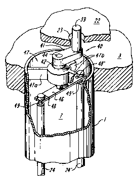
Fig. 1 is a view in perspective, with portions cut away, of an orbital
drive, open-tube, whip rod heat eY~h~n~er accordhlg to the present invention
operated in a flooded mode and in a non-vertical orientation;
Fig. 2 is a view in perspective, with portions cut away, of another
embodiment of an orbital drive, open tube, whip rod- heat eY~h~nger accordh~g tothe present invention operating in a falling film mode and in a vertical
orientation;
Fig. 3 is a detailed view in perspective, with portions broken away,
of the positive rod orbital drive shown in Fig. 1 and also showing a thermal jacket
to enh~nce the flow of a boiling refrigerant over the outer surface of each heattransfer tube;
Fig. 4 is a simplified view in holi~onlal section of a heat transfer
tube and orbiting whip rod illustrating the dynamic forces acting on the rod andthe liquid in the tube when operated in a falling film mode;
Fig. 4A is a force vector diagram showing the dynamic forces acting
in Fig. 4;
Fig. 5 is a detailed view in perspective of an orbital plate drive for a
heat eY~h~-eer accordhlg to the present invention where an orbiting top drive
plate is ~osilively coupled to one of multiple pairs of freely rotatable, dynamically
b~l~nce~l whip rods;
Fig. 5A is an alternate embo~liment colles~,onding to Fig. 5, but
using four whip rods;
Fig. 5B is a schematic top plan view sharing a balance arrangement
where groups of single rods are driven 180 out of phase with one another;
Fig. 6 is a dia~,l;1.,..1-~tic top plan view showing the wear and
tolerance instllsilivil~ of the orbital drive of Figs. 5 and 7 exemplified by five tube
centers al .... aS and five associated drive plate coupling points bl ... b5;
-- 16 --
wo 9s/00808 216 ~ 6 6 1 PCT/US94/07016
Fig. 7 is a detailed view in perspective colles~ollding to Fig. 5, but
showing an alternating embodiment utilizing a pair of offset flat whip rods and
z-llxili~ry radial force spring mounts according to the present invention.
Fig. 7A is a detailed view in perspective of an alternate, four rod
embodiment of the embo~lim~nt shown in Fig. 7; and
Fig. 8 is a highly simplified schematic view of a thermal storage
system using a heat eYrh~ngçr accordillg to the present invitation and an ice
burner according to the present invention.
Detailed Description of the Preferred Embodiments
Fig. 1 shows a heat llans~er apparatus 100 accordhlg to the present
invention that uses an orbital whip rod drive. A container or outer shell 2
encloses a number of heat transfer tubes 1. A top tube sheet 3 and a lower tube
sheet 4 togelher with the tubes 1 divide the inside volume of co~-t~;..er 1 intoco...~ lllents 5, 6 and 8. Colll~alllllent 8 represents the outer or shell side of
the heat l,~rer system. The inner or tube side in~lndes both an upper chamber
5 and a lower chamber 6 as well as the space inside all of the tubes 1. Each tube
1 provides inner 7 and outer heat transfer surfaces. It is thin-walled and made of
a material with high heat transfer properties such as copper or steel. The tube
may have certain surface tre~tm~-nt~ such as grooving that may be used to
e~h~nce the heat lla,~srer properties for either the inside or the outside surfaces
of the tube.
A first process media I may be introduced into chamber 8 via a
cond~lit or no77les 9 and 10 to eY~h~nge heat through the wall of the heat l,al~re
tubes 1 with a second process media II, which may be introduced into the upper
chamber 5 via conduit 11 as well as condllit 12 at the lower chamber 6. For
216~i61
WO 95/00808 PCT/US94107016
example, for des~lini7~tion, the media II is seawater and media I is a heated
vapor such as steam. For m~king ice slurries, media II is water with an additivethat promotes the formation of large ice crystals in the water rather than on the
tube wall. Media I is preferably a ples~uli~ed refrigerant that boils at the outer
surface to form a two phase vapor/foam stream. A suitable additive for water is
ethylene glycol (automotive antifreeze), propylene glycol, milk, seawater, calcium
ma~n~cillm acetate, and certain inorganic salts such as sodium bicarbonate that
form anhydrous crystals. A 3 to lO~o solution is typical. S~lcces~flll additivesresult in the formation of very fine, powdery ice crystals. Additives that do not
work form ice crystals as large, flat flakes. A~l)ropliate solutions, when left in an
o~.li,la,~ home freezer overnight will be slushy, and stirrable; unsuitable additives
and solution strengths will result in a frozen mass.
When the apparatus 100 is used in an ev~pol~tion process, the
media I in the chamber 8 having a higher temperature will be used to evaporate asecond media II inside chamber 5 having a lower temperature. In particular,
steam may be introduced into chamber 8 via conduit 10 and upon condensing
onto the outside surface of tubes 1 to form condenc~te which flows out from the
outlet 9. The heat thus rele~ced will be used to evaporate the media II, a fluidintrod~l-ed into the upper chamber of 5 via conduit 11 feeding to the top of thetube sheet 3. In one form of feed distribution, the feed will be distributed over
tube sheet 3 in the form of a liquid pool 24. This liquid will then flow down into
the tubes 1. The latent heat released by the condensation of the steam inside
ch~"l,er 8 passes through the wall of tubes 1 to evaporate the liquid inside thetube. Vapor generated may flow either through the upper end of tubes 1 and exit
from outlet 11a (in phanlolll), or in another arr~ngement to flow dow"w~rd in
tubes 1 co-current with the flow of the liquid stream to flow out from the outlet
12 at the lower end of chamber 6.
-- 18 --
216~66 1
WO 95/00808 PCT/US94/07016
-
Inside each tube 1 there is a whip rod 24 which is driven to revolve
in an orbital manner inside the tube. The orbital motion is represented by curved
arrows 300. This orbital motion will generate a centrifugal force to cause the
whip rod to bear upon the inside surface of the associated tube 1 with the rod
~li~ed with the tube axis. In a falling film mode of operating shown in Fig. 2,
this motion will spread liquid a stream into a thin and unirollll liquid film tof~^ilit~te its ~v~olalion and thereby to increase the heat transfer coefficient. In
the flooded mode shown in Fig. 1, the rod motion creates turbulence in the feed
liquid II and it can control the deposits of solids on the inner tube surface.
The mass, configuration, and speed of revolution of the rod will vary
with the application, mode of operation, the condition and size of the tube and
other factors in a manner that will be readily understood by those skilled in the
art. For inct~nce, for seawater des~lin~tion~ one desirable feature would be to let
the orbital motion of the rod ...~ e the scale forming tendency of the various
ingredients dissolved in the seawater which may precipitate out to form scale
while the water is eva~olated. In the case of the conrçl~l~alion of some food
products, the rod should be able to push the concçntrated fluid against its
~iSCOSil~ while at the same time not d~m~ging delicate material inside the
concellllate. For m~kin~ ice slurry the direction of the flow of the heat will be
from the inside of the tube to its outside so that ice crystals form as the liquid is
chilled and flows downw~rdly. For this application the function of the rod will be
to disrupt and dislodge the incipient formation of ice crystals that may stick to and
grow from the inside surface of the tubes 1.
In the configuration of Fig. 1, the rods 24 are ~lefelably free-
st~nding inside the tubes 1 with their lower ends resting upon a plate or the shell
lower end wall 23 with some suitable low friction surface for the rods to slide
-- 19 --
2165561
WO 95/00808 PCT/US94/07016
upon to perform the orbital motion 300. In the preferred form for flooded mode
operation, this orbital motion of the rods 24 is ~ctl~ted by a pair of vertically
sp~ce~l, holi~ontally eYten~ling drive plates 22,22~. These plates can be supported
on fleYible shafts 93 and 93 which are anchored at onè end to the end covers of
2a, 2b, the shell 2 and at the other end to the plates æ and 22~. These fleYibleshafts 93 and 93 ' are rigid in their torsional mode, but fleYible in their bending
mode. A u~l-v~l~al joint would function in the same manner. Suspended in this
m~nner, plates æ and 22~ will have freedom for translational motion, but not fortorsional motion.
At the center of plates 22 and 22~, there are bnchingc 21 and 21
through which a shaft 17 passes and is driven to revolve by cranks 16 and 18
~ttr^he~l to a center shaft 14, which in turn is driven by motor 13 through bearings
and seals 15 mounted on the cont~ er 2. Thus when the motor 13 operates it
produces an orbital motion of the plates 22, 22 ~ which then drive all the rods 24
ured in holes 23 in a similar orbital motion. The radii of the cranks 16 and
16~ are ~(ljllcted so that the orbital rods 24 will orbit freely inside tubes 1. The
diameter of the holes 23 is conci~erably larger than the diameter of the rods 14 to
allow each rod to make its own adjustment while it orbits inside the tube 1.
Fig. 1 shows the orbital rod heat eYch~nger 100 rigidly ~tt~ he~l to a
flat plate 200 which is angled away from the holLcon~al to simnl~te the deck of a
ship being tilted in a heaving motion. The eYrh~nger 100 is correspon-lingly
angled into a non-vertical orientation. For such moving base operation, none of
the traditional liquid level controls and feed liquid distribution methods associated
with falling film modes of operation would be effective. On the other hand, feeddistribution is totally unaffected by orientation when the tube side chamber 1, 5, 6
-- 20 --
wo 95/00808 21 6 ~ PCT/US94/07016
is completely flooded, and the feed liquid II may be introduced from either end of
the tubes. The whip rods 24 are driven to orbit by two drive plates 22, æ ~, oneat each end of the rods. This is a more positive drive tec~nique than driving from
only one end of the rods, but it is sllull~ly preferred in moving base or non-
vertical operation and for operation with a totally flooded tube side chamber.
Fig. 2 shows the cut away view of an orbital rod heat transfer device
100' (like parts in the Figures having the same number) using a single drive plate
22 monnted above the top tube sheet 3. The orientation of the eYç~l~nger 100~ is generally vertical and the whip rûds 24 are hung through the holes 23 by
holi;Gonlal pins 25 secured to one end of each rod and sized so that they cannotfall through the holes 23 regardless of the position of the rod with respect to the
hole. This mo~ ;..e arr~ngP-m~nt allows for simple "drop in" ~ccçmbly, or
disassembly for repair or maintenance. The orbital motion of the rods inside theheat llansr~l tubes 1 is again ~wered by the motor 13, lral~lllilled via the shaft
14 through the be~illg 15 to turn the crank 16 and crank pin 17', which
introduces the orbital motion to bearing 21 at the center of plate 22. Plate 22 will
follow the circular motion of crank 16 with true circular orbital motion, i.e.
without rotation, bec~llce all whip rods are confined to move in circular motion as
if the plate were guided by multiple cranks. The fol~,iving nature of this multiple
drive situation against wear and m~mlf~ct~lring tolerances results from m~king
holes 23 significantly larger than rods 24. By way of example but not of
limit~tion, if the tubes are 1.50 inch in inside diameter and four feet (1.22 m)long,
the rods are 3/8 inch (0.94 cm) stainless steel of somewhat longer length, and the
holes 23 have a diameter of about 5/8 inch (1.59 cm). The clearance between
rods 24 and holes 23 also serves as the inlet of the feed to each tube when the
eY~ ,.ger is operated in a falling film mode, as shown in Fig. 2. While the feed
-- 21 --
216S6~1
WO 9S/00808 PCT/US94/07016
lubricates the hole 23-to-whip rod 24 coupling, the rods in turn keep the holes
from clogging with debris such as ice particles. - ` -
With the rods h~neing from their upper ends, there is no obstructionat their lower ends, thereby allowing the free flow of ice slurry 27 into the drain
hole 28 and exit through conduit 12 to the intake of a suitable pump (not shown)that propels it to a storage tank or, at least in part, in a recirclll~tion loop back to
the eY~h~lleer 100~. Sollleli",es, it may be desirable to extend the rods beyond the
lower tube sheet and closer to the bottom. By so doing, the added mass of the
lower free end of the rod will increase the contact ,~ les~ule of the rod against the
lower inside surface of the tube, exactly where the concellLlalion of ice slurry in
the flow stream reaches its m;lx;~ and has the greatest tendency to freeze up.
The extended ends re~c~ine toward the bottom surface also help to stir up the ice
slurry to enh~nce its flow into the drain hole 28.
When the eYrh~nger 100~ is operated as a freezer or chiller, liquid
refrigerant is introduced into chamber 8 through inlet 9 and evaporated upon
cont~ct with the o~ltcide surface of heat transfer tubes 1. The vapor thus
pro~l~lce~l will exit from outlet 10 into a con~encine unit (a st~n-1~rd commercial
combination of co",plessor, cQn~3e~cer, receiver and suction ~rC~lmnl~tQr)~ which
returns the liquid refrigerant back to inlet 9.
The rhilling effect associated with eva~olating the refrigerant sucks
the heat from the water flowing down the inside surface 7 of the tubes 1. The
water then becomes a partially frozen ice slurry. The orbital motion of the whiprod 24 pushes the water to revolve around the inside surface of the tube in front
of the rod and leaves a thin film behind the rod. The combination of the t_in
wo 95/00808 216 5 6 6 ~ PCTtUS94/07016
film, complete tube wetting, and turbulent wave front of the flow stream producean i""~ruved heat transfer property inside the tube 1.
In this freezer application, it is desirable to enh~nce the
cryst~lli7~tion of the ice inside the body of feed water. Ideally, crystal growth will
occur in the turbulent flow stream produced by the rod movement rather than the
tube wall. In tests with 5% c~lrinm chloride sollltion, the fluid leaving a single
tube test unit was initially supersaturated (subcooled several degrees C below
equilibrium r,ee~llg telll~)elature). At one point, the solution turned white as a
cloud of fine crystals spontaneously nucleated to relieve the supel~alulation.
Blowdown temperature quickly climbed to the equilibrium value and rem~in~-l
there for the duration of the test. This spontaneous nucleation phenomenon
:~Up~Oll:~ the hypothesis that crystal growth occurs in the bulk solution in front of
the whip rod rather than on the tube wall. However, there is no clear or
generally agreed-upon underst~n~ling of the me-~h~ ... by which the ice forms.
The rods typically revolve at about 400 to 700 rpm, or about 10
times a second. This is much faster than the 1/2 to 1 second n~ocess~ry for water
to free fall down the 4 foot (1.22m) long tube. Therefore, the water actually flows
along a long shallow spiral path, co~ ly being pushed by the rod 24. This
reduces the o~o, ~u~uly for crystals to grow upon the wall.
On the refrigerant side, heat l,~rer pe,~""ance can be enh~nre~l
by various means such as a grooved surface to increase the surface area exposed
to the refrigerant. However, applicants have found that with a vertical tube heat
e~c~ ~r it is advantageous to use a concentric, tubular jacket 35 open to a flowof the refrigerant at its top and bottom and to enhance the circulation of the
refrigerant through percolation, as shown in Fig. 3. The jacket 35 restricts boiling
-- 23 --
21~6~ 1
WO 95/00808 PCT/US94/07016
of the refrigerant to the ~nmll~r space 37 between the heat ~Ych~nge tube 1 and
jacket 35. It appears that a strong convection flow may be established with
lighter, vapor bubbles driving a fluid stream rising rapidly along the heat transfer
surface. The resl-ltine high vapor velocities are believed to create shear forces
that subst~nsi~lly illlpl'OVe the boiling side film coefficient and make the heat flux
more unirollll over the tube. While first thought beneficial only for orbital ice
makers, the thermosyphon tube concept is now seen as having advantages for
vertical tube heat ~Ych~ngers with boiling on the shell side in general. With aneYternal se~ tor vessel (to separate the two phases) and double tube sheet
co~ ction, this thermosyphon construction and theory of operation could also
be extended to holi~onlal tube heat eYch~n~ers.
With the jacket 35 used at the outside of the tube 1, a typical heat
transfer coefficient of an orbital freezer is about 800 BTU/hr-ft2-F for a system
with 1.5 inch OD steel tube, and a 3/8 inch OD stainless steel whip rod, orbiting
at 700 rpm. With an 8F temperature difference, the heat flux would be about
6000 BTU/hr-ft2. R22 has been used as the refrigerant while S~o ethylene glycol
or 3.5~o salt were typical additives to the feed liquid.
Fig. 4 and Fig. 4A illustrate the dynamics of the physical interaction
between the whip rod 24 the feed liquid, and the tube 1 as the rod 24 is pushed
by the opening 23 of the orbital plate 22 into an orbital motion represented by
the circular arrow 300 concentric with tube 1. A d-~w~w~rdly moving fluid
stream 43 is pushed by whip rod 24 in front of its orbital motion. Force 60 is
the cellllilugal force of rod 24 driven to revolve inside tube 1 by force 61 derived
from the movement of the openings 23 of plates 22 and 22 ~ that drive the rod.
This cel,l,irugal force is reacted by the hydrodynamic force 63 acting upon the
surface of rod 24 when the fluid is being pushed by the rod.
-- 24 --
2165661
WO 95/00808 PCT/US94/07016
Fig. 4A is a force equilibrium diagram showing the physical nature
of the balance of these force vectors more clearly. Essentially the tangential
component of vector 63 is balanced by vector 61 which is directly related to thedrive power supplied by the motor 13. The radial component of vector 63 is
b~l~nced by the cen~lirugal force which is a function of the speed, diameter anddensity of the rod. Since the speed and the diameter of the rod also affect the
characteristic of vector 63, only the density of the rod is an independent control
factor.
In a complete system the sllmm~tion of the cellllirugal force of all
of the whip rods and that of the drive plates represents a revolving dislllll,hlg
force acting upon the total system to give it a sh~kine motion.
It is also important to note that Fig. 4A is a hypothetical equilibrium
diagram of the three force vectors 60, 61 and 63 acting in a plane perpendicularto the center line of the tube 1 at the middle of the length of the tube. This
olhesis is a good description of the forces acting on the moving rod 24 when
the rod is driven by two drive plates acting at the two ends of the rod. In the case
when the rod is driven from only one end, a moment occurs since the drive force
61 and the center of the reaction force 63 are no longer acting in the same plane.
The reaction to this tilting moment comes from the ;ulvalule of the
tube and the rigidity of the rod. More specifically, the cenllirugal force 60 urges
the rigid rod to align itself flush the tube wall, in parallel with the tube center
line, where the ~;ulv~lure is zero. Thus with the help of the ce~ irugal force 60,
the rod tends to revolve in parallel with the center line of the tube as if being
guided by a bearing. As noted above, in certain applications, such as the
production of an ice slurry, ice can ~c~lmlll~te and/or grow more at the lower
tube end (~..,..;..g a vertical orientation) than at the upper end. As the
-- 25 --
2165~ 1
WO 95/00808 PCT/US94/07016
eY<~nger is operated with enhanced heat fluxes, this situation may overcome the
rod ~ligning affect of the cenL~irugal force 60, and eventually can cause the
a~paralus to freeze up. Applicants' solution to this problem is described below
with reference to Fig. 7.
The flow stream 41 is highly turbulent. In freezer applications it is
where most of the cryst~lli7~tion of the ice is presently believed to occur. Some
incipient roll"&lion may also occur on the surface of the tube in the thin film left
behind the rod. The turbulence in the flow stream 41 and the mech~nical action
of rod 24, in combination with the action of the additive as described above, are
believed to yrcvcnl these incipient ice formations from growing into a thickenedhard ice patch or co~ting that is so firmly ~tt~ed to the tube wall that it is
hlAI,ossible for the rod to remove it.
Fig. S shows another significant feature of this invention, an orbital
drive formed by a single orbital plate 22 that drives multiple cranks 40, one
associated with each heat l,~lsrer tube 1 (like parts in dirrerclll embo~liment.c
again having the same refercnce number). One such tube is shown in detail in
Fig. 5. A main rotatable shaft 44 of the crank is guided by a bushing 42, which is
secured by lhlee-lcgged, spider-like bracket 47 to keep the center line of shaft 44
concentric with tube 1. The bracket is ~lesigned with one rigid arm 47a and two
deflect~ble arms 47b so that the assembly can be snapped into the tube and be
self-centering. Detents shown in Fig. 7 are provided in the tube periphery to
engage bracket arms positively with a snap-in engagement. These detents are
formed during the usual l~dlo~w~ging process to bond the tubes 1 to tube sheet 3.
Note that the bracket 47 and crank 40 can be top-loaded into the tube 1 for easeof assembly and ~lic~ccembly for m~inten~n~e.
The upper end of crank shaft 44 is secured to a crank arm 41, which
in turn carries a crank pin 39 which is caplllred in, and thereby mechanically
-- 26 --
2165661
WO 95/00808 PCT/US94/07016
coupled to the drive plate 22. Each pin 39 is captured in an opening 23 in the
plate which, as described above, is preferably oversized with respect to the pindiameter. The lower end of the shaft 44 engages a revolving member 46, shown
here as a flat arm with two slots 48 and 48~ at its two ends. These two slots fit
loosely over rececce~l necks portions 49 and 49 ~ formed in the rods 24 and 24 ~ at
their upper ends to support them. At the same time this mounting arrangement
allows the rods to roll inside the tube 1 as the crank ~csemhly is driven to revolve
by an orbital motion of the orbital plate 22 in a plane generally orthogonal to the
rods 24, 24 ~ and to the aY~is of the tubes 1. Note that this embodiment is bestsuited for single top plate drive with a vertical orientation, but can be used in
dual plate drive, as in non-vertical orientations. It is also significant that the
....,~...li.~g of the rods is not rigid. They can move freely in a radial direction
within the slots 48, 48 ~ which provides the advantages of a stiff but fleYible whip
rod and avoids the pre~icioll, tolerancing and wear problems that characterize
traditional rigid wipers.
Figure 6 illustrates how the orbital drive of Figs 2, 5 or 7
rccommodrtes wear and mrmlf~rtllring tolerances with reference, for the sake of
simplicity of presentation, to a five tube heat ~Y~llrnger with the tubes arrayed in
a single circle, eqllirn~llrrly spaced about a center S of tube sheet 3 of Figs. 2, 5
or 7. The star shaped pattern al - a2 - a3 - a4 - a5 represents the tube pattern on
tube sheet 3 with the points co-~esponding to the center lines of tube 1, as well as
the center lines of crank shafts 44 in Fig. 5 and Fig. 7 embodiments. S represents
the center line of the main drive crank shaft 15. In principle S should be located
at the geometric center of the tube pattern a,--a", a~c shown. The heavy lines 3-
1, 3-2, 3-3, 3-4 and 3-5 between points a represent the connecting web of the tube
sheet 3, or any equivalent structural member or members.
-- 27 --
2165661
WO 95/00808 PCT/US94/07016
Points b, - b2 - b3 - b4 - b5 in Fig. 6 and the light lines 22-1 .. 22-5
joining them represent the orbital drive plate æ with its geometric center located
at T. In principle, patterns a and b should be idèntical so that when the orbital
drive plate pattern b is displaced translationally from the tube sheet pattern a, all
displacement vectors r are identical. In particular, when r is fiYed by the radius of
the crank arms, pattern b will move in a true circular orbital motion.
The ~lim~n~ional tolerance problem may be eY~minç~l at each of the
parallelograms b; - T - S - ai - b; to check the ~ccllm--l~ted dimen~ion~l erroraround the loop. The tlim~ncional error results from a combination of wear,
bearing play, m~n~lf~chlring tolerance in the tube pattern, and off-center tolerance
in the bracket 47. In the orbital drive plate design, all the ~c~lmlll~ted erroraround the loop b; - T - S - a; - b; can be easily accommodated by a typical 1/16
inch gap between the drive hole 23 and the crank pin 39. This gap is representedby the circles Cj ~ulloullding the points bj
When the orbital plate drive of this invention is used to drive a
crank (whether an orbital rod or a full-fledged, collvenlional style of Fig. 5) with
a radius r of 1/2 inch, this 1/16 inch tolerance results in a 5 phase shift of the
crank angle in that tube with respect to the main drive crank 16. This in turn
tr~nCl~tçs into a very small shift in the loading pattern of the crank re~ction forces
upon the drive plate. Operating experience has demonstrated, however, that the
orbital drive plate arrangement is very fol~ivhlg to wide variations in the size and
shape of the drive holes 23. In short, not only does this orbital drive efficiently
slllil an orbital motion on ~im~llt~nçously to multiple tubes, it does so in a way
that is sllbst~nti~lly ince~ ;ve to wear anywhere along the drive and has no parts
that require ..~ r~chlre or assembly to strict dimensional tolerances. The driveis durable, easily m~int~in, and has a co...~ tively low cost of m~nllf~chlre. It
-- 28 --
216566 l
WO 95/00808 PCT/US94/07016
also requires few parts. For example, there is no complex gear train to transmitrotary power to the multiple tubes, nor for most applications, is a lower drive
plate necessary.
Fig. 7 shows the use of the crank assembly to drive a pair of
diametrically opposed, flat whip rods 50 and 50' with a generally rect~n~ r
cross section that 1) enh~nres turbulence in the feed liquid in the tube as it moves
and 2) has a le~ , chisel-like edge ~dj~cent the inner tube wall 7 to remove
solid deposits (e.g. ice crystals when used as a freezer), that ~ccllmlll~te on or
grow from the tube wall.
Another principal feature of this invention is an arrangement for
providing an ~llYili~ry, radially-directed force on the rods 50,50~ to supplement
the cellllirugal force 60. A presently prefelled implement~tion is a pair of springs
51 and 51~. The eng~gin~ force of the whip rods against the tube surface 7 is
then a combination of the cenllirugal force, the gravitational component of spring
51, and the elastic force of the springs 51, 51~. Note that this produces a non-rigid mo....~ for the rods 50, 50~, as do the slots 48, 48 in the Fig. 5
embo~limerlt This "loose" radial positioning helps to achieve the objects of this
invention without precise merl~ g, tolerancy and assembly.
In use in a freezer/chiller, a simple spring-loaded whip rod as shown
in Fig. 7, operating at a low speed but with a high torque, can allow ice to form as
a thin co~ting on the inner tube surface 7 to a degree that would be lm~cceptable
when the only radially directed colllyollent of force was cenllirugal, whether the
rod or rods were driven ~as~ivcly or positively. As the ice coating grows to an
m~cceptable thickness, it is simply scraped off by the brute force of this drive.
The resllltin~ crystal shape of the ice shaved from the wall may be preferred for
-- 29 --
21~661
WO 95/00808 PCT/US94/07016
certain applications. Note also that low speeds, e.g. less than 100 rpm, ordinarily
develop an insufficient ce-lllifugal orce to m~int~in the ~lignment of the rods and
to control solid deposits on the wall. The spring mount makes lower speed
operation possible, with reduced vibration and other related problems.
When m~hng an ice slurry for thermal storage, it is desirable to
encourage the cryst~lli7~tion to occur in the turbulent duwllw~rd flow stream 41ahead of the whip rod, rather than on the tube surface 7. Once the ice ~tt~ches
to the surface, it is more difficult to scrape off. This layer of ice encouragesfurther growth on the wall. The danger is that a thick layer of ice will grow which
can lead to an upset condition where the rods are frozen to the tube. A long
meltdown time may be nee~le~l to recuver from such an upset. In this situation,
more careful attention must be paid to the operating conditions to be sure that
the additive and whip rod can control the ice growth on the walls.
To f~lit~te operation as a freezer, particularly in the ice-slurry
mode, hooks 52 and S2~, shown in ph~ntom in Fig. 7, are secured at one end to
the whip rods 50 and 50~, and hooked at the other end over the center shaft 44.
The hooks act as rigid stops that set the m~ travel of the rods 51,51' away
from the shaft 44 in response to the elastic force of the springs and the cellllirugal
force 60. The hooks "~ ;n a narrow well-defined gap between the whip rods
50 and 50' and the inner surface 7 of tube 1 typically a few mils (0.004 inch,
0.010 mm).
It is signifir~nt to note that the use of two rods in each tube that are
spaced ~n~ rly by 180 from one another produces a good self b~l~n~n~ of the
rods as they move over the tube surface 7. Of course, more than two rods may be
-- 30 --
21~i66~
WO 9S/00808 PCT/US94/07016
used. Four rods spaced ~n~ rly by 90, as shown in Fig. 7A, offers the same
balance benefits with increased rod action at a given orbital speed.
For a small system several loosely swinging whip rods in one
cylinder shown in Fig. 5A may be more economical than the use of several tubes
each with only one rod and driven by a multiple drive mech~nicm such as an
orbital drive or a gear train. In the experimental stage for testing the ~ropel ~ of
the whip rods, one tube in a concentric heat transfer jacket with whip rods driven
in the same m~nner as Fig. SA has been found to be eYcee~lingly co~lvel~ient andeconomical.
Using a crank to drive pairs of whip rods in each tube to
m~int~in the dynamic balance as tliccllcced before is easy to see. if only one rod
is used in each tube, the dynamic b~l~nring may be accomplished by pairing
groups of rods with diametric opposite phase angles as shown in Fig. SB. In Fig.SB the 19 rods in 19 tubes is divided into two groups of one group of 10 rods asr~resented by small circles 24 and another group of 9 rods as represented by thesmall dots 24~. In general, dynamic b~l~nring must be considered in both the
translational mode and the torsional mode. The target is to have the combined
C.G of the opposhl& groups of rods to revolve around a common aYis (preferably
to be at the center line of the overall system) at 180 phase angle with respect to
each other and with a nearly equal number of rods in each group.
The typical heat flux of 6000 BTU/ft2- hr cited earlier represents a
practical upper limit for the orbital rod configuration of Fig. 2 with the exemplary
op~lalillg conditions as given above. This orbital rod configuration has been found
to have only a modest ability to remove incipient ice formation and avoid an
upset when the heat eY~h~nger is operated at commercially desirable levels, near
-- 31 --
~1~566 ~
WO 95/00808 PCT/US94107016
6000 BTU/ft2-hr fluY. value. This is because the eng~ging force of the rolling whip
rod depends only upon the ce,ll,ifugal force 60, which is limited in m~gnitl-dë
under the best chc~-...c~nçec, and becomes smaller with the shrinking orbit radius
as ice builds up inside the tubes 1. In this situation it is valuable to have analarm to stop the operation as soon as-incipient upset is detected to cut down the
~-ecec~ry recovery time.
By co..,l~A.ison with the confi~-ration of Fig. 7, in the event that
incipient ice formation (believed to be dendritic crystal growth) does occur on the
surface 7, the spring controlled gap provides a gentle scraping effect to ~rGvc;nl its
further growth, beyond the gap. This is important to avoid an upset. For this
purpose, a spring controlled gap offers more fleYibility than a rigidly mounted rod.
In brief sllmm~ry, driving the whip rod "directly" with the orbital
plate, as opposed to oll,iLillg the entire heat PY~hA..ger or the tubes, greatlyreduces the mass being driven and reduces the strain and design requirements on
the drive mecl~ Driving ~directly~ is limited, however, to supplying the
l~lgenlial force needed to push the rod fol~v~d; the whip rod loading against the
tube results indirectly from the cenLlirugal force, which is a relatively small
magnitude force and can not fully utilize the torque capability of the orbital drive.
By driving the whip rod with an orbital plate via cranks, particularly with the
additional option of loading the whip rods with springs, the orbital heat eY~h~nger
can fully develop the capability of the orbital drive heat transfer device for
procescine fluids with higher viscosity, particularly the ...~ ~ct~re of ice slurries.
Fig. 8 shows a complete heat eYrh~nger system, in this in.ct~nce a
thermal storage system 130 inrhldes an ice slurry m~hine 100 col~llucted and
operated accordillg to the present invention, an ice slurry storage tank 111, and a
-- 32 --
wo 95/00808 21 6 5 6 6 1 PCT/US94/07016
building 112 or other installation where the "cold" stored in the tank 111 is
supplied via a distribution system 118 (shown schematically as a coil) by melting
the ice. The distribution system is a closed loop. It is significant that if them~hine 100 is operated in a flooded mode, the system can supply cold to a
high-rise building using only the normal circulation or supply pump for the system
and no level controls.
If chilled water is distributed, the stored ice must be melted or
cd". Dc~ .d;.~g on the placement of the m~hine 100, gravity and
convection can drive or assist the circulation. If the ice slurry is l~ )ol led and
distributed, it must be pumped from the tank to the distribution system. In suchcold storage systems, the time periods for m~king and burning the ice are
staggered, and usually have dirre~illg durations. In some applications (such as
cllulches), the ice slurry can be produced and stored in the tank over an
extended period, but burned in a relatively short period.
One special problem of ice storage is that the ice in the stored ice
slurry stored in tank 111 tends to co~ te into an ice mass that floats on the
water. Once used, warm return water is pumped back into the tank to burn the
ice. The warm water tends to channel through the floating ice mass 112. This
reduces the ...~;....,... possible burn rate and it permits the warm water to "short
circuit" to the boll.,lll of the tank while the tank still retains much of its ice
charge. To deal with this problem, a movable nozzle 120 mounted on top of the
storage tan-k- moves about in a pattern to direct the recir~ ted warm water overthe ice mass generally ulurollllly.
There has been described a novel orbital drive heat eYch~nger and
thermal stage system that provide a highly efficient, effective heat transfer capable
-- 33 --
216566 i
WO 95/00808 PCT/US94/07016
of operating in flooded or falling film modes, in vertical or non-vertical
orientations, on a fixed or moving reference body. There has also been describeda positive, mech~nic~l, orbital drive for simultaneous operation of multiple heat
eYch~ngers of the whip rod-in-tube type with a high~applied torque at each tube,and an option ~llxili~ry radial force and rod-to-tubé gap control. This drive ishighly reliable and durable; it is subst~nti~lly insensi~ive to normal wear and
tolerance of parts and assembly. It also provides automatic self-adjustment for
the rods, even when operating with a single end drive and with non-unirol",
resict~nce along the tube to movement of the rods. The drive is also
characterized by a co~ alively low cost derived from a low part count, low
tolerance requirement, ease of assembly, and ease of disassembly for repair or
routine maintenance. There has also been described a thermal jacket that
produces an enh~nce~l heat transfer at the outer surface of the heat transfer tube.
The heat eY~h~n~er and system operate with high energy efficiency, are comp~ct,
scalable, and can operate in closed loop systems without special pumps or liquidlevel controls, particularly cold distribution systems in high-rise buildings.
While the invention has been described with respect to its l,refe,red
embodiments, it will be understood that various modifications and alterations will
occur to those skilled in the art from the foregoing detailed description and the
~co~ lg dla~ ~. For example, while the whip rods and crank pins have
been described as loosely held in openings in a drive plate, they could be
mo~lnte~l in bearings, albeit at an increased cost and a reduction in fluid feedoptions. Also, while the whip rods have been described as hung from the upper
drive plate by pins, they could be hung by more elaborate means for free-st~n-lin~
on their lower ends, anchored flexibly at both ends, or supported by a pivot
~,~lgel,.ent that enhances contact force at the lower end. These alternatives are
believed, however, to be less desirable since they reduce operational options, have
-- 34 --
wo 95/00808 216 5 6 6 1 PCT/US94/07016
an increased cost, or are more susceptible to solids ~cc~lm--l~tion, particularly
when used to make ice slurries. The drive plates can ~ccllme a variety of forms
consistent with the general design objectives and structures described herein, as
can the source of motive power and its coupling to the drive plate. For example,the drive plate can be formed from a rigid, closed loop frame that supports an
array of rings using a network of wires or arms that extend across the frames.
Each ring can ca~l~lre an end of a rod or a crank pin, Also, while the motive
force has been described as supplied by a motor via a main drive shaft and an
eccenl,ic, the drive can use multiple power sources with an arr~ngem~nt to
synchro,~e their operation, a rotary counterweight coupled to the drive plate that
is sll~pe-nded to move, without twisting, in one plane, or the mutually
perpendicular linear drives mentione~ above whose operation is coor-lin~ted to
yield an orbital motion of the drive plate. These and other modification and
variations are intended to fall within the scope of the appended claims.