Note: Descriptions are shown in the official language in which they were submitted.
- l ~166~
The present invention relate6 to an inlet/outlet
chamber for a fluid, for a body ~t of an a~ s
in which this fluid circulates, this`~y ~t or body portion
including a face for inlet or outlet of the said fluid,
the chamber being intended to be connected with a leak-
tight joint to this face.
The invention applies in particular to heat
chAngers~ of the thermosyphon type or of the falling-
film type, treating especially at least one two-phase
fluid, such as the evaporators/condensers of air-
distillation plants, the evaporators of refrigeration
units, the reboilers of distillation columns or alterna-
tively to certain heat ~YchAngers placed in confined
spaces, such as the inter-stage eych~n~ers of certain
compressors.
The invention is to provide an easy inlet/outlet
chamber which is easy to connect to rectangular or square
contours, which is able to withstand internal pressure
particularly well and offers flexibility in the
connection of fluid supply or discharge pipes.
For this purpose, the subject of the invention is
an inlet/outlet chamber as defined hereinabove,
characterized in that at least part of the chamber
consists of at least a spherical or ellipsoidal portion
and of sectors of cones tangential to this spherical or
ellipsoidal portion.
In particular, the inlet/outlet chamber may be
intended to be connected to the entire perimeter of the
said face. In this case, when the said face i~
rectangular or square, the chamber may especially
comprise, on the one hand, two first surfaces in the form
of spherical or ellipsoidal portions, these first sur-
face~ being sub~tantially tangential to two opposite
sides of the rectangle or square and, on the other hand,
four second surfaces in the form of sectors of cones
whose vertices lie on the four corners of the said face,
respectively, and are tangential in pairs to the two
first surfaces.
In one embodiment, the said spherical or
ellipsoidal portions are quarters of a sphere or of an
2 21 ~0~3
ellipsoid, a meridional plane of which is contained in
the said face, and the sectors of cones are half-cones
having an opening of 90.
In one emboA; _-n t, in the case where the said
face is square, the two first surfaces are joined
together into a single spherical surface.
In another embodiment, in the case where the said
face includes two short sides and two long sides, the
said opposite sides are the short sides and the chamber
furthermore inc.ude~ a cylindrical surface connected to
the circular edges, perpendicular to the said face, of
the two first surfaceA.
~ he inlet/outlet chamber may, moreover, include
a feed or discharge pipe tapped off from the spherical or
ellipsoidal portion, either directly or via a transition
surface in the form of a truncated cone, especially a
surface tangential to the spherical or ellipsoidal
portion.
In one ~hodiment, the inlet/o~tlet chamber
projects, with respect to the said part of the body,
beyond the said face, and is also intended to be con-
nected with a leaktight joint to the adjacent face of the
said ~ody ~.
In this case, according to one e~bodiment, the
spherical or ellipsoidal portion is a hemi~phere or a
semi-ellipsoid ~urmounting the top edge which joins the
two ~ace~, and the chamber furthermore comprises another
~formed by three cylindrical surfaces having mutually
perpendicular axe~.
According to an advantageouR embodiment, the
chamber consists entirely of ~urfaces, especially
spherical or ~lipsoidal, conlcai and cylindricai sur-
faces, which are joined together tangentially.
The ~ubject o~ the invention i6 al~o a fluid
c~rculation apparatus comprising a body ~ which
includes a fluid inlet or outlet face and an inlet/outlet
chamber as defined hereinabove, connected with a
lea~tight joint to this face.
When the said boly ~~t is fon~ by a
216~033
-- 3
-
stack of parallel plates defining between them flat
passages, by corrugated spacers arranged between these
plates and by bars for sealing off the passages, the bars
correspo~; ng to the said fluid leaving an inlet or an
outlet free for this fluid, in an embodiment which is
particularly advantageous in the case where the said
fluid is under pressure, the chamber is connected to the
said kody ~ only along zones of this part which
are formed by end portions of plates or by sealing bars.
In one embodiment of the apparatus, the chamber
is joined tangentially to the said b~dy ~
Examples of ~hoA;m~nt of the invention will now
be described with regard to the appended drawings, in
which:
- Figure 1 is a partial side view of a heat
eYch~n~er according to the invention;
- Figure 2 is a plan view of this exchanger;
- Figures 3 and 4 are views respectively similar
to Figures 1 and 2, but correspon~; ng to an alternative
form;
- Figure 5 is a view, taken by look; ng along the
arrow V of Figure 6, of another heat ~Yçh~nger according
to the invention;
- Figure 6 is a plan view of the eYc-h~nger of
Figure 5;
- Figure 7 is a view taken along the arrow VII of
Figure 6;
- Figure 8 i~ a view taken along the arrow VIII
- of Figure 6, illustrating an alternative form;
- Figure 9 is a view similar to Figure 5 of
another alternative form;
- Figure 10 i~ a plan view of another heat
exchanger according to the invention; and
- Figure 11 is a view taken along the arrow XI of
Figure 10.
Figures 1 and 2 show diagrammatically the top
part of an exchanger body 1 of parallelepipedal shape,
elongate in the verti.cal direction, of the brazed-plate
type. This is, for example, the main evaporator/con~en~er
216fiO~3
of a double air-distillation column, of the thermoæyphon
type, intended to evaporate liquid oxygen at atmospheric
pressure or at a higher pressure, which may range up to
5 bar absolute or higher, by condensation of nitrogen.
Reference will be made to this example hereinbelow.
More particularly, the body 1 consists of a stack
of vertical and parallel rectangular plates 2 between
which are interposed corrugated spacers, which also form
thermal fins. Each pair of plates 2 defines a passage of
generally flat shape. At least two ~eries of passages
exist, one of which is reserved for the circulation of
oxygen, constituting the treated fluid, while the other
serves to circulate nitrogen, which constitutes the
auxiliary fluid generating heat during c~en~tion.
On their periphery, the passages are sealed off
by bars. The bars correspQn~;ng to the treated fluid are,
however, eliminated on the top face 3 of the body 1 and
also on its bottom face. The ~YchAnger thus operates as
a thermosyphon, with a8c~n~; ng circulation of evaporated
o~ye~, entr~;n;ng liquid oxygen. The two-phase mixture
leaves the body 2 via its top face 3.
The sealing bars are, moreover, arranged 80 as to
leave free, on the vertical lateral faces of the body 1,
horizontal rows of nitrogen inlet/outlet windows. These
windows are surmounted by inlet/outlet boxes of
cylindrical general shape, such as the box 4 shown in the
drawing, this box being provided at the top part of the
body and 6erving as the inlet for gaseous nitrogen into
the nitrogen passages, which box is fed via a pipe 5.
The body 1 is completed by a bulb 6 which will be
described in detail later.
The body 1 is produced by a stack of plates,
spacer6 and bars, and by oven brazing in a single step.
The inlet/outlet boxes, such as the box 4, are attached
to the body 1 by welding, as is the chamber 6.
The bulb 6 covers the top edge 7 of the body 1,
opposite the box 4, and has a wide opening made as a
single piece whose edge, lying in two planes
perpendicular to each other, is connected with a
_ 5 _ 21~60~3
leaktight joint by welding to the face 3 along the top
edge 8 of the body, opposite the top edge 7, and along
the two other top edges 9 and 10 of the body 1. The edge
of the bulb 6 i8 also connected with a leaktight joint by
welding to that vertical face 11 of the body 1 which is
adjacent to the face 3 alongside the top edge 7. This
face 11 will be designated "front face" hereafter for
convenience.
The bulb 6 includes a rear part 12 in the form of
a half-dome, consisting of three metal sheets:
- a central metal sheet 13 in the form of a
quarter of a cylinder with a horizontal axis 14 contained
in the upper face 3 of the eYc}~nger body 1 and parallel
to the top edges 7 and 8, this metal sheet 13 starting at
the rear edge 8; and
- two cylindrical lateral metal sheets 15, 16, of
the same radius as the metal sheet 13, having a common
axis 17 contained in the face 3 and perpendicular at its
middle to the top edge 7, these two metal sheets starting
respectively from the two lateral top edges 9, 10 of the
same face 3.
The three metal sheets 13, 15 and 16 are welded
together along their double insertion curve 18, which has
the shape of a right-angled V in plan view (Figure 2).
The bulb 6 is completed by a sphero-conical front
part 19. More precisely, this front part essentially
comprises a truncated hemisphere 20 which goes forwards
from the limiting semicircle 21 of the metal sheets 15
and 16, this semicircle lying plumb with the axis 14, and
which overlaps the front top edge 7 of the body 1.
Provided on each side is a metal sheet 22 in the form of
three-quarters of 2- cone, the ~ertox o~ which lie8 o~rer
the corresponding front top corner of the body 1, these
cones having an opening such that they are joined tangen-
tially to the hemisphere along a circle 23 and such that
they have a generatrix coincident with the respective top
edge 9, 10. Those portions of the hemisphere lying within
the circles 23 have been removed.
By virtue of this arrangement, it is possible to
21~60~3
-- 6
make straight line welds on the edge of the bulb along
the three top edges 8 to lO of the exchanger body, and to
complete the leaktight joint of the bulb to the body on
the front face 11. This joint is made along the vertical
edges of the face 11, over a length corresponding to the
generatrix of the cones 22, and then along a circular arc
correspor~;ng to the intersection of the hemisphere 20
with the face 11.
The alternative form in Figures 3 and 4 differs
from the previous one only by the fact that the vertex of
the cones 22, 23 is brought forwards until it lies in the
vertical plane tangential to the hemisphere 20 80 that
the opening angle of these cones is 90.
It may be seen that the edge of the opening of
the bulb 10 is welded along the top edge 8, which is
formed by the top end portions of the plates 2 and of the
sealing bars, along the top edges 9 and 10, formed by the
top end portions of the outermost plates 2A and 2B, and
along the front face 11, formed by the vertical end
portions of the plates 2 and of the sealing bars.
In operation, the two-phase O~yye-~ leaving the
face 3 of the eYcl~-nger body is collected in the bulb 6,
which forms a phase separator, and that part of the bulb
which projects forwards with respect to the body 1 forms
a liquid storage contA; ne~ . The liquid cJxyye" is dis-
charged, for the purpose of recycling it at the base of
the ~YchAnger, via a liquid outlet orifice 24 located
close to the lowermost point of the bulb, while the
gaseous o~yye.- is discharged via a gas outlet orifice 25
located in the vicinity of the uppermost point of the
bulb. The two orifices 24 and 25 lie on the hemisphere
ZO .
In an alternative form, not shown, the bulb 6
could project from the two, front and rear, sides of the
body 1. To do this, the metal sheets 13, 15 and 16 would
be replaced with a single semicylindrical metal sheet
having an axis 17, and arranged on the rear side would be
a bulb part identical to the part 19, overlapping the top
edge 8 and connected, on the one hand, to the
- 2166033
- 7 -
_
semicylindrical metal sheet and to the top edges 9 and 10
and, on the other hand, to the rear face of the exchanger
body.
In yet another alternative form, the width of the
bulb 6, that is to say its vertical dimension in Figure
2, may be less than that of the body 1. In this case, a
semicylindrical metal sheet having an axis 17 or an axis
parallel to this axis 17 is preferably interposed between
the parts 12 and 15 of the bulb.
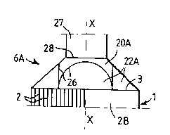
Figures 5 to 7 show a fluid inlet or outlet dome
6A connected by welding along the entire periphery of the
top face 3 of the ~YchAnger body 1, which top face has a
square shape. This dome consists of five metal sheets:
- a h~mispherical central metal sheet 20A whose
vertical central aYis X-X is coincident with that of the
face 3; and
- four metal sheets 22A in the form of half-cones
of 90 opening. Each metal sheet 22A has its vertex on
one corner of the face 3 and is tangential to the metal
sheet 2OA along a semicircle 26.
The hemispherical portions delimited by the
semicircles 26 are removed, and the metal sheets 20A, 22A
are welded together along these four semicircles. The
dome 6A is joined to the body 1 along the eight bottom
generatrices of the half-cones.
The dome 6A, like the bulb 6 in Figures 1 to 4,
is easy to connect to a parallelepipedal eYch~nger body.
In addition, they withstand the internal pressures
particularly well 80 that it is possible to use them in
many applications where the fluid supplied to or dis-
charged through them is under pressure.
Figure~ 5 to 7 al80 show a cylindrical pipe 27
for supplying or dr~;ning-away the fluid, this pipe
having an axis X-X and being connected directly to the
hemisphere 20A along a circle 28. The top spherical cap
of the metal sheet 20A, lying within the circle 28, is
then removed, of course.
However, as illustrated in Figure 8, the pipe 27
may be inclined with respect to the axis X-X, the more 80
2 1 6 6 0
-- 8
the smaller its diameter, the key point being that the
entire perimeter of this pipe cuts the hemisphere.
It may thus be seen that the construction of the
dome 6A gives a great deal of freedom for tapping off
supply or di~charge pipes. This in turn makes it easier
to connect the ~Ychanger body to apparatuses tA~; ng up a
relatively small amount of space, for example in the case
of certain compressor inter-stage heat exchangers.
As an alternative (Figure 9), in order to soften
the transition between the p~pe 27 and the cavity of the
dome, and consequently to reduce the head losses, a
transition metal sheet 29 in the form of a truncated
cone, having an axis coincident with that of the pipe and
an opening equal to 90 for example, may be connected via
its small base to the pipe and via its large base to the
metal sheet 2OA.
Figures 10 and 11 show an alternative form 6B of
the dome 6A, adapted to the case of a rectangular face 3,
for example because the body 1 consists of two identical
exchanger bodies welded side by side along a vertical
weld line 30.
In this case, the dome 6B is produced by
splitting the dome 6A into two half^domes, each
comprising a quarter of a sphere 20B and two half-cones
22A, and by A~;ng an additional, semicylindrical metal
sheet 31 connected via its axial ends to the limiting
semicircles 32 of the metal sheets 20B and via its edges
to the lateral top edges 9 and 10 of the eY~hAnger body.
It may be understood that such an arrangement
allows the dome to be extended at will, 80 that the same
structure can also be used to make up the inlet/outlet
boxe~ of the eY~hAn~er, such as the box 4 in Figures 1
and 2.
In other alternative forms, not shown, the shape
of the chamber 6, 6A, 6B may be modified by horizontal or
vertical affinity in one direction or the other, which
transforms the circular cylinders into circular or
elliptical cylinders, the spheres into ellipsoids and the
cones into cones.
2166~33
g
-
Moreover, whatever its shape, the chamber may be
produced from a single metal sheet by deforming it, in
particular by deep drawing, progressive forming of the
forging type, etc. This is also possible using a small
number of metal sheets, the cutting of which does not
necessarily correspond to the various geometrical
surfaces described above.
In all cases, the cha~her according to the
invention consists of surfaces which are tangential to
each other along their lines of connection. This provides
advantageous continuity of the stress field which
develops as a result of the pressure.