Note: Descriptions are shown in the official language in which they were submitted.
CA 02166167 2001-10-30
(a) TITLE OF THE INVENTION
FASTENING MEMBER
(b) TECHNICAL FIELD TO WHICH THE INVENTION RELATES
This invention relates to a fastening member. This invention
particularly relates to a fastening member, which has a high heat
resistance, a high corrosion resistance, and good mechanical
characteristics, and are useful in various fields, e.g.,
aviation, cosmic, automobile, chemical, marine, and construction
industries.
(c) BACKGROUND ART
Heretofore, fastening members, e.g., bolts and nuts, which
are constituted of metals have been used. However, the fastening
members constituted of metals have drawbacks in that they have
a low heat resistance and are heavy in weight. Due to these
drawbacks, there has been a limit in using the fastening members
constituted of metals in various fields, particularly in the
aviation and cosmic industries.
Therefore, a fastening member constituted of a ceramic
material, which has a high heat resistance and is light in
weight, has been proposed and has attracted particular attention.
However, the proposed fastening member constituted of a ceramic
material has a low toughness, and therefore has the drawbacks in
that cracks are apt to occur and become gradually larger in the
threads of the fastening member; the treads would then break at
a stress markedly lower than the strength of the material. For
these reasons, the proposed fastening member constituted of a
ceramic material cannot be applied to sites which are required
to have a high strength. Thus a need exists for a fastening
member, which has a high heat resistance and a high mechanical
strength and is light in weight.
1
CA 02166167 2001-10-30
(d) DESCRIPTION OF THE INVENTION
An object of a broad aspect of the present invention is to
provide a fastening member, which has a high heat resistance and
a high mechanical strength and is light in weight.
An object of another aspect of the present invention is to
provide a method for the production of such fastening member.
The inventors carried out extensive research and found that
such objects can be accomplished by a fastening member which is
formed from a fibre-reinforced ceramic composite material
comprising a ceramic material and inorganic long fibres, which
are oriented in specific directions and contained in the ceramic
material.
The present invention is based on such findings.
Specifically, the present invention in a first broad aspect
provides a fastening member including: a fibre-reinforced ceramic
composite material, in which a ceramic material is reinforced
with a plurality of at least two oriented layers of inorganic
long fibres. The ceramic material comprises glass-ceramics having
a density ranging from 2.0 to 3.2 g/cm~, and being selected from
the group consisting of Li20-Al~-Mg0-SiOz-Nb205, Mg0-A12-SiOz,
Ba0-Mg0-A1203-Si02, and Ca0- A120z03-SiO2.The inorganic long fibres
having a mean diameter ranging from 5 to 200 ~.m, a mean length
of at least 500 Vim, and a density ranging from 2.2 to 3.2 g/cm3,
wherein the inorganic long fibres are located in the ceramic
material such that the first oriented layer or layers, in which
the inorganic long fibres are oriented in a first predetermined
direction, and the second oriented layer or layers in which the
inorganic long fibres are oriented in a second direction which
is different from the direction of orientation of the inorganic
long fibres in the first oriented layer or layers is or are
laminated alternately. The fastening member has a length and a
width, the length extending in a longitudinal direction and
including an external thread. The direction of orientation of the
inorganic long fibres in the first oriented layer or layers
ranges between 0° and 90° with respect to the longitudinal
direction of the external thread. The direction of orientation
of the inorganic long fibres in the second oriented layer or
2
CA 02166167 2001-10-30
layers range between 0° and 90" with respect to the width of the
fastening member.
By a first variant of this first broad aspect of this
invention, the inorganic long fibres are constituted of (a) an
amorphous substance substantially comprising Si, Ti and/or Zr,
C, and O, (b) an aggregate of the amorphous substance and a
crystalline substance of 500 A or less comprising (3-SiC, and at
least one of TiC and ZrC, or (c) a mixture system of the
crystalline substance and an amorphous material, which comprises
Si0 and at least one of TiOx and ZrOx (O<x<_2) and is present at
a distance of 1,000 A from the crystalline substance. By a
variation of that variant, the inorganic long fibres are such
that the proportion of Si is 45 to 60 wt %., the proportion of
Ti and/or Zr is 0.2 to 5 wt %, the proportion of C is 20 to 45
wt %, and the proportion of 0 is 0.1 to 20.0 wt %.
A second broad aspect of this invention provides a fastening
member including a fibre-reinforced ceramic composite material,
in which a ceramic material is reinforced with at least two
oriented layers of a plurality of inorganic long fibres. The
ceramic material comprises glass-ceramics having a density
ranging from 2.0 to 3.2 g/cm3, and being selected from the group
consisting of LizO-AlzOi-Mg0-Si02-Nb205, Mg0-A1203-Si02,
Ba0-A1203-Si02, B,O-Mg0-A1203-Si02, and Ca0-A120203-SiOz. The
inorganic long fibres have a mean diameter ranging from 5 to 200
,um, a mean length of at least 500 ~.cm, and a density ranging from
2.2 to 3.2 g/cmj. The inorganic long fibres are located in the
ceramic material such that a first orientated layer or layers in
which the inorganic long fibres are orientated in a first
predetermined direction and a second orientated layer or layers
in which the inorganic long f fibres are orientated in a second
direction which is different from the direction of orientation
of the inorganic long fibres in the first orientated layer or
layers is or are laminated alternately. The fastening member
having a length and a width, the length extending in a
longitudinal direction and including an external thread. The
direction of orientation of the inorganic long fibres in the
first orientated layer or layers ranges from 0° and 90° with
3
CA 02166167 2001-10-30
respect to the width of the fastening member, and the direction
of orientation of the inorganic long fibres in the second
orientated layer or layers ranges from 0° and 90° with respect
to
the width of the fastening member.
By a first variant of this second broad aspect of this
invention, the inorganic long fibres are constituted of (a) an
amorphous substance substantially comprising Si, and at least one
of Ti and Zr, C, and O, (b) an aggregate of the amorphous
substance and a crystalline substance of 500 A or less comprising
~i-SiC, and at least one of TiC and ZrC, or (c) a mixture system
of the crystalline substance and an amorphous material, which
comprises SiOX and TiOx and/or ZrOx (O<x<_2) and is present at a
distance of 1,000 A from the crystalline substance. By a
variation of this variant, the inorganic long fibres are such
that the proportion of Si is 45 to 60 wt %, the proportion of Ti
and/or Zr is 0.2 to 5 wt %, the proportion of C is 20 to 45 wt
%, and the proportion of O is 0.1 to 20.0 wt %.
The present invention also provides a method for producing
a fastening member. The method includes the step of embedding a
plurality of inorganic long fibres in a ceramic material such
that the inorganic long fibres are oriented in a first
predetermined direction, thereby obtaining a plurality of first
preforms. The ceramic material comprises glass-ceramics having
a density ranging from 2.0 to 3.2 g/cm3, and being selected from
the group consisting of Li20-A1203-Mg0-Si02-Nb205, Mg0-A1203-Si02,
Ba0-A1203-Si02 type , Ba0-Mg0-A1203-S i02 , and Ca0-Al20zO j-S i02 . The
inorganic long fibres having a mean diameter ranging from 5 to
200 ,um, a mean length of at least 500 Vim, and a density ranging
from 2.2 to 3.2 g/cm3. The next step includes laminating the
obtained first preforms such that the directions of orientation
of the inorganic long f fibres in adj acent f first preforms intersect
each other at a predetermined angle. The next step involves
sintering the laminated first preforms to obtain a fibre-
reinforced ceramic composite material. The next step involves
cutting a piece with a predetermined directivity from the
obtained fibre-reinforced ceramic composite material. The final
4
CA 02166167 2001-10-30
step involves shaping the cut piece to obtain a fastening member
having a thread.
The fastening member in accordance with aspects of the
present invention has a high heat resistance and a high
mechanical strength and is light in weight.
Therefore, the fastening member in accordance with aspects
of the present invention is applicable to sites to which the
conventional fastening members constituted of metals could not
be satisfactorily used due to their low heat resistance . Thus the
fastening member in accordance with aspects of the present
invention are useful in various fields.
(e) DESCRIPTION OF THE FIGURES
In the accompanying drawings,
Figure 1(a) is a perspective view showing an embodiment of
the fastening member in accordance with an aspect of the present
invention, which is constituted as an external thread member;
Figure 1(b) is an enlarged perspective view showing part of
the external thread member of Figure 1(a);
Figure 2(a) is a perspective view showing a different
embodiment of the fastening member in accordance with an aspect
of the present invention, which is constituted as an internal
thread member;
Figure 2(b) is an enlarged perspective view showing part of
the internal thread member of Figure 2(a);
Figure 3 is a perspective view showing preforms utilized for
the fastening member in accordance with an aspect of the present
invention;
Figure 4 is a perspective view showing a fibre-reinforced
ceramic composite material utilized for the fastening member in
accordance with an aspect of the present invention;
Figure 5 is a schematic perspective view showing a direction
in which an external thread member serving as an embodiment of
the fastening member in accordance with an aspect of the present
invention is cut from a fibre-reinforced ceramic composite
material; and
CA 02166167 2001-10-30
Figure 5 is a schematic perspective view showing a direction
in which an external thread member serving as an embodiment of
the fastening member in accordance with an aspect of the present
invention is cut from a fibre-reinforced ceramic composite
material; and
Figure 6,is a schematic perspective view showing a direction
in which an internal thread member serving as an embodiment of
the fastening member in accordance with an aspect of the present
invention is cut from a fibre-reinforced ceramic composite
material.
Examples of the inorganic long fibres utilized in
aspects of the present invention include inorganic long
fibres having a composition of silicon (Si), titanium
(Ti) and/or zirconium (Zr), carbon (C), and oxygen (O).
Specifically, the inorganic long fibres should prefera-
bly be constituted of (a) an amorphous substance sub-
stantially comprising Si, Ti and/or Zr, C, and O, (b)
an aggregate of the amorphous substance described above
and a crystalline substance of 500A or less comprising
~-SiC, and TiC and/or ZrC, or (c) a mixture system of
the crystalline substance described above and an amor-
phous substance, which comprises SiOx, and TiOx and/or
ZrOx (0<x<2> and is present in the vicinity of the
crystalline substance.
The vicinity in (c) above is preferably the
region at a distance of 1,OOOA or less from the crys-
talline particles.
The proportions of the elements in the
inorganic long fibres. specifically exemplified above
should preferably be such that the proportion of Si may
6
CA 02166167 2001-10-30
be 45 to 60 wt~, the proportion of Ti and/or Zr may be
0.2 to 5 wt~, the proportion of C may be 20 to 45 wt~,
and the proportion of O may be 0.1 to 20.0 wt~.
As the inorganic long fibres having the
composition described above, commercially available
products, e.g. the product available under the trade
name of TYRANNO FiBERTM and suppl i ed by Ube I ndus tr i es ,
Ltd., may be used.
As the inorganic long fibres described above,
besides the inorganic long fibres having the composi-
tions described above, it is possible to use silicon
nitride fibres, silicon carbide fibres, alumina fibres.
zirconia fibres. carbon fibres. or the like.
Also, the inorganic long fibres described
above should preferably have an inclined composition
structure, in which the outermost surface layer of each
fiber has a composition comprising 20 to 100 wt~ of C,
0 to 60 wt~ of Si, 0 to 4 wt~ of Ti, and 0 to 19 wt~ of .
O, and the proportions of C, Si, Ti, and O change
continuously from the outermost surface layer to the
inner side of each fiber within the range of 20 to
20,000R.
The rate of-gradient in the gradient composi-
tion structure may be adjusted as being a linear change
in the rate of gradient, a curvilinear change in the
rate of gradient, or a linear-curvilinear composite
change in the rate of gradient in so far as the propor-
tions of the elements change continuously.
Each of the inorganic long fibres may take
7
CA 02166167 2001-10-30
one of various shapes, e.g. a circular cylinder
shape, a cylindrical tube shape, a prismatic shape, and
a prismatic tube shape, and may be shaped with one of
known methods.
Also, the mean diameter (i.e., the length in
the width direction) of the inorganic long fibres
should preferably be 5 to 200 um, and the mean length
(i.e., the length in the longitudinal direction) of the
inorganic long fibres should preferably be at least 500
tam.
The density of the inorganic long fibres
falls within the range of 2.2 to 3.2 g/cm3.
Preferable examples of the ceramic materials, which
may be used in aspects of the present invention, include
glass-ceramics, carbides, nitrides, borides, and
oxides. Among the above-enumerated ceramic materials,
the glass-ceramics are more preferable.
Preferable examples of the glass-ceramics
include the glass-ceramics of the Li20-A1203-Mg0-Sio2-
Nb2o5 type, the Mgo-A1203-Si02 type, the Ha0-A1203-Si02
type, the Hao-Mg0-A1203-Si02 type, and the Ca0-A1203-
Si02 type, which can be used independently or as a
mixture.
The glass-ceramics of the types described
above may further contain Group-II metal oxides,
8
CA 02166167 2001-10-30
Group-III metal oxides, Group-IV metal oxides, and/or Group-V
metal oxides.
Ordinarily, the densities of the glass-ceramics fall within
the range of 2.0 to 3.2 g/cm3.
In the glass-ceramics described above, the amorphous portions
and/or the primary crystalline phases of each of the aforesaid
compositions should preferably comprise the crystalline portions
of anorthite, (3-spodumene, cordierite, barium osmilite, mullite,
celsian, or the like.
The fastening member in accordance with aspects of the
present invention is formed from the fibre-reinforced ceramic
composite material, in which the ceramic material described above
is reinforced with the plurality of the inorganic long fibres
described above. The inorganic long fibres are located in the
ceramic material such that a first orientated layer, in which the
inorganic long fibres are orientated in a first predetermined
direction, and a second orientated layer, in which the inorganic
long fibres are orientated in a second predetermined direction
which is different from the direction of orientation of the
inorganic long fibres in the first orientated layers, may be
laminated alternately. There may be more than one "first"
oriented layer, and more than one "second" oriented layer.
In the fastening member in accordance with an aspect of the
present invention, the volume content of the inorganic long
fibres should preferably be 20 to 80 vol%, and the volume content
of the ceramic material should preferably be 80 to 20 vol%. If
the volume content of the inorganic long fibres is lower than 20
vol%, the fibres will be dispersed nonuniformly, and therefore
the composite material cannot have a sufficiently high strength.
If the volume content of the inorganic long fibres is higher than
80 vol%, there will be the risk that the adjacent fibres come
into contact with one another, and therefore the composite
material cannot have a sufficiently high strength.
In each of the first orientated layers, the respective
inorganic long fibres are located such that they may be parallel
with one another along the longitudinal direction of each fibre
and may form a straight line along the width direction of each
9
CA 02166167 2001-10-30
f fibre . As such predetermined direction, along which the inorganic
long fibres are orientated in the first orientated layer or
layers, an arbitrary direction may be employed in so far as the
inorganic long fibres are located along the same direction. Also,
the intervals, at which the inorganic long fibres are located in
each of the f first orientated layer of layers ( i . a . , . the intervals
of the fibres taken along the width direction of each fibre),
should preferably be 0.1 to 500 ~.m.
Also, in each of the second orientated layer or layers, the
respective inorganic long fibres are located such that they may
be parallel with one another along the longitudinal direction of
each fibre and may form a straight line along the width direction
of each fibre. As such different direction, along which the
inorganic long fibres are orientated in the second orientated
layer or layers, an arbitrary direction may be employed in so far
as the inorganic long fibres are located along the same
direction, and in so far as the employed direction is different
from the direction of orientation of the inorganic long fibres
in the first orientated layer or layers. The intervals, at which
the inorganic long fibres are located in the second orientated
layer (i.e., the intervals of the fibres taken along the width
direction of each fibre), should preferably be 0.1 to 500 ~.m.
As described above, the first orientated layer or layers and
the second orientated layer or layers are laminated alternately.
This means that the layers are laminated such that a first
orientated layer may not be overlaid directly upon another first
orientated layer, or a second orientated layer may not be
overlaid directly upon another second orientated layer.
Therefore, in the fastening member in accordance with an aspect
of the present invention, in so far as a first orientated layer
is not overlaid directly upon another first orientated layer, or
a second orientated layer is not overlaid directly upon another
second orientated layer, the other kinds of orientated layers may
be located in addition to the first orientated layer or layers
and the second orientated layer or layers.
CA 02166167 2001-10-30
(f) AT LEAST ONE MODE FOR CARRYING OUT THE INVENTION
Embodiments of the fastening member in accordance with an
aspect of the present invention will be described hereinbelow
with reference to Figures 1(a), 1(b) and Figures 2(a) and 2(b).
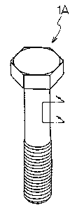
Figure 1(a) is a perspective view showing an embodiment of
the fastening member in accordance with an aspect of the present
invention, which is constituted as an external thread member.
Figure 1(b) is an enlarged perspective view showing part of the
external thread member of Figure 1(a).
Figure 2(a) is a perspective view showing a different
embodiment of the fastening member in accordance with an aspect
of the present invention, which is constituted as an internal
thread member. Figure 2(b) is an enlarged perspective view
showing part of the internal thread member of Figure 2(a).
With reference to Figures 1(a) and 1(b), an external thread
member 1A, which serves as an embodiment of the fastening member
in accordance with an aspect of the
present invention, is formed from a fibre-reinforced
ceramic composite material 20 (cf. Fig. 5), in which a
ceramic material 3 is reinforced with a plurality of
inorganic long fibres 2. The inorganic long fibres 2
are located in the ceramic material 3 such that first
orientated layers ZA in which the inorganic long fibres
2 are orientated in a first predetermined direction, and
second orientated layers 2B in which the inorganic long
fibres 2 are orientated in a second direction which is
different from the direction of orientation of the inorganic
long fibres 2 in the first orientated layers 2A may be
laminated alternately.
The outer shape of the external thread member
1A is the same as the outer shape of an ordinary known
external thread member.
11
CA 02166167 2001-10-30
In the external thread member 1A shown in
Figures 1(a) and 1(b), the direction (i.e., the
predetermined direction) of orientation of
the inorganic long fibres 2 in the first orientated
layers 2A should preferably fall within the range of 0
to 90' with respect to the longitudinal direction of
the external thread member 1A. In this embodiment, the
first orientated layers ZA are located such that the
longitudinal direction of each of the inorganic long
fibres 2 may be orientated in the 0' direction with
respect to the longitudinal direction of the external
thread member 1A.
Also, in the external thread member 1A shown
in Figures 1(a) and 1(b), the direction (i.e., the
different direction) of orientation of the
inorganic long fibres 2 in the second orientated layers
2B should preferably fall within the range of 0 to 90°
with respect to the width direction of the external
thread member 1A. In this embodiment, the second
orientated layers 2B are located such that the longitu-
dinal direction of each of the inorganic long fibres 2
may be orientated in the 0' direction with respect to
the width direction of the external thread member 1A.
In this embodiment, the first orientated
layers 2A and the second orientated layers 2B are
located in parallel with each other and along the
longitudinal direction of the external thread member
1A. Alternatively, the first orientated layers 2A and
12
CA 02166167 2001-10-30
the second orientated layexs 2B may be inclined respec-
tively at an angle falling within the range of 0.1 to
90' with respect to the longitudinal direction of the
external thread member 1A. In such cases, however, the
first orientated layers 2A and the second orientated
layers 2B which are laminated alternately should
preferably be in parallel.
In this embodiment, the first orientated
layers 2A and the second orientated layers 2B are
located such that the angle, at which the directions of
orientation in both layers intersect each other, may be
equal to 90'. However, in the external thread member
as shown in Figures 1(a) and 1(b>, the angle, at which
the directions of orientation in both layers intersect
each other, is not limited to 90° . The first
orientated layers 2A and the second orientated layers
2B may be located such that the angle, at which the
directions of orientation in both layers intersect each
other, may be 0 to 89.9'. The interval between a first
orientated layer 2A and the adjacent second orientated
layer 2B should preferably be 0.1 to 500 gym.
The external thread member serving as the embodiment
of the fastening member in accordance with an aspect of the
present invention is formed such that the
layers, in which the longitudinal direction of each of
the inorganic long fibres is orientated in the longitu-
dinal direction (i.e, thfe axial direction) of the
13
CA 02166167 2001-10-30
external thread member, and the layers, in which the
longitudinal direction of each of the inorganic long
fibres is orientated in the width direction (i.e, the
thread direction) of the external thread member, are
respectively present in the external thread member.
Therefore, the fastening member has a high strength with respect
to the tensile stress received in use and has a high shearing
force.
With reference to Figures 2(a) and 2(b), an internal thread
member 1B, which serves as a different embodiment of the
fastening member in accordance with an aspect of the present
invention, is formed from a fibre-reinforced ceramic composite
material 20, in which a ceramic material 3 is reinforced with a
plurality of inorganic long fibres 2. The inorganic long fibres
2 are located in the ceramic material 3 such that first
orientated layers 2A in which the inorganic long fibres 2 are
orientated in a first predetermined direction, and second
orientated layers 2B, in which the inorganic long fibres 2 are
orientated in a second direction which is different from the
direction of orientation of the inorganic long fibres 2 in the
first orientated layers 2A may be laminated alternately.
The outer shape of the internal thread member 1B is the same
as the outer shape of an ordinary known internal thread member.
In the internal thread member 1B shown in Figures 2(a) and
2(b), the direction of orientation of the inorganic long fibres
2 in the first orientated layers 2A should preferably fall within
llm ramie of 0
14
CA 02166167 2001-10-30
to 90° with respect to one diameter direction of the
internal thread member 1B (i.e., with respect to the
direction indicated by the arrow D in Figure 2(a)>. In
this embodiment, the first orientated layers 2A are
located such that the longitudinal direction of each of
the inorganic long fibres 2 may be orientated in the
0' direction with respect to the one diameter direction
of the internal thread member 1B.
Also, in the internal thread member 1B shown
in Figures 2(a> and 2(b), the direction of orientation
of the inorganic long fibres 2 in the second orientated
layers 2B is different from the direction of orienta-
tion of the inorganic long fibres 2 in the first orien-
tated layers 2A and should preferably fall within the
range of 0 to 90' with respect to the one diameter
direction of the internal thread member 1B. In this
embodiment, the second orientated layers 2B are located
such that the longitudinal direction of each of the
inorganic long fibres 2 may be orientated in the 90'
direction with respect to the one diameter direction of
the internal thread member 1B.
In this embodiment, the first orientated
layers 2A and the second orientated layers 2B are
located in parallel with each other and along the one
diameter direction of the internal thread member 1B.
IS
CA 02166167 2001-10-30
Alternatively, the first orientated layers 2A and the
second orientated layers 2B may be inclined
respectively at an angle falling within the,range of 0
to 90' with respect to the one diameter direction of
the internal thread member 1B. In such cases, however,
the first orientated layers 2A and the second
orientated layers 2B laminated alternately -should
preferably be in parallel.
In this embodiment, the first orientated
layers 2A and the second orientated layers 2B are
located such that the angle, at which the directions of
orientation in both layers intersect each other, maybe
equal to 90'. However, in the internal thread member
as shown in Figures 2(a) and 2(b), the angle, at which
the directions of orientation in both layers intersect
each other, is not limited to 90'. The first orientat-
ed layers 2A and the second orientated layers 2B should
preferably be located such that the angle, at which the
directions of orientation in both layers intersect each
other, may be 0 to 90' . The interval between a first
orientated layer 2A and the adjacent second orientated
layer 2B should preferably be 0.1 to 500 ~.m.
The internal thread member serving as the embodiment
of the fastening member in accordance with an aspect of the
present invention is formed such that the
16
CA 02166167 2001-10-30
layers, in which the longitudinal direction of each of the
inorganic long fibres is orientated in the 0° direction with
respect to the one diameter direction of the internal thread
member, and the layers, in which the longitudinal direction of
each of the inorganic long fibres is orientated in the 90°
direction with respect to one diameter direction (i.e., in the
thread direction) of the internal thread member, are respectively
present in the internal thread member. Therefore, the fastening
member has a high strength with respect to the compression stress
received in use and has a high shearing force.
In the embodiments described above, the fastening member in
accordance with an aspect of the present invention is constituted
as the external thread member and the internal thread member.
However, the fastening member in accordance with an aspect of the
present invention is not limited thereto. The fastening member
in accordance with an aspect of the present invention is also
applicable to, for example, shear pins, clevis pins, and screw
parts, e.g., washers.
An embodiment of the method of another aspect of this
invention for producing the fastening member in accordance with
an aspect of the present invention will be described hereinafter.
The method according to another aspect of this invention for
producing the fastening member in accordance with an aspect of
the present invention can be carried out by successively carrying
out steps (1), (2), and (3) described below.
(1) The step of embedding a plurality of inorganic long
fibres in a ceramic material such that the inorganic long fibres
may be orientated in a first predetermined direction, a plurality
of first preforms being thereby formed.
(2) The step of laminating the first preforms, which have
been obtained from the step (1), such that the directions of
orientation of the inorganic long fibres in adjacent preforms may
intersect each other at a predetermined angle, and sintering the
laminated preforms, a fibre-reinforced ceramic composite material
being thereby obtained.
(3) The step of cutting a piece with a predetermined
directivity from the obtained fibre-reinforced ceramic composite
17
CA 02166167 2001-10-30
material, and shaping the cut piece, the fastening member being
thereby obtained.
The steps (1), (2), and (3) will be described hereinbelow
with reference to Figures 3, 4, 5, and 6.
Figure 3 is a perspective view showing how the preforms
utilized for the fastening member in accordance with an aspect
of the present invention are laminated. Figure 4 is a perspective
view showing a fibre-reinforced ceramic composite material
utilized for the fastening member in accordance with an aspect
of the present invention. Figure 5 is a schematic perspective
view showing a direction, in which an external thread member
serving as an embodiment of the fastening member in accordance
with an aspect of the present invention is cut from the fibre-
reinforced ceramic composite material. Figure 6 is a schematic
perspective view showing a direction, in which an internal thread
member serving as an embodiment of the fastening member in
accordance with an aspect of the present invention is cut from
the fibre-reinforced ceramic composite material.
Though not shown, step (1) described above can be carried out
with a known method, except that the respective inorganic long
fibres are embedded in the ceramic material such that they may
be parallel with one another along the longitudinal direction of
each fibre and may form a straight line along the width direction
of each fibre, and such that the first orientated layer or layers
and the second orientated layer or layers can be formed.
Specifically, as the predetermined direction described above for
the step (1) , an arbitrary direction may be employed which is
parallel to the longitudinal direction of each of the inorganic
long fibres.
Step (2) described above can be carried out in the manner
shown in Figures 3 and 4. Specifically, firstly, as shown in
Figure 3, preforms 10 and preforms 10' having been obtained from
step (1) described above are laminated alternately such that the
directions of orientation of the inorganic long fibres 2 in
adjacent preforms 10 and 10' may intersect each other at an angle
(in Figure 3, 90°), which falls within the preferable range of
the angle of intersection described above. In this manner, a
18
CA 02166167 2001-10-30
laminate of the preforms 10 and preforms 10' is obtained.
Thereafter, the laminate is sintered, and a fibre-reinforced
ceramic composite material 20 shown in Figure 4 is thereby
obtained. In the fibre-reinforced ceramic composite material 20,
the first orientated layer or layers 2A in which the longitudinal
direction of each of the inorganic long fibres 2 is orientated
in a predetermined direction (i.e., in the direction indicated
by the arrow D1 in Figure 4), and the second orientated layer or
layers 2B in which the longitudinal direction of each of the
inorganic long fibres 2 is orientated in a direction (i.e., in
the direction indicated by the arrow D~ in Figure 4) which is
different from the direction of orientation of the inorganic long
fibres 2 in the first orientated layer or layers 2A, are
laminated alternately. The sintering may be carried out with an
HIP method, a hot
pressing method, or the like. Of these methods, the
HIP method is particularly preferable. With the HIP
method, the sintering may be carried out under the
conditions of a temperature of 900 to 2, 100' C, a pres-
sure of 50 to 3,000 kg/cm2, and a time span of 1 minute to
days. The term'."predetermined direction" and the
term "different direction" as used herein for the thus
obtained fibre-reinforced ceramic composite material 20
are the same as those described above.
Step (3> described above can be carried
out, for example, in the manner shown in Figure 5 or
Figure 6. Specifically, in cases where the external
thread member 1A described above is to be produced, as
illustrated in Figure 5, a piece having a circular
cylinder shape is cut along the D1 direction (i.e., the
horizontal direction with respect to the laminating
19
CA 02166167 2001-10-30
direction) from the fibre-reinforced ceramic composite
material 20. The cut piece (not shown) having the
circular cylinder shape-is then shaped into the exter-
nal thread member 1A.
The cutting can be carried out with
a cutting method or a grinding method.
The shaping of the external thread member may
be carried out with a wet type of grinding method using
a thread grinder, or the like. The shaping may be
carried out under the conditions of a wheel rotation
speed of 1,000 to 1,800 rpm, a depth of cut of 0.01 to
0.1 mm, and a workpiece rotation speed of 6 to 16 rpm.
In cases where the internal thread member 1B
described above is to be produced, as illustrated in
Figure 6, a piece having a circular cylinder shape is
cut along the D3 direction (i.e., the height direction
or the direction perpendicular to the aforesaid Dl or
D2 direction) from the fibre. reinforced ceramic compos-
ite material 20. The cut piece (not shown) having the
circular cylinder shape is then shaped into the inter-
nal thread member 1B.
The cutting can be carried out with
a cutting method or a grinding method.
The shaping of the internal thread member may
be carried out with a wet type of grinding method
using, for example, a three-axis simultaneous. control
milling machine fitted with an annular angular grinding
CA 02166167 2001-10-30
tool having no lead angle. The shaping may be carried
out under the conditions of'a spindle rotation speed of
6,000 to 12,000 rpm, a depth of cut of 0.01 to 0.05 mm,
and a feed rate of 100 to 150 mm/min.
The cutting of the piece for the
internal thread member 1H may be carried out along a
direction other than the D3 direction. In
such cases, it is necessary for the cutting direction to be such
that the angle 8 with respect to the D3 direction may be ~30° or
less. If the angle 8 is larger than ~30", peeling between
laminated layers will readily occur, and the strength required
for the member cannot be obtained sufficiently.
The present invention in its various aspects will further be
illustrated by the following nonlimitative examples.
Examples
The direction indicated by the arrow in Figure 3 was taken
as 0°, and preforms, in which the longitudinal direction of each
of inorganic long fibres was orientated in the 10° direction, and
preforms, in which the longitudinal direction of each of
inorganic long fibres was orientated in the 90° direction, were
laminated alternately. Thereafter, the thus obtained laminate was
sintered with the HIP method at a temperature of 1,300°C and a
pressure of 100 kg/cm2 for one hour. In this manner, a fibre-
reinforced ceramic composite material shown in Figure 4 was
obtained. In the fibre-reinforced ceramic composite material, the
product available under the trade-mark of TYRANNO FIBERTM and
supplied by Ube Industries, Ltd. was used as the inorganic long
fibres, and glass-ceramics having the composition of Ba0-Mg0-
A1203-Si02 was used as the
21
CA 02166167 2001-10-30
ceramic material.
A round bar stock was cut from the obtained
fibre-reinforced ceramic composite material. The
cutting was carried out in the horizontal direction
with respect to the ' laminating direction.
The round bar stock was then shaped, and the external
thread member (having a size of M10x40, 40 representing
the length under the head) shown in Figures 1(a> and
1(b) was thereby obtained.
Also, a fibre'-reinforced ceramic composite
material was obtained in the same manner as that de-
scribed above, and a round bar stock was cut from the
obtained fibre-reinforced ceramic composite material.
The cutting was carried out in the perpendicular direc-
tion with respect to the laminating direc-
tion. The round bar stock was then shaped, and the
internal thread member (having a size of M10x14, 14
representing the nut height) shown in Figures 2(a> and
2(b) was thereby obtained.
The shaping of the external thread member was
carried out with the grinding method. The grinding was
carried out with the wet method under the conditions of
a wheel rotation speed of 1,000 rpm, a depth ,of cut of
0.05 mm, and a workpiece rotation speed of 9.5 rpm.
The shaping of the internal thread member was
22
CA 02166167 2001-10-30
carried out with a wet method using a three-axis simul-
taneous control milling machine and an annular angular
grinding tool having no lead angle. The shaping was
carried out under the conditions of a spindle rotation
speed of 6,000 rpm, a depth of cut of 0.03 mm, and a
feed rate of 90 mm/min.
As for the obtained M10x1.5 external thread
member and internal thread member, tensile tests were
carried out and the loads at break were measured ac-
cording to MIL-STD1312. The load at break of the
external thread member was 13.7 KN (1,400kgf), and the
load at break of the internal thread member was 98 KN
(10,000 kgf>.
The measurement for the external
thread member was carried out by setting an internal
thread member, which was constituted of an alloy steel
(AISI4130) having a height of 10 mm, to the thread
portion of the external thread member. Also, the
measurement for the internal thread member
was carried out by setting an external thread member,
which was constituted of a bearing steel (SLJJ2) having
a thread length of 25 mm, to the internal thread member
having a height of 14 mm.
Comparative Example
For comparison, a bolt (thread size M10x1.5)
23
CA 02166167 2001-10-30
constituted of only Si3N4 was prepared. As for the
bolt, the tensile load at break was measured in the
same manner as that in the Examples described above.
The tensile load at break of the bolt was 3.8 kN (390
kgf ) .
24