Language selection

Search

Patent 2166424 Summary

Third-party information liability

Some of the information on this Web page has been provided by external sources. The Government of Canada is not responsible for the accuracy, reliability or currency of the information supplied by external sources. Users wishing to rely upon this information should consult directly with the source of the information. Content provided by external sources is not subject to official languages, privacy and accessibility requirements.

Claims and Abstract availability

Any discrepancies in the text and image of the Claims and Abstract are due to differing posting times. Text of the Claims and Abstract are posted:

  • At the time the application is open to public inspection;
  • At the time of issue of the patent (grant).
(12) Patent: (11) CA 2166424
(54) English Title: A SEED BRAKE
(54) French Title: BROYEUSE A GRAINS
Status: Expired and beyond the Period of Reversal
Bibliographic Data
(51) International Patent Classification (IPC):
  • A01C 7/20 (2006.01)
  • A01C 7/08 (2006.01)
(72) Inventors :
  • LONG, JOHN DAVID (United States of America)
(73) Owners :
  • DEERE & COMPANY
(71) Applicants :
  • DEERE & COMPANY (United States of America)
(74) Agent: BORDEN LADNER GERVAIS LLP
(74) Associate agent:
(45) Issued: 1999-10-12
(22) Filed Date: 1996-01-02
(41) Open to Public Inspection: 1996-09-16
Examination requested: 1996-01-02
Availability of licence: N/A
Dedicated to the Public: N/A
(25) Language of filing: English

Patent Cooperation Treaty (PCT): No

(30) Application Priority Data:
Application No. Country/Territory Date
08/404,775 (United States of America) 1995-03-15

Abstracts

English Abstract


A seed brake for a pneumatic agricultural seeding and/or
fertilizing machine. The seed brake comprises a curved tube
having an inner curved side and an outer curved side. The
inner curved side is provided with an opening. The inner
curved side is also provided with a baffle located between the
opening and the outlet of the tube. The baffle extends into
the tube and is integrally formed with the inner curved side.
The baffle is formed by kinking the tube.


Claims

Note: Claims are shown in the official language in which they were submitted.

The embodiments of the invention in which an exclusive
property or privilege is claimed are defined as follows:
1. A seed brake for an agricultural seeding machine
wherein particulate matter is delivered to a planting furrow
by an air stream, the seed brake comprising:
a tube having an inlet for receiving particulate matter
and an outlet for dispensing particulate matter, the tube is
provided with a curved portion located between the inlet and
the outlet, the curved portion is provided with an inner
curved side and an outer curved side;
the inner curved side is provided with an opening for
removing air from the tube; and
a baffle is positioned between the opening and the
outlet, the baffle extends from and is integrally formed with
the inner curved side.
2. A seed brake as defined by claim 1 wherein the baffle
is formed by kinking the tube.
3. A seed brake for an agricultural seeding machine
wherein particulate matter is delivered to a planting furrow
by an air stream, the seed brake comprising:
a tube having an inlet for receiving particulate matter
and an outlet for dispensing particulate matter, the tube is
provided with a curved portion located between the inlet and
the outlet, the curved portion is provided with an inner
curved side and an outer curved side;
the inner curved side is provided with an opening for
removing air from the tube; and
a baffle is positioned between the opening and the
outlet, the baffle is integrally formed with the inner curved
side.
4. A seed brake as defined by claim 3 wherein the baffle
is formed by kinking the tube.
5. A seed brake for an agricultural seeding machine
wherein particulate matter is delivered to a planting furrow
by an air stream, the seed brake comprising:
a tube having an inlet for receiving particulate matter
and an outlet for dispensing particulate matter, the tube is

provided with a curved portion located between the inlet and
the outlet, the curved portion is provided with an inner
curved side and an outer curved side;
the inner curved side is provided with an opening for
removing air from the tube; and
a baffle is positioned between the opening and the
outlet, the baffle is formed by kinking the tube.

Description

Note: Descriptions are shown in the official language in which they were submitted.


2166424
A SEED BRAKE
BACKGROUND OF THE INVENTION
1. Field of the Invention:
The present invention is directed to a seed brake for
reducing the speed of seed and/or fertilizer entrained in an
air stream.
2. Description of the Prior Art:
Large pneumatic seeding and fertilizing machines entrain
metered seed and fertilizer in high speed air streams before
directing it to a planting furrow. The high velocity of the
air stream may cause the seed and fertilizer to bounce or to
be blown out of the planting furrow. To overcome this problem
air brakes have been proposed to remove the pressurized air
and slow down the seed or fertilizer before it enters the
planting furrow.
One proposal is to provide an air diffuser upstream from
the planting furrow which comprises a perforated tube, see US
Patent 3,964,639. US Patent 5,392,722 discloses another type
of air diffuser used in a mini-hopper. Australian Patent
434,589 discloses a curved tube air diffuser having a
plurality of holes.
Dutch Industries Ltd. of Regina Saskatchewan, Canada,
markets a Dutch Seed Brake comprising an enlarged tube section
having a plurality of holes in which is located a baffle.
SUMMARY
It is an object of the present invention to provide a
seed brake for releasing pressurized air, wherein the flow and
passage of seed and/or fertilizer through the seed brake are
unhindered.
The present invention comprises a tube having an inlet
for receiving seed and/or fertilizer and an outlet for
dispensing seed and/or fertilizer from the tube. The tube has
a curved portion with an inner curved side and an outer curved
side. The inner curved side is provided with an opening for
releasing pressurized air from the tube. A baffle is provided
between the opening and the outlet on the inner curved side of
the tube. The baffle extends into the tube from the inner

- 21~6~2~
curved side. The baffle is integrally formed with the inner
curved side by kinking the tube.
BRIEF DESCRIPTION OF THE DRAWINGS
Figure 1 is a side view of an individual planting unit.
Figure 2 iS a side view of the seed brake of the present
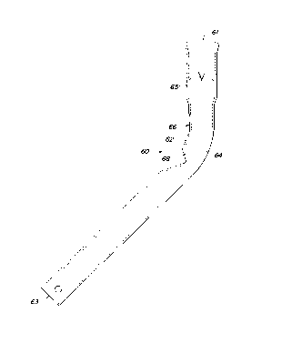
invention.
Figure 3 is a partial rear view of the seed brake of the
present invention.
DETAILED DESCRIPTION
Referring now to FIGURE 1, therein is shown an
agricultural seeding machine having a furrow opener assembly
10 supported from a frame member 12 of a grain drill or
similar seeding implement adapted for forward movement F over
a field. The furrow opener assembly 10 comprises an angled
opener disk 18 supported from a drawbar 22 for rotation about
an axis angled from the transverse direction. A seed boot 24
is supported closely adjacent the disk 18 in the shadow of the
leading edge of the disk. The seed boot 24 is provided with a
steel seed tube 2 6 which is connected to a metered source of
seeds (not shown).
A down-pressure spring assembly 32 biases the opener disk
18 into the soil to open a planting furrow 36. A depth
adjustment wheel 42 is supported for rotation adjacent the
leading side of the disk 18 about an axis offset from the axis
of the disk. Furrow depth is controlled with an adjustment
mechanism 44 which moves the axis of the wheel 42 vertically
with respect to the disk 18.
Seed lock wheel 51 and closing wheel 52 are supported
rearwardly adjacent the disk 18 from arms 53 and 54,
respectively. The seed lock wheel normally runs in the
planting furrow for pressing the seeds to the furrow providing
good seed-soil contact. The closing wheels crush the side of
the furrow thereby covering the seeds and providing
a loose layer of soil over the seeds. Seed locking and furrow
closing force may be adjusted by down-pressure spring
assemblies 55 and 56.

216~2~
_
The seed boot 24 is provided with a steel seed tube 26
that extends upwardly above the furrow opener lO. The seed
brake of the present invention is part of this tube. The seed
tube is provided with an inlet 61 for receiving seeds and/or
fertilizer and an outlet 63 for dispensing seeds and/or
fertilizer. The tube is further provided with a curved
portion 60 having a inner curved side 62 and an outer curved
side 64. The inlet portion of the seed tube is provided with
inwardly projecting tongs 65 for mounting a plastic seed tube
to the inlet portion.
An air opening 66 is formed in the inner curved side 62.
Seed as it is propelled through the tube by the high velocity
air stream gravitates to the outer curved side 64 of the seed
brake because of centrifugal force. Immediately downstream
from the opening 66 is a baffle 68 which causes a back
pressure effect in the tube upstream from the baffle so that
pressurized air is forced out the opening 66.
Baffle 68 extends approximately halfway into the tube
from the inside curved side. The baffle is integrally formed
with the inner curved side by kinking the tube. Another way of
forming the baffle would be to cut an angled slot in the tube
and insert and weld a plate in place to form the baffle. By
locating the baffle on the inside curved side the flow and
passage of seed and or fertilizer is left unhindered.
The above discussed invention can be used with all types
of particulate matter including seeds and/or fertilizer. As
such it should not be limited to the above described
embodiments, but should be limited solely by the claims that
follow.

Representative Drawing
A single figure which represents the drawing illustrating the invention.
Administrative Status

2024-08-01:As part of the Next Generation Patents (NGP) transition, the Canadian Patents Database (CPD) now contains a more detailed Event History, which replicates the Event Log of our new back-office solution.

Please note that "Inactive:" events refers to events no longer in use in our new back-office solution.

For a clearer understanding of the status of the application/patent presented on this page, the site Disclaimer , as well as the definitions for Patent , Event History , Maintenance Fee  and Payment History  should be consulted.

Event History

Description Date
Inactive: IPC from MCD 2006-03-12
Time Limit for Reversal Expired 2002-01-02
Letter Sent 2001-01-02
Grant by Issuance 1999-10-12
Inactive: Cover page published 1999-10-11
Inactive: Final fee received 1999-07-20
Pre-grant 1999-07-20
Notice of Allowance is Issued 1999-03-25
Letter Sent 1999-03-25
Inactive: Approved for allowance (AFA) 1999-02-18
Amendment Received - Voluntary Amendment 1998-07-09
Inactive: S.30(2) Rules - Examiner requisition 1998-05-15
Inactive: Status info is complete as of Log entry date 1997-12-29
Inactive: Application prosecuted on TS as of Log entry date 1997-12-29
Application Published (Open to Public Inspection) 1996-09-16
All Requirements for Examination Determined Compliant 1996-01-02
Request for Examination Requirements Determined Compliant 1996-01-02

Abandonment History

There is no abandonment history.

Maintenance Fee

The last payment was received on 1998-12-31

Note : If the full payment has not been received on or before the date indicated, a further fee may be required which may be one of the following

  • the reinstatement fee;
  • the late payment fee; or
  • additional fee to reverse deemed expiry.

Please refer to the CIPO Patent Fees web page to see all current fee amounts.

Fee History

Fee Type Anniversary Year Due Date Paid Date
Request for examination - standard 1996-01-02
MF (application, 2nd anniv.) - standard 02 1998-01-02 1997-12-31
MF (application, 3rd anniv.) - standard 03 1999-01-04 1998-12-31
Final fee - standard 1999-07-20
MF (patent, 4th anniv.) - standard 2000-01-04 1999-12-30
Owners on Record

Note: Records showing the ownership history in alphabetical order.

Current Owners on Record
DEERE & COMPANY
Past Owners on Record
JOHN DAVID LONG
Past Owners that do not appear in the "Owners on Record" listing will appear in other documentation within the application.
Documents

To view selected files, please enter reCAPTCHA code :


To view images, click a link in the Document Description column. To download the documents, select one or more checkboxes in the first column and then click the "Download Selected in PDF format (Zip Archive)" or the "Download Selected as Single PDF" button.

List of published and non-published patent-specific documents on the CPD .

If you have any difficulty accessing content, you can call the Client Service Centre at 1-866-997-1936 or send them an e-mail at CIPO Client Service Centre.


Document
Description 
Date
(yyyy-mm-dd) 
Number of pages   Size of Image (KB) 
Claims 1998-07-09 2 56
Cover Page 1996-04-25 1 15
Claims 1996-04-25 1 32
Description 1996-04-25 3 139
Drawings 1996-04-25 2 47
Abstract 1996-04-25 1 13
Representative drawing 1998-01-29 1 12
Representative drawing 1999-10-04 1 4
Cover Page 1999-10-04 1 24
Reminder of maintenance fee due 1997-09-03 1 111
Commissioner's Notice - Application Found Allowable 1999-03-25 1 164
Maintenance Fee Notice 2001-01-30 1 176
Correspondence 1999-07-20 1 28