Note: Descriptions are shown in the official language in which they were submitted.
~1~G~~~
1
The invention relates to a machine for implementing track
maintenance operations, comprising a machine frame, supported
on on-track undercarriages, which has a first work section
located between two on-track undercarriages and a second work
section immediately following it in the longitudinal direction
of the machine, and guide rails arranged on the machine frame
and extending in the longitudinal direction of the machine for
the displacement of a transporting device designed to be self-
propelled by means of a drive.
A track maintenance machine of this kind is already known
through US 5,193,461, this machine being used to exchange
sleepers of a track and being provided with a machine frame
designed for mobility by means of on-track undercarriages.
This machine frame is subdivided into two work sections, one
following the other, the first of which is located between the
two on-track undercarriages; coordinated with this section,
in its upper region, is an opening in the machine frame. The
second work section immediately following it is provided with
guide rails on which is mounted a transporting device in the
form of a sleeper crane designed to be self-propelled in the
longitudinal direction of the machine. Furthermore, the guide
rails extend over sleeper transport wagons coupled to the
machine, on which old and new sleepers are deposited. These
are now transported to and fro between the wagons and the
first work section by means of the crane and are passed
through the opening in the machine frame, beneath which is
located a depositing device associated with the sleeper
exchange device.
A wagon for laying or taking up track panels is known
~~~~43~
2
through FR 2 378 898. This wagon has a machine frame
supported at each end on on-track undercarriages, on top of
which is a superstructure which is arched in the transverse
direction of the wagon. This superstructure projects at both
longitudinal ends over the respective on-track undercarriages
and in the upper end region is connected to guide rails
extending in the longitudinal direction of the wagon. Track
panels may be moved over the entire length of the
superstructure in the longitudinal direction of the wagon
using sliding carriages displaceably mounted on the said guide
rails.
The object of the present invention is now to provide a
machine of the type specified in the introduction which is
particularly suitable for use in track maintenance operations
in switch and crossing regions.
This object is achieved with a machine of the type
previously defined in that the machine frame in the first work
section is essentially composed of two longitudinal frame
beams extending parallel to one another and in the
longitudinal direction of the machine and at a distance from
one another in the transverse direction of the machine, the
said longitudinal frame beams being connected to one another
in the region between the on-track undercarriages solely by a
transverse connection provided above the guide rails, and in
that the transporting device is designed to travel from the
second work section underneath the transverse connection into
the first work section.
A track maintenance machine designed in this way
advantageously now enables even bulky or oversized track
elements, required when inserting and relaying switches and
the like, to be handled in an entirely problem-free manner in
the course of operational use. Such elements may be delivered
by means of the transporting device from a coupled loading
wagon, for instance, and be transported via the guide rails
CA 02166438 2004-12-13
3
right to the insertion site, which is located beneath the
first work section. Subsequent manoeuvring of the track
elements into the desired, correct position becomes
particularly easy as a result of the special design of the
machine frame, as in the lower region thereof the longitudinal
frame beams have no transverse connection and therefore there
is nothing to restrict the freedom of movement or,
advantageously, the clear view of the worksite beneath the
guide rails. However, the transverse connection disposed
above the guide rails does ensure, in spite of this optimum
free space, that the necessary torsional strength of the
machine frame is retained even when the first work section is
extended to a maximum through the on-track undercarriages
being placed a considerable distance apart. This in turn
provides the advantage - specifically in connection with a
further development according to which the two longitudinal
frame beams in the first work section are designed so as to be
upwardly recessed, and the transverse connection is provided
in the upper end region of the longitudinal frame beams - of
creating space for additional work units or more freedom of
movement for the operating personnel.
A further development, in which the guide rails are arranged
both in the first and in the second work section in a plane
located immediately above the on-track undercarriages, ensures
optimum mobility of the transporting device which is also
provided with an advantageously large operating range to deal
with the various operational situations occurring in practice.
In a further feature, there is provided at the more remote end
of the machine frame from the second work section an operator's
cab with an access located between the two longitudinal frame
beams, which proves to be useful in enabling the operating
personnel to have a rapid and above all protected access to the
track worksite without the possibility of being put at risk by
any train traffic on an adjacent track.
According to additional variants, it is possible to adapt the
track maintenance machine to suit various operating conditions
or transport requirements, if necessary, while a further
embodiment represents the advantageous inclusion of the machine
according to the invention in a larger installation for track
~1~~~~~~
4
maintenance operations.
The invention is described in more detail in the
following with the aid of the drawings, in which
Fig. 1 and 2 show a side view of a machine for
implementing track maintenance operations - shown in two
parts for reasons of space,
Fig. 3 shows an enlarged sectional view of the machine
in the direction of arrow III in Fig. 1, and
Fig. 4, 5, and 6 show a schematic side view of an
installation for the implementation of track maintenance
operations which includes the aforementioned machine.
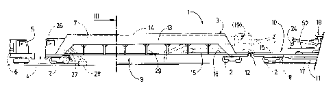
The machine 1 shown in Fig. 1 and 2 or 3 has a machine
frame 3 mounted on on-track undercarriages 2 and is designed
for mobility on a track 4 in order to implement track
maintenance operations. One end of the machine frame 3 is
coupled with a drive vehicle 5 on which a central energy
source 6 is located for supplying all the drives of the
machine 1 with energy.
Because of its great length, the machine frame 3 is
subdivided into two frame parts 7,8, arranged one following
the other in the longitudinal direction of the machine and
joined together in an articulated manner. The frame part 7
immediately adjoining the drive vehicle 5 forms a first work
section 9 in a region located between two on-track
undercarriages 2, while the region immediately following the
said first work section in the longitudinal direction of the
machine and extending over the frame part 8 is defined as the
second work section 10. In the present exemplary embodiment,
the frame part 8 is designed as a platform wagon 11 supported
on two separate on-track undercarriages 2 and releasably
connected to the other frame part 7 by means of a coupling 12.
~~~~43~
The frame part 7 of the machine frame 3 forming the first
work section 9 is essentially composed of two longitudinal
frame beams 13 which extend parallel to one another in the
longitudinal direction of the machine, and which are at a
distance from one another in the transverse direction of the
machine and are shaped so as to be upwardly recessed in the
region of the first work section 9. As is clear from Fig. 3,
the two longitudinal frame beams 13 are connected to one
another in this region located between the on-track
undercarriages 2 exclusively by a transverse connection 14
which is provided in the upper end region of the longitudinal
frame beams 13. Disposed at the more remote end of the
machine frame 3 from the second work section 10 is an
operator's cab 26 which is provided with an access 27 to the
working area or to the track 4, the said access being located
between the two longitudinal frame beams 13.
The machine frame 3 has, furthermore, a pair of guide
rails 15 which extend in the longitudinal direction of the
machine over the first and second work section 9,10 and which
are disposed in a plane 16 located immediately above the on-
track undercarriages 2, this plane coinciding with the loading
surface 17 of the platform wagon 11, and the guide rails 15
lying on top of the loading surface I7 in the region of the
second work section 10. In the region of the first work
section 9 or of the recessed frame part 7 the guide rails I5
are connected to the longitudinal frame beams 13 by means of
vertical supports 29 - arranged so as to be spaced uniform
distances apart in the longitudinal direction of the machine.
The horizontal distance apart of the two guide rails 15
approximately corresponds to the distance apart of the two
longitudinal frame beams 13 (Fig. 3).
Mounted on the guide rails 15 is a transporting device
18, designed to be self-propelled, which is equipped with a
drive 51 and by means of this is displaceable underneath the
transverse connection 14 of the longitudinal frame beams 13 -
216~4~~
6
the said transverse connection being provided above the guide
rails 15 - from the second work section 10 into the first work
section 9. The transporting device I8 is designed as a gantry
crane 19 which has on-track undercarriages 20 as well as a
driver's cab 21 at each longitudinal end 23, in which
respective central control units 22 are disposed.
Furthermore, the transporting device 18 is provided with two
gripping devices 24, each projecting in the longitudinal
direction of the machine over one longitudinal end 23 of the
gantry crane 19 and designed so as to be respectively
vertically and laterally adjustable by means of drives 25, and
being provided for picking up and transporting track parts.
Alternatively, it would of course also be possible to attach
the guide rails 15 to the underside of the transverse
connection 14, for instance, and to displace the transporting
device 18 along the guide rails 15 in a suspended fashion.
It is clear in Fig. 3 that a rail part 52 of a switch
section which is to be transported may be positioned between
the underside of the driver's cab 21 and the plane of the
guide rails 15. For the sake of simplicity the gripping
devices 24 carrying the guide rails 15 are not shown.
In operational use, the machine 1 is driven to the track
worksite by means of the drive vehicle 5 and is positioned in
such a way that the first work section 9 of the machine frame
3 is located over the site in the track 4 to be treated. With
the aid of the gantry crane 19 which is designed to travel
virtually over the entire length of the machine 1, the rail
parts 52 to be exchanged or required for insertion into the
track are transported to and fro between the first work
section 9 and the platform wagon 11 - serving to store
materials - of the second work section 10. Because of the
tunnel-like design of the frame part 7, forming the first work
section 9, above the guide rails 15, the gantry crane 19 may
be moved without hindrance over the whole working area, while
at the same time the gripping devices 24 may be pivoted
~16~~~
7
unrestrictedly both downwards as well as sideways on the track
level and may thus be used in a variety of ways. Also, hand
tools etc. may be brought to the worksite by the operating
personnel via the access 27 from the operator's cab 26.
However, it would also be conceivable for a work unit, such as
a rail welding unit 28 for example (indicated by dot and dash
lines), to be arranged in this region so as to be vertically
and laterally adjustable and for it to be moved into operation
in association with the transporting device 18. It is of
particular advantage that throughout the handling procedure of
the track parts to be taken away or inserted, the clearance
gauge does not have to be exceeded.
Shown schematically in Fig. 4 to 6 is an installation 30
for implementing various track maintenance operations, which
is designed for mobility on the track 4 in a working direction
indicated by an arrow 31. The installation 30 which is
designed specifically for the rapid renewal of rail sections
consists of several vehicles, arranged one following the other
in the longitudinal direction of the track and each designed
to be self-propelled by means of its own motive drive 32, and
the machine 1 already illustrated in Fig. 1 to 3 together with
the drive vehicle 5.
Shown at the front end of the installation 30 in the
working direction (Fig. 4) is a loading wagon 33 which is
provided at its rear end with a loading ramp 34 designed for
pivoting upwards. By means of this loading ramp individual
work machines transported on the loading wagon 33 and having
flanged rollers may be set on the track 4, these being a rail
spike puller 35, a sleeper anchor remover 36, a clip remover
37, a rail cutter 38 and a rail web grinder 39. The loading
wagon 33 is followed by the machine 1 described above with the
platform wagon 11 and the transporting device 18 mounted on
the guide rails 15 (Fig. 5).
The machine 1 is followed in the working direction by an
~1~~438
independently mobile welding machine 40 with a vertically
adjustable welding unit 41 (Fig. 6), this being followed by a
vehicle 42 on which are located a rail pulling device 43, a
crane jib 44 provided for positioning the same, as well as a
rail head grinding unit 45. A further loading wagon 46 with
loading ramp 47 forms the end of the installation 30, on which
separate machines, again provided with flanged rollers, are
transported - such as a rail spiking machine 48, a sleeper
anchor inserting machine 49 and a clip inserting machine 50.
All the operations required in exchanging rail parts may
be implemented with this installation 30 in the operational
use thereof.