Language selection

Search

Patent 2166449 Summary

Third-party information liability

Some of the information on this Web page has been provided by external sources. The Government of Canada is not responsible for the accuracy, reliability or currency of the information supplied by external sources. Users wishing to rely upon this information should consult directly with the source of the information. Content provided by external sources is not subject to official languages, privacy and accessibility requirements.

Claims and Abstract availability

Any discrepancies in the text and image of the Claims and Abstract are due to differing posting times. Text of the Claims and Abstract are posted:

  • At the time the application is open to public inspection;
  • At the time of issue of the patent (grant).
(12) Patent: (11) CA 2166449
(54) English Title: REAL ESTATE ELECTRO TAPE
(54) French Title: APPAREIL DE MESURE ELECTRONIQUE POUR L'IMMOBILIER
Status: Expired and beyond the Period of Reversal
Bibliographic Data
(51) International Patent Classification (IPC):
  • G01B 11/02 (2006.01)
  • G01B 21/02 (2006.01)
(72) Inventors :
  • THOMSON, CHRISTOPHER STUART (United States of America)
(73) Owners :
  • CHRISTOPHER STUART THOMSON
(71) Applicants :
(74) Agent: OSLER, HOSKIN & HARCOURT LLP
(74) Associate agent:
(45) Issued: 1999-12-21
(22) Filed Date: 1996-01-02
(41) Open to Public Inspection: 1996-07-10
Examination requested: 1997-12-30
Availability of licence: Yes
Dedicated to the Public: N/A
(25) Language of filing: English

Patent Cooperation Treaty (PCT): No

(30) Application Priority Data:
Application No. Country/Territory Date
08/370,519 (United States of America) 1995-01-09

Abstracts

English Abstract


A real estate electro tape is provided that measures
the length of an interior or exterior wall or other similar
structure using optical means. A sonic tape is used to measure
the perpendicular distance from the device to the interior or
exterior wall. Two steerable lasers are then used to determine
the angles between the perpendicular and the beams aimed at the
wall edges. An algorithm is applied to the angular and
perpendicular distance data to obtain the length of the wall.
A microprocessor performs the calculations, the results of
which are displayed on an electro optical display.


Claims

Note: Claims are shown in the official language in which they were submitted.

THE EMBODIMENTS OF THE INVENTION IN WHICH AN EXCLUSIVE
PROPERTY OR PRIVILEGE IS CLAIMED ARE DEFINED AS FOLLOWS:
1. A real estate electro tape, comprising:
a. a sonic tape wherein said sonic tape is a
conventional ultrasonic laser ranging device whose output is
the perpendicular distance (H) to a wall whose length is to be
measured:
b. a first steerable laser, mounted in close
proximity to said sonic tape, wherein the light beam from said
first steerable laser is aimed at one edge of said wall, such
that the angle (e1) between said light beam and said
perpendicular can be determined; and
c. a second steerable laser, mounted in close
proximity to said sonic tape, wherein the light beam from said
second steerable laser is aimed at the opposite edge of said
wall, such that the angle (e2) between said light beam and said
perpendicular can be determined; so that the total length of
the wall, LT can be determined by the formula: LT = H tan e1 +
H tan e2 + 2L' where L' is the distance, if any, between said
sonic tape and each of said steerable lasers.
2. A real estate electro tape, as recited in claim
1, wherein said first and second steerable lasers have visible
beams, and wherein said beams are aimed at corners or edges of
said walls by observing the reflection of light off said
corners when said steerable lasers are properly aimed.
3. A real estate electro tape, as recited in claim
1, further comprising calculating and display means for
outputting said total length as determined by the formula: LT
= H tan e1 + H tan e2 + 2 L'.
4. A real estate electro tape, as recited in claim
3, wherein said calculating means comprises:
a. a potentiometer attached to said first steerable

laser such that the output of said potentiometer is
proportional to the angle between said first steerable laser
and the perpendicular;
b. a potentiometer attached to said second
steerable laser such that the output of said potentiometer is
proportional to the angle between said second steerable laser
and the perpendicular;
c. a memory containing the algorithm: LT = H tan e1
+ H tan e2 + 2L' ; and
d. a microprocessor whose data inputs are the
outputs of each of said potentiometers and the output of said
sonic tape, wherein said microprocessor has as its output the
total length LT.
5. A real estate electro tape, as recited in claim
4, wherein said output of said microprocessor further comprises
the perpendicular distance to the wall (H), the angle (e1) and
the angle (e2).
6. A real estate electro tape, as recited in claim
3, wherein said display means comprises a liquid crystal
display (LCD) showing at least total distance LT.
7. A real estate electro tape, as recited in claim
3, wherein said display means comprises a light emitting diode
display (LED) showing at least total distance LT.
8. A real estate electro tape, as recited in claim
3, further comprising a power switch to turn said calculating
and display means on and off.
9. A real estate electro tape, as recited in claim
3, further comprising a calculate button to reset said
microprocessor and initiate processing according to said
algorithm.

10. A real estate electro tape, as recited in claim
3, further comprising laser locking/release buttons, attached
to each of said steerable lasers, such that said steerable
lasers can be locked into any position and can only be adjusted
when said locking/release buttons are in unlocked positions.

Description

Note: Descriptions are shown in the official language in which they were submitted.


~ibb44~
REAL ESTATE ELECTRO TAPE
BACKGROUND OF THE INVENTION
The instant invention relates, generally, to the
field of measurement instruments, and, more specifically, to
devices that measure the length of an interior or exterior wall
by indirect optical means.
In many fields of endeavor, such as real estate
appraisal, architecture, engineering, and building inspection,
it is necessary to measure the length of an interior or
exterior wall. It is often difficult to get close enough to
the wall to use, for instance, a measuring tape due to
obstructions, vegetation, or jags in the direction of the wall.
A number of measuring solutions have been suggested.
M. Fox (U.S. Patent 3,908,281) suggests a real estate appraisal
instrument and method. However, this instrument requires that
an object of known dimension be observed and such an object is
not always available. R. Genho (U. S. Patent 3,897,637)
proposes a laser level and square that does not provide any
measuring means but merely provides a laser-generated line that
defines a level. J. Rando (U.S. Patent 5,287,627) provides an
automatic plumb and level tool with acoustic measuring
capability. This device is very useful in providing a means
for measuring the distance to a laser-illuminated object but
does not provide means for measuring the length of the object
itself.
SUMMARY OF THE INVENTION
It is, therefore, a primary object of the present
invention to provide a real estate electro tape that can be
used to measure the length of an interior or exterior wall
without direct contact with the wall.
1

2166~4~
A further object is to provide a real estate electro
tape which uses optical methods to measure the length of an
interior or exterior wall.
Another object is to provide a real estate electro
tape which measures the length of an interior or exterior wall
with a fairly high degree of accuracy.
A further obj ect is to provide a real estate electro
tape which measures the length of an interior or exterior wall
quickly and with little training.
A further object is to provide a real estate electro
tape which is simple and inexpensive to fabricate.
A yet further object is to provide a real estate
electro tape that has an easy to read display.
To the accomplishment of the above and related
objects, this invention may be embodied in the form illustrated
in the accompanying drawings, attention being called to the
fact, however, that the drawings are illustrative only and that
changes may be made in the specific construction illustrated
and described within the scope of the appended claims.
BRIEF DESCRIPTION OF THE DRAWING FIGURES
The Figures in the drawings are briefly described as
follows:
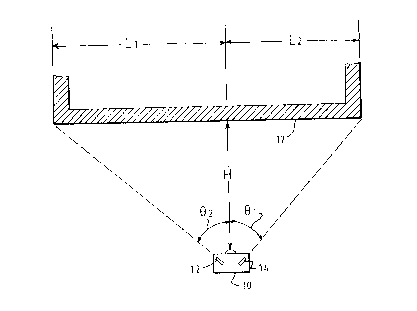
Figure 1 is a diagrammatic view of the invention
shown in use measuring the length of a wall:
2

~i66449
Figure 2 illustrates the algorithm used by the
invention;
Figure 3 is a front view of the invention;
Figure 4 is a top view of the invention showing the
controls and display thereof; and
Figure 5 is an electronic block diagram of the
invention.
DETAILED DESCRIPTION OF THE PREFERRED EMBODIMENTS
Figure 1 illustrates the real estate electro tape 10
in actual use. The wall to be measured is numeral 17. In use,
a sonic tape 16 is aimed at wall 17 to establish the distance
between the invention 10 and the wall 17. Sonic tape 16 is a
conventional technology already in use and available from
various sources. The output of the sonic tape 16 is the
perpendicular distance (H) from the wall 17. Next, steerable
laser 12 is aimed at one corner of the wall. The user can
confirm that the laser is hitting the edge or corner of the
wall by observing the reflection of the laser. The beam from
12 makes an angle (sz) with the perpendicular. Similarly,
steerable laser 14 is aimed at the opposite wall edge or corner
to determine angle (s~). Note that e~ and e2 are typically not
equal. Since the steerable lasers 12 and 14 are not exactly
coincident with the sonic tape 16, the displacement L' from
sonic tape 16 must be taken into consideration. The total
length of the wall 17 is determined, then, according to the
following formula (see Fig. 2):
LT = H tan e~ + H tan ez + 2L' .
3

166448
The physical layout of the invention can best be
understood with reference to Figures 3 and 4. Sonic tape 16
is centrally mounted on the front of 10. Steerable lasers 12
and 14 are mounted at equal distances from sonic tape 16 and
are mounted so as to allow the beams to scan in the horizontal
plane. Laser steering knob/potentiometer 18 is used to adjust
the horizontal position of steerable laser 14 and laser
steering knob/potentiometer 20 is used to adjust the horizontal
position of steerable laser 12. The steering knobs are locked
and released using laser locking/release buttons 22 and 30.
Power to 10 is turned on and off using on/off power switch 26.
When the distance measurement is desired, calculate button 28
is depressed causing information to be shown on display 24.
The electronic operation of the invention is best
understood with reference to Figure 5. Microprocessor 34
processes data from a number of sources according to algorithm
32. The inputs include: the output e~ of laser steering knob/
potentiometer 18, the output ez of laser steering knob/
potentiometer 20, and the output H of sonic tape 16. The
output of microprocessor 34 is input to display 24, which is
typically a liquid crystal display (LCD) or a light emitting
diode display (LED). The information displayed includes LT
and, optionally H, e~, and e2.
While certain novel features of this invention have
been shown and described and are pointed out in the annexed
claims, it will be understood that various omissions,
substitutions and changes in the forms and the details of the
device illustrated and in its operation can be made by those
skilled in the art without departing from the spirit of the
invention.
4

Representative Drawing
A single figure which represents the drawing illustrating the invention.
Administrative Status

2024-08-01:As part of the Next Generation Patents (NGP) transition, the Canadian Patents Database (CPD) now contains a more detailed Event History, which replicates the Event Log of our new back-office solution.

Please note that "Inactive:" events refers to events no longer in use in our new back-office solution.

For a clearer understanding of the status of the application/patent presented on this page, the site Disclaimer , as well as the definitions for Patent , Event History , Maintenance Fee  and Payment History  should be consulted.

Event History

Description Date
Inactive: Agents merged 2013-10-23
Inactive: IPC from MCD 2006-03-12
Time Limit for Reversal Expired 2004-01-02
Letter Sent 2003-01-02
Grant by Issuance 1999-12-21
Inactive: Cover page published 1999-12-20
Inactive: Final fee received 1999-09-15
Pre-grant 1999-09-15
Publish Open to Licence Request 1999-09-15
Letter Sent 1999-06-09
Notice of Allowance is Issued 1999-06-09
Inactive: Approved for allowance (AFA) 1999-05-12
Amendment Received - Voluntary Amendment 1998-04-23
Inactive: Application prosecuted on TS as of Log entry date 1998-02-10
Letter Sent 1998-02-10
Inactive: Status info is complete as of Log entry date 1998-02-10
All Requirements for Examination Determined Compliant 1997-12-30
Request for Examination Requirements Determined Compliant 1997-12-30
Application Published (Open to Public Inspection) 1996-07-10

Abandonment History

There is no abandonment history.

Maintenance Fee

The last payment was received on 1998-12-30

Note : If the full payment has not been received on or before the date indicated, a further fee may be required which may be one of the following

  • the reinstatement fee;
  • the late payment fee; or
  • additional fee to reverse deemed expiry.

Please refer to the CIPO Patent Fees web page to see all current fee amounts.

Fee History

Fee Type Anniversary Year Due Date Paid Date
MF (application, 2nd anniv.) - small 02 1998-01-02 1997-12-30
Request for examination - small 1997-12-30
MF (application, 3rd anniv.) - small 03 1999-01-04 1998-12-30
Final fee - small 1999-09-15
MF (patent, 4th anniv.) - small 2000-01-04 1999-12-29
MF (patent, 5th anniv.) - small 2001-01-02 2000-12-19
MF (patent, 6th anniv.) - small 2002-01-02 2001-12-19
Owners on Record

Note: Records showing the ownership history in alphabetical order.

Current Owners on Record
CHRISTOPHER STUART THOMSON
Past Owners on Record
None
Past Owners that do not appear in the "Owners on Record" listing will appear in other documentation within the application.
Documents

To view selected files, please enter reCAPTCHA code :


To view images, click a link in the Document Description column. To download the documents, select one or more checkboxes in the first column and then click the "Download Selected in PDF format (Zip Archive)" or the "Download Selected as Single PDF" button.

List of published and non-published patent-specific documents on the CPD .

If you have any difficulty accessing content, you can call the Client Service Centre at 1-866-997-1936 or send them an e-mail at CIPO Client Service Centre.


Document
Description 
Date
(yyyy-mm-dd) 
Number of pages   Size of Image (KB) 
Description 1996-04-25 5 165
Abstract 1996-04-25 1 18
Drawings 1996-04-25 2 42
Cover Page 1996-04-25 1 16
Claims 1996-04-25 3 100
Representative drawing 1998-04-01 1 9
Representative drawing 1999-12-07 1 6
Abstract 1998-02-17 1 17
Description 1998-02-17 4 154
Claims 1998-02-17 3 91
Cover Page 1999-12-07 1 30
Reminder of maintenance fee due 1997-09-03 1 111
Acknowledgement of Request for Examination 1998-02-10 1 179
Commissioner's Notice - Application Found Allowable 1999-06-09 1 165
Maintenance Fee Notice 2003-01-30 1 174
Correspondence 1999-09-15 1 63
Correspondence 1996-02-09 14 464
Fees 1998-12-30 1 59
Fees 1999-12-29 1 59
Fees 2001-12-19 1 57
Fees 1997-02-18 1 59
Fees 1997-12-30 1 61
Fees 2000-12-19 1 56