Language selection

Search

Patent 2166842 Summary

Third-party information liability

Some of the information on this Web page has been provided by external sources. The Government of Canada is not responsible for the accuracy, reliability or currency of the information supplied by external sources. Users wishing to rely upon this information should consult directly with the source of the information. Content provided by external sources is not subject to official languages, privacy and accessibility requirements.

Claims and Abstract availability

Any discrepancies in the text and image of the Claims and Abstract are due to differing posting times. Text of the Claims and Abstract are posted:

  • At the time the application is open to public inspection;
  • At the time of issue of the patent (grant).
(12) Patent Application: (11) CA 2166842
(54) English Title: ANGLED PLATES FOR CONNECTING DUCTS
(54) French Title: CORNIERES DE RACCORDEMENT DE CONDUITS D'AIR
Status: Deemed Abandoned and Beyond the Period of Reinstatement - Pending Response to Notice of Disregarded Communication
Bibliographic Data
(51) International Patent Classification (IPC):
  • F16L 23/14 (2006.01)
  • F24F 13/02 (2006.01)
(72) Inventors :
  • TIBERIO, JOSEPH W. (United States of America)
(73) Owners :
  • CENTURY MANUFACTURING CO., INC.
(71) Applicants :
  • CENTURY MANUFACTURING CO., INC. (United States of America)
(74) Agent: RICHES, MCKENZIE & HERBERT LLP
(74) Associate agent:
(45) Issued:
(22) Filed Date: 1996-01-09
(41) Open to Public Inspection: 1996-07-18
Availability of licence: N/A
Dedicated to the Public: N/A
(25) Language of filing: English

Patent Cooperation Treaty (PCT): No

(30) Application Priority Data:
Application No. Country/Territory Date
08/373,336 (United States of America) 1995-01-17

Abstracts

English Abstract


An angular plate for connecting channel shaped flanges
at the ends of ducts and including first and second legs each
having substantially planar top and bottom surfaces and with an
inner end portion of the first leg joined to an inner end portion
of the second leg so as to establish an angle therebetween. Defined
by the inner end portions is an opening for receiving a connector,
the first leg has substantially parallel inner and outer edges
extending between an outer end portion thereof and its inner end
portion and the second leg similarly has substantially parallel
inner and outer edges extending between an outer end portion thereof
and its inner end portion. The outer end portion of the first leg
defines structure projecting extending transversely from at least
one of the inner and outer edges of at least one of the first and
second legs. The projection engages a side wall portion of the
duct's transverse flange to retain the plate in a desired position
prior to crimping of the flange.


Claims

Note: Claims are shown in the official language in which they were submitted.

-8-
CLAIMS
1. An angular plate for connecting together channel
shaped flanges at the ends of ducts, said angular plate including
first and second legs each having substantially planar top and
bottom surfaces, an inner end portion of said first leg being
joined to an inner end portion of said second leg so as to
establish an angle between said first and second legs; and wherein
said inner end portions define an opening for receiving a connector,
said first leg has substantially parallel and rectilinear inner and
outer edges extending between an outer end portion thereof and said
inner end portion of said first leg, said second leg has sub-
stantially parallel and rectilinear inner and outer edges extending
between an outer end portion thereof and said inner end portion of
said second leg, and said outer end portion of at least one of
said first and second legs defines projection means projecting in
a direction substantially parallel to said planar top and bottom
surfaces and beyond at least one of said inner and outer edges of
said at least one of said first and second legs.
2. An angular plate according to claim 1 wherein said
projection means project transversely from each of said inner and
outer edges of said at least one of said first and second legs.
3. An angular plate according to claim 2 wherein said
projection means comprise transversely projecting teeth.

-9-
4. An angular plate according to claim 3 wherein said
teeth have pointed outer ends.
5. An angular plate according to claim 4 wherein said
outer end portion of said at least one of said first and second legs
defines a plurality of said teeth transversely projecting beyond
each of said inner and outer edges thereof.
6. An angular plate according to claim 5 wherein said
teeth project beyond said inner and outer edges by a distance
of between .003 and .010 inches.
7. An angular plate according to claim 6 wherein said
projection means projects transversely from each of first and
second legs.
8. An angular plate according to claim 1 wherein said
projection means projects in a direction substantially parallel
to said planar top and bottom surfaces and beyond at least one of
said inner and outer edges of each of said first and second legs.
9. An angular plate according to claim 8 wherein said
projection means project transversely beyond each of said inner
and outer edges of each of said first and second legs.
10. An angular plate according to claim 9 wherein said
projection means comprise transversely projecting teeth.
11. An angular plate according to claim 10 wherein
said teeth have pointed outer ends.

-10-
12. An angular plate according to claim 11 wherein
said teeth project from said inner and outer edges by a distance
of between .003 and .010 inches.
13. An angular plate according to claim 1 wherein said
projection means comprise transversely projecting teeth.
14. An angular plate according to claim 13 wherein said
teeth have pointed outer ends.
15. An angular plate according to claim 14 wherein said
teeth project from said inner and outer edges by a distance of
between .003 and .010 inches.
16. An angular plate according to claim 1 wherein said
projection means project transversely by a distance between .003
and .010 inches.
17. An angular plate according to claim 1 wherein said
angle is substantially 90°.
18. A duct assembly comprising first and second ducts
having confronting, orthogonally intersecting edges; first and
second flanges projecting transversely from, respectively, at
least one pair of said intersecting edges of each of said first
and second ducts; each of said flanges forming a channel having
parallel, rectilinear side walls with facing planar surfaces spaced
a given distance apart; and said channels formed at said at least
one pair of said intersecting edges retaining an angular plate
including first and second legs each having substantially planar

-11-
top and bottom surfaces, an inner end portion of said first leg
being joined to an inner end portion of said second leg so as to
establish an angle between said first and second legs; and wherein
said inner end portions define an opening for receiving a connector,
said first leg has substantially parallel and rectilinear inner and
outer edges spaced apart substantially said given distance and
extending between an outer end portion thereof and said inner end
portion of said first leg, said second leg has substantially
parallel and rectilinear inner and outer edges spaced apart
substantially said given distance and extending between an outer
end portion thereof and said inner end portion of said second leg,
and said outer end portion of at least one of said first and second
legs defines projection means projecting in a direction sub-
stantially parallel to said planar top and bottom surfaces and
beyond at least one of said inner and outer edges of said at least
one of said first and second legs so as to penetrate said planar
surface of at least one said side wall.
19. An angular plate according to claim 18 wherein said
projection means projects in a direction substantially parallel to
said planar top and bottom surfaces and beyond at least one of said
inner and outer edges of each of said first and second legs.
20. An angular plate according to claim 19 wherein
said projection means project transversely beyond each of said
inner and outer edges of each of said first and second legs.

Description

Note: Descriptions are shown in the official language in which they were submitted.


- 2166~42
This invention relates generally to angled plates for
connecting linear sections of ducts and, more particularly, to
angled plates for mounting in transverse channel flanges of duct
sections.
Linear duct sections are commonly fabricated with ends
having outwardly directed, transverse flanges used for joining
adjacent sections. Angled plates are inserted manually into the
transverse flanges at the corners of the duct sections and then
fastened with bolts to join a pair of adjacent sections. Duct
construction of that type is disclosed. For example, U.S. Patents
Nos. 4,466,641 and 4,542,923. Also known is machinery for
automatically inserting angled plates into duct flanges so as to
reduce the labor intensiveness of duct assembly. A machine for
that purpose is disclosed in U.S. Patent No. 5,342,100.
One of the problems associated with the above described
duct assembly is a tendency for inserted angled plates to slip
before being secured in a desired position by crimping of the
transverse duct flanges. The object of this invention, therefore,
is to provide an angled plate that will remain in a desired
corner position within transverse flanges of a duct section until
a fastening operation can be achieved.

2166842
--3--
The invention is an angular plate for connecting channel
shaped flanges at the ends of ducts and including first and second
legs each having substantially planar top and bottom surfaces and
with an inner end portion of the first leg joined to an inner end
portion of the second leg so as to establish an angle therebetween.
Defined by the inner end portions is an opening for receiving a
connector, the first leg has substantially parallel inner and
outer edges extending between an outer end portion thereof and
its inner end portion and the second leg similarly has substantially
parallel inner and outer edges extending between an outer end
portion thereof and its inner end portion. The outer end portion
of the first leg defines structure projecting extending trans-
versely from at least one of the inner and outer edges of at least
one of the first and second legs. The projection engages a side
wall portion of the duct's transverse flange to retain the plate
in a desired position prior to crimping of the flange.
According to one feature of the invention, the projecting
structure extends transversely from each of the inner and outer
edges of the first leg. This feature provides more secure
retention of the plate.
According to another feature of the invention, the
projecting structure constitutes transversely projecting teeth
having pointed outer ends. Penetration of the duct's flanges by
the pointed teeth establishes a fixed position for the plate.

- 21668~2
According to yet another feature of the invention, the
teeth project from the inner and outer edges by a distance of
between .003 and .010 inches. This feature facilitates positioning
and retention of the angular plate within the flange.
According to still another feature of the invention,
the projecting structure includes teeth extending transversely from
each of the first and second legs. An even more secure retention
of the angular plate is provided by this feature.
These and other objects and features of the invention
will become more apparent upon a perusal of the following
description taken in conjunction with the accompanying drawings
wherein:
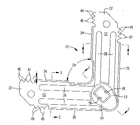
Fig. 1 is a plan view of an angled plate according to
the invention;
Fig. 2 is a cross-sectional view taken along lines 2-2
of Fig. l;
Fig. 3 is a cross-sectional view taken along lines 3-3
of Fig. l;
Fig. 4 is a cross-sectional view taken along lines 4-4
of Fig. l; and
Fig. 5 is a plan view of the angled plate shown in
Figs. 1-4 after being positioned within transverse flanges of a
duct section.

-
2166842
An angular plate 11 has a first leg 12 with an inner
end portion 33 joined to an inner end portion 14 of a second
leg 15. The first leg 12 is joined to the second leg 15 to form
an angle oC of 90. Stamped through connected portions of the
adjacent inner end portions 13, 14 is a rectangular opening 18.
As shown in Fig. 3, the first leg 12 has a substantially
planar top surface 21 and a substantially planar bottom surface 22.
Parallel inner and outer edges 24, 25 of the first leg are upwardly
turned to form strengthening flanges. The inner and outer edges
24, 25 extend longitudinally between the inner end portion 13 of
the first leg 12 and an outer end portion 27 thereof. Additional
strengthening of the first leg 12 is provided by a pair of
longitudinally extending parallel grooves 28 in the bottom surface
22.
The second leg portion 15 similarly has a planar top
surface 31 and a planar top bottom surface 32. Also parallel inner
and outer edges 34, 35 of the second leg 15 are upwardly turned to
form flanges. The inner and outer edges 34, 35 extend longitudinally
from the inner end portion 14 of the second leg 15 to an outer end
portion 37 thereof. Again, additional strengthening of the second
leg 15 is provided by a pair of longitudinally extending, parallel
grooves in the bottom surface 32.

- 21668~2
--6--
Formed on the outer end portion 27 of the first leg 12
are a plurality of teeth 41 having pointed outer ends 42 that
project transversely from the outer edge 25. Also formed on the
outer end portion 27 of the first leg 12 are a plurality of teeth
44 having pointed outer ends 45 that project transversely from the
inner edge 24. Similarly formed on the outer end portion 37 of
the second leg 15 are a plurality of teeth 46 having pointed outer
ends 47 that project transversely from the inner edge 34 and a
plurality of teeth 48 having pointed outer ends 49 that project
transversely from the outer edge 35. Preferably, the pointed
outer ends 42, 45, 47 and 49 project transversely from, respectively,
the outer edge 25 of the first leg 12, the inner edge 24 of the
first leg 12, the inner edge 34 of the second leg 15 and the outer
edge 35 of the second leg 15 by a distance d having a range between
.003 and .010 inches.
The angular plate 11 is used to join adjacent duct sections
in a manner similar to that described in the above noted U.S.Patents.
However, deficiencies of prior angular connecting plates are
eliminated by the projecting fingers 41, 44, 46 and 48 of the
angular plate 11. During assembly, the first and second legs 12,
14, respectively, are pressed into orthogonally related channels 51,
52 at the corner of a duct section 53 (Fig. 5). After full
insertion of the angular plate 11, the pointed outer ends 42 on the
outer end portion 27 of the first leg 12 penetrate an outer wall 55

21668~2
of the channel 51 and the pointed outer ends 45 penetrate an
inner wall 56 thereof. Similarly, the pointed outer ends 47 on
the outer end portion 37 of the second leg 15 penetrate an inner
wall 57 of the channel 52 while the pointed outer ends 49 penetrate
an outer wall 58, thereof.
The penetration of the channel walls 55, 56, 57 and 58,
respectively, by the pointed outer ends 42, 45, 47 and 49 securely
retains the angular plate 11 in position within the channels 51,
52. Subsequently, portions 61, 62, of the outer channel walls 55,
58 can be crimped over the outer edges 25, 35 of, respectively,
the first and second legs 12, 15 to further secure the annular
plate 11 in position. After similar positioning of an angular
plate 11 in each corner of the duct section 53, another duct
section (not shown) can be aligned therewith and secured thereto
by fastening bolts extending through the openings 18 in adjacent
pairs of the annular plates 11.
Obviously, many modifications and variations of the
present invention are possible in light of the above teachings.
It is to be understood, therefore, that the invention can be
practiced otherwise than as specifically described.

Representative Drawing
A single figure which represents the drawing illustrating the invention.
Administrative Status

2024-08-01:As part of the Next Generation Patents (NGP) transition, the Canadian Patents Database (CPD) now contains a more detailed Event History, which replicates the Event Log of our new back-office solution.

Please note that "Inactive:" events refers to events no longer in use in our new back-office solution.

For a clearer understanding of the status of the application/patent presented on this page, the site Disclaimer , as well as the definitions for Patent , Event History , Maintenance Fee  and Payment History  should be consulted.

Event History

Description Date
Inactive: IPC from MCD 2006-03-12
Time Limit for Reversal Expired 2000-01-10
Application Not Reinstated by Deadline 2000-01-10
Deemed Abandoned - Failure to Respond to Maintenance Fee Notice 1999-01-11
Application Published (Open to Public Inspection) 1996-07-18

Abandonment History

Abandonment Date Reason Reinstatement Date
1999-01-11

Maintenance Fee

The last payment was received on 1997-12-31

Note : If the full payment has not been received on or before the date indicated, a further fee may be required which may be one of the following

  • the reinstatement fee;
  • the late payment fee; or
  • additional fee to reverse deemed expiry.

Patent fees are adjusted on the 1st of January every year. The amounts above are the current amounts if received by December 31 of the current year.
Please refer to the CIPO Patent Fees web page to see all current fee amounts.

Fee History

Fee Type Anniversary Year Due Date Paid Date
MF (application, 2nd anniv.) - small 02 1998-01-20 1997-12-31
Owners on Record

Note: Records showing the ownership history in alphabetical order.

Current Owners on Record
CENTURY MANUFACTURING CO., INC.
Past Owners on Record
JOSEPH W. TIBERIO
Past Owners that do not appear in the "Owners on Record" listing will appear in other documentation within the application.
Documents

To view selected files, please enter reCAPTCHA code :


To view images, click a link in the Document Description column. To download the documents, select one or more checkboxes in the first column and then click the "Download Selected in PDF format (Zip Archive)" or the "Download Selected as Single PDF" button.

List of published and non-published patent-specific documents on the CPD .

If you have any difficulty accessing content, you can call the Client Service Centre at 1-866-997-1936 or send them an e-mail at CIPO Client Service Centre.


Document
Description 
Date
(yyyy-mm-dd) 
Number of pages   Size of Image (KB) 
Abstract 1996-05-06 1 26
Description 1996-05-06 6 191
Claims 1996-05-06 4 135
Drawings 1996-05-06 2 30
Representative drawing 1999-06-27 1 11
Reminder of maintenance fee due 1997-09-09 1 111
Courtesy - Abandonment Letter (Maintenance Fee) 1999-02-07 1 184
Fees 1997-12-30 1 47