Language selection

Search

Patent 2166959 Summary

Third-party information liability

Some of the information on this Web page has been provided by external sources. The Government of Canada is not responsible for the accuracy, reliability or currency of the information supplied by external sources. Users wishing to rely upon this information should consult directly with the source of the information. Content provided by external sources is not subject to official languages, privacy and accessibility requirements.

Claims and Abstract availability

Any discrepancies in the text and image of the Claims and Abstract are due to differing posting times. Text of the Claims and Abstract are posted:

  • At the time the application is open to public inspection;
  • At the time of issue of the patent (grant).
(12) Patent Application: (11) CA 2166959
(54) English Title: EPIDURAL CATHETER
(54) French Title: CATHETER PERIDURAL
Status: Deemed Abandoned and Beyond the Period of Reinstatement - Pending Response to Notice of Disregarded Communication
Bibliographic Data
(51) International Patent Classification (IPC):
  • A61M 25/04 (2006.01)
  • A61B 17/34 (2006.01)
  • A61M 25/00 (2006.01)
(72) Inventors :
  • CARRIE, LEN EDWARDS SCRYMGEOUR (United Kingdom)
(73) Owners :
  • LEN EDWARDS SCRYMGEOUR CARRIE
(71) Applicants :
(74) Agent: SMART & BIGGAR LP
(74) Associate agent:
(45) Issued:
(22) Filed Date: 1996-01-10
(41) Open to Public Inspection: 1996-07-26
Examination requested: 2002-10-29
Availability of licence: N/A
Dedicated to the Public: N/A
(25) Language of filing: English

Patent Cooperation Treaty (PCT): No

(30) Application Priority Data:
Application No. Country/Territory Date
9501424 (United Kingdom) 1995-01-25

Abstracts

English Abstract


Epidural catheter with a closed patient end and side openings are known. In the
present invention, the catheter forms a coil in its natural state, either in the plane of the length
of the catheter or helically, so that, when inserted in the epidural space, there is sufficient
length projecting into the space to ensure adequate retention but still ensuring that anaesthetic
fluid emerges close to the point of insertion.


Claims

Note: Claims are shown in the official language in which they were submitted.

THE EMBODIMENT OF THE INVENTION IN WHICH AN EXCLUSIVE PROPERTY
OR PRIVILEGE IS CLAIMED ARE DEFINED AS FOLLOWS:
1. An epidural catheter comprising a tube with a patient end and wherein said patient end
forms into a coil in its natural state.
2. A catheter according to Claim 1, wherein said coil lies in a plane including the length
of the catheter.
3. A catheter according to Claim 1, wherein said coil is formed by a region about 50mm
long at said patient end of the catheter.
4. A catheter according to Claim 1, wherein said catheter has a diameter of about 10 mm.
A catheter according to Claim 1, wherein said coil is helical.
6. A catheter according to Claim 1, wherein said patient end of the catheter is closed and
rounded, and wherein said catheter has at least one side opening close to said patient
end.
7. A catheter according to Claim 6, wherein said catheter has a plurality of openings close
to its patient end, and wherein said openings are spaced along a region about 4 mm
long.

8. A catheter according to any Claim 1, wherein said catheter has an external diameter of
about 1mm.
9. An epidural catheter comprising a tube with a patient end, wherein said patient end is
closed and rounded, wherein said patient end forms into a coil in a plane including the
length of the catheter in its natural state, and wherein the catheter has a plurality of
side openings at said patient end along said coil.
10. An epidural catheter comprising a tube with a patient end, wherein said patient end is
closed and rounded, wherein said patient end forms into a helical coil in its natural
state, and wherein the catheter has a plurality of side openings at said patient end along
said coil.
11. A method of performing epidural anaesthesia comprising the steps of: introducing a
hollow needle having a tip so that said tip is located in the epidural space, providing a
catheter of a kind having a patient end that forms into a coil in its natural state,
straightening said patient end and inserting it into the catheter until its patient end
emerges from the patient end of the needle and forms a coil within the epidural space,
removing said needle, and introducing anaesthetic fluid into the epidural space via the
catheter.

Description

Note: Descriptions are shown in the official language in which they were submitted.


~ 1 66~9
- 1 -
EPIDURAL CAlHLl~;K
Back~round of the Invention
This invention relates to epidural catheters.
Epidural catheters are used to introduce anaesthetic fluid into the epidural space. The
effectiveness of the anaesthesia block produced is dependent ~on the anaesthetic being
administered in the correct location. Conventional epidural catheters are straight and flexible.
They are usually closed at the tip and have several side openings through which fluid can
emerge from the catheter. It has been found that, if the tip of the catheter is inserted more than
about 10-20mm into the epidural space, the tip seldom remains in the desired location near the
site of insertion.but passes into the lateral or anterior parts of the epidural space. It is thought
that this may sometimes be the reason why epidural anaesthesia occasionally produces
imperfect blocks. Some anaesthetists prefer to leave a shorter length of catheter projecting into
the epidural space, to reduce the risk of the tip of the catheter moving away from the insertion
site. However, if insufficient length of catheter projects into the epidural space, movement
between the skin and ligamentum flavum can pull the catheter out of the epidural space and
result in injection of anaesthetic outside the epidural space.
Brief Summary of the Invention
It is an object of the present invention to provide an improved epidural catheter.
According to one aspect of the present invention there is provided an epidural catheter
having a patient end that forms into a coil in its natural state.
In this way, sufficient length of c~thet~ can be inserted into the epidural space to ensure
that it is not pulled out by movement between the skin and ligamentum flavum and yet the holes
through which the anaesthetic fluid emerges can be kept in the region of the insertion site.

216~9~9
- 2 -
The coil preferably lies in the plane of the catheter and is formed by a region about
50mm long at the patient end of the catheter, giving the coil a diameter of about 1 Omm.
Alternatively, the coil may be helical. The patient end of the catheter is preferably closed and
rounded, the catheter having at least one side opening close to its patient end. The catheter may
have a plurality of openings spaced along a region about 4mm long. The catheter preferably has
a diameter of about lmm.
It has previously been proposed in EP-A-497285 to coil the tip of a fine 30G spinal
catheter introduced into the subarachnoid space in order to ease insertion by re~ cing
obstruction by the anterior wall of the subarachnoid space. Also, this reduces the risk of the tip
of the catheter passing caudally and causing cauda equina syndrome. No one, however, has
previously addressed the problem of epidural catheters in the same way. Epidural catheters
differ from spinal catheters in that they are generally of larger diameter and are designed for
insertion into the epidural space, in which their direction of passage is determined by
surrounding tissues, especially fat and veins. By contrast, the sub-arachnoid space is filled with
cerebrospinal fluid and nerve roots which, with the anterior wall of the space are the only
significant factors influencing the direction taken by the spinal catheter. The considerations
involved in the design of spinal and epidural catheters are, therefore, quite di~elellL.
Two epidural catheters in accordance with the present invention, will now be described,
by way of example, with reference to the accompanying drawings.
`:
Brief Description of the Drawin~s
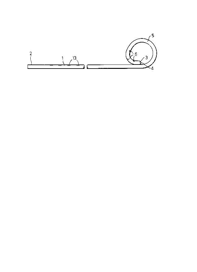
Figure 1 is a side elevation view of a first c~thet~r;
Figure 2 is an enlarged side elevation view of the patient
end of the catheter just prior to insertion;

- 2~66959
- 3 -
Figures 3A illustrate schematically three steps in the insertion
to 3C ofthe catheter;
Figure 4 is a perspective view of an alternative catheter; and
Figures 5A illustrate schematically three steps in the insertion of the alternative
to SC catheter.
Detailed Description of the Preferred Embodiments
With reference to Figure 1, the epidural catheter comprises a tube 1 of a flexible plastics
material, such as nylon. The tube is about 915mm long and is circular in section, with an
external diameter of lmm and an internal diameter of 0.58mm. Along the major part of its
length, the tube~is substantially straight. The machine end 2 of the catheter is square, plain and
open, enabling it to be joined to any conventional epidural connector.
The patient end 3 of the catheter has a smoothly rounded, closed tip 4 and, in its natural
state, forms a coil 5 in the plane of the straight part of the catheter. The coil 5 is about lOmm
in external diameter and is formed from a single turn ofthe catheter along a region about 50mm
long. The catheter has three openings 6 spaced from one another along a region 4mm long
extending from the patient end 3 of the coil 5. The openings 6 are distributed around the
circumference of the catheter.
In use, a conventional, hollow epidural needle 10 is inserted into the epidural space 11
in the usual way, as shown in Figure 3A. The needle 10 is preferably one that has a straight
shaft of Tuohy design so that the catheter emerges axially of the needle. When the needle 10 is
correctly located, a plastic sleeve 12 is slid along the catheter 1 from its machine end 2 until it
reaches the coiled region at the patient end 3. The coil 5 is straightened, as shown in Figure 2,
by sliding the sleeve 12 forwardly until the tip of the catheter is flush with the patient end of the
sleeve. The projecting patient end of the catheter 1 is now subst~nsi~lly straight, enabling it to

2166959
be inserted into the rear end of the needle 10. The diameter of the sleeve 12 is such that it
cannot enter the needle. The catheter 1 is pushed into the needle 10 by a measured distance, as
indicated by markings 13 on the catheter, so that the catheter emerges from the tip of the
needle by a distance of about 40-50mm. As the catheter emerges from the needle 10, it
resumes its natural, coiled state, as shown in Figure 3B. The needle 10 is then withdrawn,
leaving the catheter in position.
After removal of the needle 10, the anterior wall of the epidural space can relax,
fl~ttening the coil 5 against the ligamentum flavum 16. The machine end 2 of the catheter 1 is
connected to a conventional epidural catheter connector 14, in the usual way, as shown in
Figure 3C so that anaesthetic fluid can be supplied to the catheter, such as via a syringe. The
length of the catheter left projecting into the epidural space 11 is between 40-50mm, which is
sufficient to ensure that any movement between the skin 15 and the lig~m~n~lm flavum 16 will
not pull the catheter out of the epidural space 11. The length of catheter left projecting into the
epidural space is also chosen such that only the coiled part 5 of the catheter remains in the
epidural space The coiled configuration of the catheter ensures that anaesthetic fluid always
emerges into the epidural space 11 close to the insertion site, where it is most effective.
In the arrangement described above, the natural state of coil is in the same plane as the
major part of the length of the catheter. The coil could, however, be formed in a di~l ~llL plane,
as shown in Figures 4 and 5. In this arrangement, the natural shape of the coil 5' is shown in
Fig~ure 4 to be a tapering helix formed by the catheter taking a spiral path that increases
progressively in radius towards the patient end of the catheter, with the axis along the centre of
the helix being aligned with the rear part ofthe catheter. A~er removal of the needle 10', the
anterior wall of the epidural space bears on the patient end of the catheter and compresses it
against the ligamentum flavum 16 so that the coil 5' is flattened in a plane at right angles to the
major part of the length of the catheter, as shown in Figure 5C. This configuration may be more
likely to lie flat in the epidural space under the fl~ttçning action of the epidural tissues. The

~166959
previously-described configuration may be more likely to twist and hold the epidural space
open.

Representative Drawing
A single figure which represents the drawing illustrating the invention.
Administrative Status

2024-08-01:As part of the Next Generation Patents (NGP) transition, the Canadian Patents Database (CPD) now contains a more detailed Event History, which replicates the Event Log of our new back-office solution.

Please note that "Inactive:" events refers to events no longer in use in our new back-office solution.

For a clearer understanding of the status of the application/patent presented on this page, the site Disclaimer , as well as the definitions for Patent , Event History , Maintenance Fee  and Payment History  should be consulted.

Event History

Description Date
Inactive: IPC from MCD 2006-03-12
Application Not Reinstated by Deadline 2005-01-10
Time Limit for Reversal Expired 2005-01-10
Deemed Abandoned - Failure to Respond to Maintenance Fee Notice 2004-01-12
Amendment Received - Voluntary Amendment 2002-11-27
Letter Sent 2002-11-26
Inactive: Status info is complete as of Log entry date 2002-11-26
Inactive: Application prosecuted on TS as of Log entry date 2002-11-26
Request for Examination Requirements Determined Compliant 2002-10-29
All Requirements for Examination Determined Compliant 2002-10-29
Application Published (Open to Public Inspection) 1996-07-26

Abandonment History

Abandonment Date Reason Reinstatement Date
2004-01-12

Maintenance Fee

The last payment was received on 2002-12-20

Note : If the full payment has not been received on or before the date indicated, a further fee may be required which may be one of the following

  • the reinstatement fee;
  • the late payment fee; or
  • additional fee to reverse deemed expiry.

Please refer to the CIPO Patent Fees web page to see all current fee amounts.

Fee History

Fee Type Anniversary Year Due Date Paid Date
MF (application, 2nd anniv.) - standard 02 1998-01-20 1997-12-29
MF (application, 3rd anniv.) - standard 03 1999-01-11 1998-11-24
MF (application, 4th anniv.) - standard 04 2000-01-10 1999-11-25
MF (application, 5th anniv.) - standard 05 2001-01-10 2001-01-03
MF (application, 6th anniv.) - standard 06 2002-01-10 2001-12-20
Request for examination - standard 2002-10-29
MF (application, 7th anniv.) - standard 07 2003-01-10 2002-12-20
Owners on Record

Note: Records showing the ownership history in alphabetical order.

Current Owners on Record
LEN EDWARDS SCRYMGEOUR CARRIE
Past Owners on Record
None
Past Owners that do not appear in the "Owners on Record" listing will appear in other documentation within the application.
Documents

To view selected files, please enter reCAPTCHA code :


To view images, click a link in the Document Description column. To download the documents, select one or more checkboxes in the first column and then click the "Download Selected in PDF format (Zip Archive)" or the "Download Selected as Single PDF" button.

List of published and non-published patent-specific documents on the CPD .

If you have any difficulty accessing content, you can call the Client Service Centre at 1-866-997-1936 or send them an e-mail at CIPO Client Service Centre.


Document
Description 
Date
(yyyy-mm-dd) 
Number of pages   Size of Image (KB) 
Representative drawing 1998-01-29 1 3
Abstract 1996-01-10 1 11
Cover Page 1996-01-10 1 15
Description 1996-01-10 5 183
Drawings 1996-01-10 2 34
Claims 1996-01-10 2 54
Reminder of maintenance fee due 1997-09-11 1 111
Reminder - Request for Examination 2002-09-11 1 116
Acknowledgement of Request for Examination 2002-11-26 1 174
Courtesy - Abandonment Letter (Maintenance Fee) 2004-03-08 1 175
Fees 2002-12-20 1 39
Fees 2001-01-03 1 38
Fees 1999-11-25 1 38