Language selection

Search

Patent 2167121 Summary

Third-party information liability

Some of the information on this Web page has been provided by external sources. The Government of Canada is not responsible for the accuracy, reliability or currency of the information supplied by external sources. Users wishing to rely upon this information should consult directly with the source of the information. Content provided by external sources is not subject to official languages, privacy and accessibility requirements.

Claims and Abstract availability

Any discrepancies in the text and image of the Claims and Abstract are due to differing posting times. Text of the Claims and Abstract are posted:

  • At the time the application is open to public inspection;
  • At the time of issue of the patent (grant).
(12) Patent Application: (11) CA 2167121
(54) English Title: REDUCED SIZE APPARATUS FOR THE CENTRIFUGAL SEPARATION
(54) French Title: CENTRIFUGEUSE DE DIMENSIONS REDUITES
Status: Deemed Abandoned and Beyond the Period of Reinstatement - Pending Response to Notice of Disregarded Communication
Bibliographic Data
(51) International Patent Classification (IPC):
  • B01D 17/038 (2006.01)
  • B04B 01/02 (2006.01)
  • B04B 05/00 (2006.01)
(72) Inventors :
  • VADO, GIOVANNI ANTONIO (Italy)
  • MANCA, DOMENICO (Italy)
(73) Owners :
  • GIOVANNI ANTONIO VADO
  • DOMENICO MANCA
(71) Applicants :
(74) Agent: GOWLING WLG (CANADA) LLP
(74) Associate agent:
(45) Issued:
(22) Filed Date: 1996-01-12
(41) Open to Public Inspection: 1996-11-20
Examination requested: 2002-02-20
Availability of licence: N/A
Dedicated to the Public: N/A
(25) Language of filing: English

Patent Cooperation Treaty (PCT): No

(30) Application Priority Data:
Application No. Country/Territory Date
U.M. RM.95-U/000113 (Italy) 1995-05-19

Abstracts

English Abstract


The present invention relates to a reduced size apparatus (1)
for the centrifugal separation, comprising a housing (2), motor means (3)
coupled to said housing (2) and provided with a rotary shaft (6), cartridge
means (9; 13), provided within said housing (2) and coupled with said
rotary shaft (6), at least a first feeding channel (12) for the liquid to be
undergo to the centrifugal treatment from outdoor within said cartridge
means, at least a second channel (7) through said rotary shaft (6),
communicating with said cartridge means (9; 13), and at least a third
channel (8) for the ejection of the liquid, communicating with said second
channel (7).


Claims

Note: Claims are shown in the official language in which they were submitted.

CLAIMS
1. Apparatus for the centrifugal separation, characterized in
that it has reduced sizes and in that it comprises a housing, motor means
coupled to said housing and provided with a rotary shaft, cartridge means,
provided within said housing and coupled with said rotary shaft, at least a
first feeding channel for the liquid to be undergo to the centrifugal
treatment from outdoor within said cartridge means, at least a second
channel through said rotary shaft, communicating with said cartridge
means, and at least a third channel for the ejection of the liquid,
communicating with said second channel.
2. Apparatus according to claim 1, characterized in that said
cartridge means provide filtering means upstream with respect to said at
least a second channel.
3. Apparatus according to claim 1 or 2, characterized in that
said apparatus is provided with automatic operation means and/or failure
pilot light.
4. Apparatus according to one of the claims 1 - 3, characterized
in that said motor means are comprised of an electric motor.
5. Apparatus according to one of the claims 1 - 3, characterized
in that said motor means are comprised of a mechanical motor.
6. Apparatus according to one of the preceding claims,
characterized in that said motor means are provided with adjustment
means for the rotation speed.
7. Apparatus according to one of the preceding claims,
characterized in that said cartridge means are provided with an outlet
valve for the separated substances.
8. Apparatus according to one of the preceding claims,
characterized in that cartridge means can be of the disposable kind, being
removably coupled with said rotary shaft.
9. Apparatus according to one of the preceding claims,
characterized in that means for the fixing to the wall of the apparatus are
provided, for example a bracket and a plurality of screws.
10. Apparatus according to one of the preceding claims,
characterized in that more apparatuses serially or parallel connected are
provided.

11. Apparatus according to one of the preceding claims,
characterized in that it is provided with a sucking fan for the removal of
gases for the engine room, as provided by the existing rules.
12. Apparatus according to any one of the preceding claims,
substantially as illustrated and described.

Description

Note: Descriptions are shown in the official language in which they were submitted.


2167121
..
REDUCED SIZE APPARATUS FOR THE CENTRIFUGAL
SEPARATION
The present invention relates to a reduced size apparatus for
the centrifugal separation.
More particularly, the invention concerns an apparatus of-the
above kind suitable for the centrifugal separation and the filtering of the
combustible and incombustible fluids, or that can be employed in the food
field, for example for the filtering and the separation of alimentary oils,
realised in such a way to be manufactured with extremely reduced sizes in
view of the specific needing.
In the following, the specification will be referred particularly to
the use of that apparatus in the field concerning the separation and the
filtering of combustible liquids, and still more specifically in the nautical
field, the apparatus being able to pre-filter sea water before its
desalination, but it is evident that the apparatus according to the invention
can be used in many other fields, particularly in the food industry.
As it is well known, presently the centrifugal separators
provided on the boats in order to separate the gas oil from the water and
the other impurities before the gas oil is sent to the engine have
remarkable sizes and are very expensive.
On the other hand, it s also known that their use is unavoidable
in order to avoid damaging of the engine injection system and mainly to
- avoid to have a breakdown in the sea for problems due to the entrance of
water or impure substances in the powering apparatuses or to the
clogging of the filters.
However, it is well evident that the known centrifugal
separalors have noticeable problems to be provided particularly in very
little boats.
A first problem is that deriving from the costs, objectively not
proportioned with respect to the value of the boat.
Another problem, surely more important, is the one concerning
the overall dimensions: in fact it is well known to everybody that the
engine housing in any boat, and particularly in those having medium -
little sizes, is rather narrow, so that it is difficult, and many cases
impossible, to mount the separator.
Furthermore, none of the solutions presently available on the
market is sufficiently reliable, so as to guarantee a safe navigation.

216~121
Finally, another specific problem of the known separators is
due to the need of being operated by the user.
In this contest, the Applicants have realised an apparatus of
the above kind that can be miniaturised in function of the needing, thus
being suitable for any kind of available space.
Another object of the present invention is that of realising an
apparatus really cheap.
A still further object of the present invention is that of providing
an extremely reliable apparatus which does not require the intervention of
the operator for its operation.
Another object of the present invention is that of providing an
apparatus working without the exposure of the products at the
environment.
Still another object of the present invention is that of providing
an apparatus that can be used in different technical fields, among which
the food field for the treatment of some products, for example for
guaranteeing a higher purity in the mineral water, wine, oil bottling plants
without the exposure of the products at the environment, thus preventing
the oxidation phenomenon.
It is therefore specific object of the present invention a reduced
size apparatus for the centrifugal separation, comprising a housing, motor
means coupled to said housing and provided with a rotary shaft, cartridge
means, provided within said housing and coupled with said rotary shaft, at
- least a first feeding channel for the liquid to be undergo to the centrifugal
treatment from outdoor within said cartridge means, at least a second
channel through said rotary shaft, communicating with said cartridge
means, and at least a third channel for the ejection of the liquid,
communicating with said second channel.
Preferably, according to the invention, said cartridge means
provide filtering means upstream with respect to said at least a second
channel.
Further, according to the invention, said apparatus can be
provided with automatic operation means and/or failure pilot light.
Said motor means, which can be electrical or mechanical, can
be, according to the invention, provided with adjustment means for the
rotation speed.
:

2167121
According to the invention, said cartridge means can be
provided with an outlet valve for the separated substances.
Still according to the invention, said cartridge means can be of
the disposable kind, being removably coupled with said rotary shaft.
Further, means for the fixing to the wall of the apparatus
according to the invention could be provided, for example a bracket and a
plurality of screws.
Always according to the invention, more apparatuses serially or
parallel connected can be provided.
Finally, it can be provided with a sucking fan for the removal of
gases for the engine room, as provided by the existing rules.
The present invention will be now described for illustrative, but
limitative purposes according to its preferred embodiments, with particular
reference to the figures of the enclosed drawings, wherein:
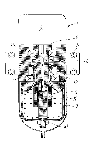
figure 1 is a section view of a first embodiment of the apparatus
according to the invention; and
Figure 2 is a section view of a second embodiment of the
apparatus according to the invention.
Observing now at first figure 1, the apparatus 1 according to
the invention comprises an housing 2 and a motor 3 coupled above said
housing.
Said housing is provided with a bracket 4 for the fixing of the
apparatus 1 at a wall by the bolts 5 or similar fixing means.
Said motor 3 is provided with a rotary shaft 6, within which
liquid passage-and ejection channels 7,8 are realised.
In the lower portion of the housing 2, a cartridge fixedly rotating
with said shaft 6 is provided.
The cartridge 9 is provided below with an outlet valve 10, and
integral with said shaft, at the entrance of said channels 7, with a filter.
Furthermore, channels 12 for the entrance of the liquid to be
centrifuged are realised on the housing.
The liquid, let suppose gas oil, along with its impurities and
water, but the same applies also to other liquids, for example in the food
field, enters through the channels 12 and goes within the cartridge 9,
which is rotating with the shaft 6 of the motor 3.

2167121
-
Here, the centrifugation of the heavier liquid, water, remains
within the cartridge, while the lighter one, gas oil, passes through the
channels 7 and 8 to be sent to the boat engine.
The filter 11 will eliminate the solid impurities.
When the cartridge 9 will be full, opening the valve 10, the
water is discharged so that the apparatus is again able to operate.
The solution shown in figure 2 is very similar to the solution of
figure 1, so that the corresponding parts will be indicated by the same
numerical references.
In this case the cartridge 13 is disposable, so that once it is full,
it is sufficient to disassemble the cartridge and to replace the same by a
new one.
In the specific marine use, for example a pair of apparatuses 1
working in parallel according to the invention can be provided, so that it is
possible to work with the maximum safe without the risk of have a
breakdown with not repairable failures. for example mood moved by the
troubled sea.
As already mentioned, the apparatus according to the invention
can provide an electric or mechanical motor, having an adjustable speed,
provided with an automatic operation and failure pilot light.
The present invention has been described for illustrative, but
not limitative purposes according to its preferred embodiments, but it is to
be understood that modifications and/or changes can be introduced by
those skilled in the art without departing from the relevant scope as defined in the enclosed claims.

Representative Drawing
A single figure which represents the drawing illustrating the invention.
Administrative Status

2024-08-01:As part of the Next Generation Patents (NGP) transition, the Canadian Patents Database (CPD) now contains a more detailed Event History, which replicates the Event Log of our new back-office solution.

Please note that "Inactive:" events refers to events no longer in use in our new back-office solution.

For a clearer understanding of the status of the application/patent presented on this page, the site Disclaimer , as well as the definitions for Patent , Event History , Maintenance Fee  and Payment History  should be consulted.

Event History

Description Date
Inactive: IPC from MCD 2006-03-12
Application Not Reinstated by Deadline 2004-01-12
Time Limit for Reversal Expired 2004-01-12
Deemed Abandoned - Failure to Respond to Maintenance Fee Notice 2003-01-13
Amendment Received - Voluntary Amendment 2002-07-04
Letter Sent 2002-03-01
Inactive: Status info is complete as of Log entry date 2002-03-01
Inactive: Application prosecuted on TS as of Log entry date 2002-03-01
Request for Examination Requirements Determined Compliant 2002-02-20
All Requirements for Examination Determined Compliant 2002-02-20
Application Published (Open to Public Inspection) 1996-11-20

Abandonment History

Abandonment Date Reason Reinstatement Date
2003-01-13

Maintenance Fee

The last payment was received on 2001-12-20

Note : If the full payment has not been received on or before the date indicated, a further fee may be required which may be one of the following

  • the reinstatement fee;
  • the late payment fee; or
  • additional fee to reverse deemed expiry.

Patent fees are adjusted on the 1st of January every year. The amounts above are the current amounts if received by December 31 of the current year.
Please refer to the CIPO Patent Fees web page to see all current fee amounts.

Fee History

Fee Type Anniversary Year Due Date Paid Date
MF (application, 2nd anniv.) - small 02 1998-01-20 1997-11-19
MF (application, 3rd anniv.) - small 03 1999-01-12 1998-12-22
MF (application, 4th anniv.) - small 04 2000-01-12 1999-12-13
MF (application, 5th anniv.) - small 05 2001-01-12 2000-12-14
MF (application, 6th anniv.) - small 06 2002-01-14 2001-12-20
Request for examination - small 2002-02-20
Owners on Record

Note: Records showing the ownership history in alphabetical order.

Current Owners on Record
GIOVANNI ANTONIO VADO
DOMENICO MANCA
Past Owners on Record
None
Past Owners that do not appear in the "Owners on Record" listing will appear in other documentation within the application.
Documents

To view selected files, please enter reCAPTCHA code :


To view images, click a link in the Document Description column (Temporarily unavailable). To download the documents, select one or more checkboxes in the first column and then click the "Download Selected in PDF format (Zip Archive)" or the "Download Selected as Single PDF" button.

List of published and non-published patent-specific documents on the CPD .

If you have any difficulty accessing content, you can call the Client Service Centre at 1-866-997-1936 or send them an e-mail at CIPO Client Service Centre.

({010=All Documents, 020=As Filed, 030=As Open to Public Inspection, 040=At Issuance, 050=Examination, 060=Incoming Correspondence, 070=Miscellaneous, 080=Outgoing Correspondence, 090=Payment})


Document
Description 
Date
(yyyy-mm-dd) 
Number of pages   Size of Image (KB) 
Representative drawing 1998-03-18 1 35
Abstract 1996-01-11 1 20
Description 1996-01-11 4 197
Claims 1996-01-11 2 60
Drawings 1996-01-11 1 60
Reminder of maintenance fee due 1997-09-13 1 111
Acknowledgement of Request for Examination 2002-02-28 1 180
Courtesy - Abandonment Letter (Maintenance Fee) 2003-02-09 1 176
Fees 1999-12-12 1 30
Fees 1997-11-18 1 33
Fees 2000-12-13 1 29
Fees 1998-12-21 1 33
Fees 2001-12-19 1 28