Language selection

Search

Patent 2167212 Summary

Third-party information liability

Some of the information on this Web page has been provided by external sources. The Government of Canada is not responsible for the accuracy, reliability or currency of the information supplied by external sources. Users wishing to rely upon this information should consult directly with the source of the information. Content provided by external sources is not subject to official languages, privacy and accessibility requirements.

Claims and Abstract availability

Any discrepancies in the text and image of the Claims and Abstract are due to differing posting times. Text of the Claims and Abstract are posted:

  • At the time the application is open to public inspection;
  • At the time of issue of the patent (grant).
(12) Patent: (11) CA 2167212
(54) English Title: A METHOD OF JOINING REINFORCED THERMOPLASTIC PIPES
(54) French Title: METHODE D'ASSEMBLAGE DE TUYAUX DE THERMOPLASTIQUE RENFORCE
Status: Deemed expired
Bibliographic Data
(51) International Patent Classification (IPC):
  • B29C 65/00 (2006.01)
  • B29C 65/20 (2006.01)
  • B29C 65/34 (2006.01)
  • F16L 47/03 (2006.01)
(72) Inventors :
  • GREIG, JOHN MARTYN (United Kingdom)
(73) Owners :
  • BG PLC (United Kingdom)
(71) Applicants :
(74) Agent: GOWLING WLG (CANADA) LLP
(74) Associate agent:
(45) Issued: 1999-01-19
(86) PCT Filing Date: 1994-07-19
(87) Open to Public Inspection: 1995-02-02
Examination requested: 1996-01-12
Availability of licence: N/A
(25) Language of filing: English

Patent Cooperation Treaty (PCT): Yes
(86) PCT Filing Number: PCT/GB1994/001566
(87) International Publication Number: WO1995/003162
(85) National Entry: 1996-01-12

(30) Application Priority Data:
Application No. Country/Territory Date
9314971.4 United Kingdom 1993-07-20

Abstracts

English Abstract


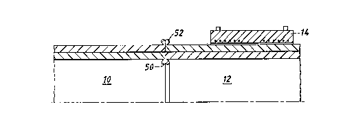
An electrofusion coupler (14) is slid over one
of two thermoplastic pipes (10, 12) each having a
layer or layers of reinforced fibres (34) between
the centre of the wall of thc pipe and the outside
surface (38). The end surfaces are trimmed in a
butt fusion machine and the resulting end surfaces
(40, 42) are forced against a heater plate. The
plate is removed and the end surfaces are forced
together. Internal and external beads (50, 52)
involving inward and outward flow of material
result, the outward flow ensures that there is at the
welded joint an inner layer (60) which is free from
reinforcement fibres. The external bead (52) is
removed and the coupler is slid over the butt fused
welded joint and energised to cause it to become
fusion welded to the outside of the pipe.


French Abstract

Un dispositif d'accouplement par électrofusion (14) coulisse sur un des deux tuyaux thermoplastiques (10, 12), chacun ayant une couche ou des couches de fibres renforcées (34) situées entre le centre de la paroi du tuyau et la surface externe (38). Les surfaces terminales sont dressées dans une machine de fusion bout-à-bout et les surfaces terminales résultantes (40, 42) sont poussées contre une plaque chauffante. La plaque est retirée et les surfaces terminales sont poussées l'une contre l'autre. L'écoulement interne et externe de la matière entraîne la formation de cordons interne et externe (50, 52). L'écoulement externe assure la formation, au niveau du joint soudé, d'une couche interne (60) qui est dépourvue de fibres de renforcement. On retire le cordon externe (52) et on fait coulisser le dispositif d'accouplement sur le joint soudé par fusion bout-à-bout, et ce dispositif d'accouplement reçoit un courant d'excitation afin que ce cordon externe soit soudé par fusion à la surface externe du tuyau.

Claims

Note: Claims are shown in the official language in which they were submitted.


-9-
CLAIMS


1. A method of joining two reinforced thermoplastic pipes by a butt fused
welded joint, each pipe having an inside and an outside surface and
a pipe wall extending between the inside and the outside surface and
one or more layers of reinforcement fibres, lying within the outer
half of the pipe wall, the end portions of the pipes being heated by
being forced against a heater plate interposed between them so that
thermoplastic material from the end portions of the pipes becomes
molten and then following removal of the heater plate the end surfaces
are forced together and molten material from the end portions is upset
involving inward and outward flow of thermoplastic material to form
internal and external beads, after which the pipes are allowed to
cool, and the or each reinforcement layer is wholly or primarily
displaced outwardly by said outward flow during upsetting from its
original position so that, at the welded joint, there is a layer of
thermoplastic material between the layer or layers of reinforcement
fibres and the common inside surface which is free from reinforcement
fibres.

2. A method according to Claim 1 in which after the butt fused welded
joint has been formed on electrofusion coupler is positioned over the
joint and is energised for a sufficient time to cause the coupler to
become joined to the two pipes by electrofusion welded joints.

3. A method according to Claim 2 the external bead being removed before
the coupler is positioned over the butt fused welded joint.

- 10 -
4. A method according to Claim 2, the coupler having a radial clearance
between the coupler and the outside surface of the pipes and the
external bead being small enough to be accommodated within the radial
clearance.

5. A method according to any one of Claims 2 to 4 in which said
electrofusion coupler is an intermediate one of three electrofusion
couplers joined together end-to-end, the outermost couplers being
joined respectively by electrofusion welded joints to said pipes.

6. A method according to Claim 5 in which said electrofusion couplers are
joined together by butt welded joints.

7. A method according to Claim S or Claim 6 in which said intermediate
electrofusion coupler is joined first of all by electrofusion joints
to said pipes after which said outermost couplers are joined by
electrofusion welded joints to said pipes.

8. Pipes when joined by the method claimed in any preceding claim.

9. A method according to Claim 1 substantially as hereinbefore described
with reference to Figures 1 to 5 of the accompanying drawings.

10. A method according to Claim 1 substantially as hereinbefore described
with reference to Figure 6 of the accompanying drawings.

11. Pipes when joined by the method claimed in Claim 9 or by the method
claimed in Claim 10.

Description

Note: Descriptions are shown in the official language in which they were submitted.


W O 95/03162 ~ 1 ~ 7 ~ 1 2 PCT/GB94/01566


~ heTHOD 0~ JOrNrNG RErNFORCED
l~lF:RH~PLI~STIC PIPES


The invention relates to methods of joining reinforced thermoplastic pipes.

Thè invention partic~ rly~ though not exclusively, relates to joining of
pipes which have their pressure rating Pnh~n~ed by each having a layer or
layers of ibre reinforc t. The fibres, for e .1P, can be wound
directly over an inner pipe of thr ~plastic material or can be preformed
into tapes before winding. In another example, the fibres or tapes extend
purely longin-din~lly doYn the inner pipe. An external layer of
thermoplas~ic material, not npcess~rily of the same type or grade as the
inner pipe, is added over the reinforcement to completely cover the latter
for protection. The fibres or tapes may be fused to each other and to the
inner pipe and the external layer or, if preferred, the fibres or tapes may
be loose. The inner pipe together, ~ith the b~Lo~-ding layer or layers of
reinforcement and with the added external layer, forms a pipe having a pipe
wall between the inside surface of the inner pipe and the outside surface
of the external layer and the layer or each of the layers of reinforcement
lies at the centre of the pipe wall or lies between the centre and the
outside surface of the external layer.

It is kno~n to join thermoplastic reinforced pipes using a ~~h~nic~l
fitting ~hich is clamped onto the pipe, for example, or ~hich compresses
the thermoplastic material between an inner metal supporting tube and
external metal collar. Such fittings are designed to create a fluid seal

W O 95/03162 2 1 6 7 2 1 2 PCTIGB94/01566 - 2 -

and to have substantial resistance to "pull out" of the pipe from the
fitting.

Such fittings, which are largely of metal, are subject to corrosion.
Moreover, the internal fluid may affect the properties of the thermoplastic
so that it softens, with the result that the clamping forces, and hence the
seal and "pull out" characteristics, are lost over a period of time.

It is the aim of the invention to avoid the use of such fittings.

According to the invention, a method of joining two reinforced
thermoplastic pipes by a butt fused welded joint is provided, each pipe
having an inside and an outside surface and a pipe wall ext~n~;ng between
the inside and the outside surface and one or more layers of reinforcement
fibres lying within the outer half of the pipe wall, the end portions of
the pipes being heated by being forced against a heater plate interposed
between them so that thermoplastic material from the end portions of the
pipes becomes molten and then following removal of the heater plate the end
surfaces are forced together and molten material from the end portions is
upset involving inward and outward flow of thermoplastic material to form
internal and external beads, after which the pipes are allowed to cool
while being constrained against axial separating ~v~ -t, and the or each
reinforcement layer is wholly or primarily displaced outwardly by said
outward flow during upsetting from its original position so that, at the
welded joint, there is a layer of thermoplastic material between the layer
or layers of reinforcement fibres and the common inside surface which layer
is free from reinforcement fibres.

W 0 95/03162 ~ 2 1 6 7 2 1 2 PCT/GB94/01566 - 3 -


Embodimen~s of the invention will now be described by way of example with
reference to the accompanying drawings, in which:-


Figures 1 to 4 show various stages of joining two thermoplastic pipestogetller;


Figure 5 shows on a larger scale the zone of the joint shown circled in
Figure 2; and


Figure 6 shows a second embodiment.


Figure 1 shows two pipes 10, 12 which are to be joined by a butt fused
welded joint. One pipe 12 has an electrofusion coupler 14 encircling the
pipe 12. The coupler 14 is a loose fit upon the pipe 12, a diametral
clear_nce 16 being shown. The coupler 14 carries a heating el ~ t which
is embedded in the thermoplastic wall of the coupler and comprising two
groups 18, 20 of wind;ngs surrounding the pipe 12. The heAt;ng coil is
connected to te. nAls (not shown) within shr.~lds 22, 24 integral with the
coupler 14.


Each pipe 10, 12 comprises an inner pipe 30 of thermoplastic material
having an inside surface 32; a layer or layers of reinforcement fibres
34 wound around the inner pipe 30 or extend;ng merely longitu~in~lly down
the pipe 30; and an external layer of thermoplastic material 36, which has
been added to the inner pipe 30 following application of the layer or
layers 34~ The external layer 36 has an outside surface 38.


W O 95/03162 2 1 ~ 7 2 1 2 PCT/GB94/01566 - 4 -

Each pipe 10, 12 thus has a pipe wall between the inside surface 32 and the
outside surface 38.

Before joining the end surfaces of the pipes 10, 12 they are accuratelytrimmed so that clean surfaces 40, 42 of the pipes are produced. This
operation is performed while the pipes 10, 12 are held in a butt fusion
ach;ne (not shown). The pipes 10, 12 are then forced by hydraulic
cylinders against a heater plate (not shown) which is interposed between
the pipe ends 40, 42. Initial beads are formed on each pipe as the
thermoplastic material becomes molten and is upset by the applied axial
load.

The pipes 10, 12 are held against the heater plate for a heat soak period.
Next, the pipes 10, 12 are retracted from the plate, the plate is removed
and the pipes 10, 12 are brought together under an axial load. Holten
material from the end portions of the pipes 10, 12 is upset, involving
inward and outward flow of thermoplastic material to form final internal
and external beads 50, 52.

The pipes 10, 12 are allowed to cool, the axial force being removed during
the final stage of cooling although the pipes 10, 12 are constrained
against axial separating ~ L ( Figure 2).

The or each reinforcement layer 34 of each pipe 10, 12 is wholly or
primarily displaced outwardly at 58 by the outward flow of thermoplastic
material from its original position (Figure 5). The result is that, at the
welded joint, there is a layer 60 of thermoplastic material adjoining the

~; f 2 1 6 7 2 1 2
W O 95/03162 PCT/GB94/01566

common inside surface 32 which is free from reinforcement fibres.

Next, the external bead 52 is removed (Figure 3) and the electrofusion
coupler 14 is centralised over the butt fused welded joint by sliding it
along the pipe 12 until it half covers the pipe 10 and half covers the
pipe 12.

Finally, the te n~l$ are connected to a source of electrical energy and
current is passed through the he~ting element for a sufficient time for the
coupler 14 to become welded by electrofusion to the end portions of the
pipes 10, 12 (Figure 4). A small central zone, between the group 18 of
w;n~ings and the group 20 of win~ings~ is not fused and contains the stub
of the external bead 52.

By way of example, joints have been made between pipes of polyethylene
reinforced with aramid fibres. The pipes were 125 millimetres in outside
diameter and had a wall thickness of 11.5 'lli ~t-es. The quotient found
by dividing the outside diameter by the wall thicknPss, which is known as
the Standard Dimension Ratio (SDR), was 11. The internal and external
beads were 11 illi -tres wide (ie measured parallel to the length of the
pipe) and S millimetres high (ie measured radially with respect to the
pipe). In other examples, the internal and external beads were very small,
being 3 I lli tres wide and 2 ri 11 i ~t.es high.

In these examples, the inner pipe 30 and the external layer 36 were of the
same grade of polyethylene. However, in general, the inner pipe 30 and the
external layer 36 can be composed of the same or different grades of the

W 0 95/03162 - 6 - PCT/GB94/01566

same thermoplastic material or be composed of the same or different
thermoplastic materials.

The larger beads are preferred where it is necessary to perform qualitycontrol checks on the performance and consistency of the butt weld, the
bead being readily removed for inspection. On the other hand, very small
beads are advantageous because the internal bead does not impede the flow
of product as much as the larger bead. Also, it would not be necessary to
remove the external bead in order to allow the electrofusion coupler to
slide over the butt fused joint, the clearance between the coupler and the
pipe being large enough to ~cc~ ~d~te the external bead. In practice any
size of bead could be produced depending on the engineering requirements.
Also, the invention is appl;c~hle to a wide range of pipe sizes and SDR's,
the examples quoted are given purely as examples.

In the completed joint, the flow of molten pipe material during the making
of the butt fused welded joint ensures that there is a layer 60, which is
free from reinforcement fibres, which is at approximately the same
thickness as the thickness of the original inner tube 30. Consequently
aggressive chemicals or fluids flowing in the pipe, which may be under a
pressure of, for example, 25 bar are kept away from the highly stressed
fibre reinfo1c t. However, as there are fibres in the outer part of the
butt joint, the weld interface will be weakened, resulting in the risk of
brittle fracture from axial or bending loads on the pipe.

Nevertheless, the butt joint effected by the invention is very useful where
such loads are kept within limits.

W O 95/03162 2 1 ~ 7 2 1 2 PCT/GB94/01566 - 7 -


However, in the preferred form of joint, an electrofusion coupler 14 is
fusion welded over the butt welded joint, which strengthens the joint
substantially. The coupler 14 stops the butt joint from breaking in
service and also protects the fibres protruding to or close to the external
surface of the debeaded butt joint from the external environment. If
access to the fibres was permitted, pressurised gases and liquids would
pe- 7~te considerable distances along the fibres by capillary action. High
pressure gas within the fibres could lead to disbon~;ng along the
reinforced layer. This could result in bursting the outer layer off the
pipe or, in the event of pipeline depressuris~t;on, collapse of the inner
pipe 30.


In the examples quoted above, tests proved that the pipe burst at 125 bar
without visible damage to the joint. Normally, a non-reinforced
polyethylene pipe with either a butt joint and/or an electrofusion joint
would burst the pipe at about 30 bar.


Figure 6 shows a further embodiment. In this embodiment, three
electrofusion couplers 70, 72, 74 are joined together end-to-end by
butt-welds. The assembly of three couplers is then slid over one of the
two pipes 76, 78 which are to be joined. The two pipes 76, 78 are
butt-welded as before, the joint being shown at 80 and the external bead is
removed, leaving the internal bead shown at 82.


The assembly of three couplers was then slid over the joint 80, with the
middle coupler 72 str~d~li ng the joint 80.


W O 95/03162 .- ~ _ 2 1 6 7 2 1 2 PCT/GB94/01566 - 8 -

The coupler 72 was joined to each pipe 76, 78 by an electrofusion welded
joint, as before. Then, each of the two outer couplers 70, 74 was joined
to the respective pipe 76 or 78 by electrofusion welded joints, as shown in
Figure 6.

Higher burst pressures are sustained by the Figure 6 embodiment than the
embodiment of Figures 1 to 5.

Representative Drawing
A single figure which represents the drawing illustrating the invention.
Administrative Status

For a clearer understanding of the status of the application/patent presented on this page, the site Disclaimer , as well as the definitions for Patent , Administrative Status , Maintenance Fee  and Payment History  should be consulted.

Administrative Status

Title Date
Forecasted Issue Date 1999-01-19
(86) PCT Filing Date 1994-07-19
(87) PCT Publication Date 1995-02-02
(85) National Entry 1996-01-12
Examination Requested 1996-01-12
(45) Issued 1999-01-19
Deemed Expired 2004-07-19

Abandonment History

There is no abandonment history.

Payment History

Fee Type Anniversary Year Due Date Amount Paid Paid Date
Application Fee $0.00 1996-01-12
Registration of a document - section 124 $0.00 1996-04-04
Maintenance Fee - Application - New Act 2 1996-07-19 $100.00 1996-07-05
Maintenance Fee - Application - New Act 3 1997-07-21 $100.00 1997-07-04
Maintenance Fee - Application - New Act 4 1998-07-20 $100.00 1998-07-03
Registration of a document - section 124 $50.00 1998-09-08
Final Fee $300.00 1998-09-08
Maintenance Fee - Patent - New Act 5 1999-07-19 $150.00 1999-06-14
Maintenance Fee - Patent - New Act 6 2000-07-19 $150.00 2000-06-14
Maintenance Fee - Patent - New Act 7 2001-07-19 $150.00 2001-06-13
Maintenance Fee - Patent - New Act 8 2002-07-19 $150.00 2002-06-12
Owners on Record

Note: Records showing the ownership history in alphabetical order.

Current Owners on Record
BG PLC
Past Owners on Record
BRITISH GAS PLC
GREIG, JOHN MARTYN
Past Owners that do not appear in the "Owners on Record" listing will appear in other documentation within the application.
Documents

To view selected files, please enter reCAPTCHA code :


To view images, click a link in the Document Description column. To download the documents, select one or more checkboxes in the first column and then click the "Download Selected in PDF format (Zip Archive)" or the "Download Selected as Single PDF" button.

List of published and non-published patent-specific documents on the CPD .

If you have any difficulty accessing content, you can call the Client Service Centre at 1-866-997-1936 or send them an e-mail at CIPO Client Service Centre.


Document
Description 
Date
(yyyy-mm-dd) 
Number of pages   Size of Image (KB) 
Representative Drawing 1997-06-12 1 7
Description 1995-02-02 8 248
Cover Page 1996-05-13 1 16
Drawings 1995-02-02 3 55
Claims 1995-02-02 2 65
Abstract 1995-02-02 1 48
Cover Page 1999-01-15 1 52
Representative Drawing 1999-01-15 1 5
Fees 1997-07-04 1 32
Fees 1998-07-03 1 31
Assignment 1998-09-08 1 40
Correspondence 1998-09-08 1 40
Correspondence 1998-11-04 1 1
National Entry Request 1996-02-09 2 57
National Entry Request 1996-01-12 4 132
Correspondence Related to Formalities 1996-03-27 1 20
International Preliminary Examination Report 1996-01-12 9 632
Prosecution Correspondence 1996-01-12 3 139
Office Letter 1996-02-16 1 27
Fees 1996-07-05 1 31