Language selection

Search

Patent 2167253 Summary

Third-party information liability

Some of the information on this Web page has been provided by external sources. The Government of Canada is not responsible for the accuracy, reliability or currency of the information supplied by external sources. Users wishing to rely upon this information should consult directly with the source of the information. Content provided by external sources is not subject to official languages, privacy and accessibility requirements.

Claims and Abstract availability

Any discrepancies in the text and image of the Claims and Abstract are due to differing posting times. Text of the Claims and Abstract are posted:

  • At the time the application is open to public inspection;
  • At the time of issue of the patent (grant).
(12) Patent Application: (11) CA 2167253
(54) English Title: BUCKLE FOR SAFETY BELTS
(54) French Title: BOUCLE POUR CEINTURE DE SECURITE
Status: Deemed Abandoned and Beyond the Period of Reinstatement - Pending Response to Notice of Disregarded Communication
Bibliographic Data
(51) International Patent Classification (IPC):
  • A44B 11/00 (2006.01)
  • A44B 11/25 (2006.01)
  • A62B 35/00 (2006.01)
(72) Inventors :
  • WIER, FRANZ (Germany)
(73) Owners :
  • TRW OCCUPANT RESTRAINT SYSTEMS GMBH
(71) Applicants :
(74) Agent: SMART & BIGGAR LP
(74) Associate agent:
(45) Issued:
(22) Filed Date: 1996-01-15
(41) Open to Public Inspection: 1996-07-27
Examination requested: 1996-02-29
Availability of licence: N/A
Dedicated to the Public: N/A
(25) Language of filing: English

Patent Cooperation Treaty (PCT): No

(30) Application Priority Data:
Application No. Country/Territory Date
195 02 416.8 (Germany) 1995-01-26

Abstracts

English Abstract


The pretensioner-proof buckle for safety belts has a latch
(12) which is movably mounted in a load-bearing frame (10)
between an opened position and a closed position and which
in its closed position acts on an insert tongue. A release
button (14) has a sliding mounting on the frame (10) of this
buckle, the pressing of which allows the latch (12) to be
pushed into its open position. A compensating mass forms one
arm of a lever (16) pivotally mounted on the frame. The
release button (14) has two limit stops (14a, 14b) which are
spaced from each other in the direction of their sliding
movement. The lever (16) has a first lever arm (16c), the
free end of which is located opposite the first limit stop
(14a) of the release button, and a second lever arm (16d),
the free end of which is located opposite the second limit
stop (14b) of the release button.


Claims

Note: Claims are shown in the official language in which they were submitted.

- 5 -
Claims
1. Buckle for safety belts, with a latch (12) which is
movably mounted in a load-bearing frame (10) between an
opened position and a closed position and which in its
closed position acts on an insert tongue, a release button
(14) with a sliding mounting on the frame, the actuation of
which allows the latch to be pushed into its open position,
and a compensating mass, which forms one arm of a lever (16)
pivotally mounted on the frame of the buckle, said buckle
being characterized by the release button (14) having two
limit stops (14a, 14b) which are spaced from each other in
the direction of their sliding movement, and by the lever
(16) having a first lever arm (16c), the free end of which
is located opposite the first limit stop (14a) of the
release button, and a second lever arm (16d), the free end
of which is located opposite the second limit stop (14b) of:
the release button.
2. Buckle in accordance with Claim 1, characterized by the
compensating mass being distributed over two parallel arms
(16a, 16b) connected to each other through the pivot axis of
the lever.
3. Buckle in accordance with any one of the above Claims,
characterized by the lever being biased into the initial
position by a spring (20).

Description

Note: Descriptions are shown in the official language in which they were submitted.


7~
Buckle for Safety Belts
The invention relates to a buckle for safety belts suitable
for a belt system with a seat-belt pretensioner acting on
the buckle.
Such a buckle, a so-called pretensioner-proof buckle, is
already known from DE 39 29 114 A1; this is fitted with a
c~ cating mass in order to r ,~ -ate for the forces of
inertia occurring during extreme acceleration or decelera-
tion and thus to prevent unintentional opening of the
buckle. The ~- -n~P~ting mass forms one arm of a lever
pivotally mounted on the frame of the buckle. With a further
arm, the lever acts on the release button of the buckle, and
this button has a sliding mounting on the frame of this
buckle .
The invention is based on the need to provide the buckle
with high safety reserves, in order to reliably prevent the
buckle from opening even under conditions of extreme accel-
eration or deceleration, and taking tolerances and ageing
into account.
In accordance with the invention, a buckle for safety belts
is to be created with a latch which is movably mounted in a
load-bearing frame between an opened position and a closed
position and which in its closed position acts on an insert
tongue, a release button with a sliding mounting on the
frame of this buckle, the pressing of which allows the latch
to be pushed into its open position, and a, -nc~ting
mass, which forms one arm of a lever pivotally mounted on
the frame of the buckle, whereby said buckle is character-
ized by the release button having two limit stops which are
spaced from each other in the direction of their sliding

- 2 _ 216~25 3
v ~ L, and by the lever having a f irst lever arm, the
free end of which is located opposite the first limit stop
of the release button, and a second arm, the free end of
which is located opposite the second limit stop of the
release button.
In this solution, the - -ncating mass is effective in
prinr;r~l ly the same way during deceleration and accelera-
tion of the buckle, and uv~ -ncation of the forces of
inertia can be effected through suitable dimensioning and
suitable choice of its centre of gravity. This overC~l~rF~nc~-
tion results in the great saf ety reserves intended .
Further characteristics and advantages of the invention are
apparent from the following description of two designs and
from the drawing to which reference is made. In the drawing,
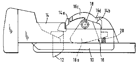
Fig . 1 shows a diagrammatic side view of the f irst
design of the buckle;
Fig. 2 shows a plan view of this buckle;
igs. 3a and 3b show diagrammatic side views of the buckle
to clarify the functioning of the buckle;
Fig. 4 shows a diagrammatic side view of the second
des ign; and
Fig. 5 shows a plan view of the buckle in accord-
ance with this second design.
Fig. 1 shows the main components of a buckle for safety
belts. In a load-bearing frame 10 an insertion path is
provided for an insert tongue. At right angles to this
insertion path a latch 12 is located in a sliding mounting
in the frame 10. When the insert tongue is inserted in the
path, the latch 12 acts through an opening in the tongue.
Furthl- e, on the frame 10 a release button 14 is located

- ~ 21~72~3
-- 3 --
in a longitudinal direction in this frame in a sliding
mounting, and the latch 12 may be pushed into its open posi-
tion by pressing this release button.
Furthermore, a lever 16 is pivotally mounted on the frame 10
around an axis 18. This lever 16 consists of 2 masses 16a
and 16b spaced from each other laterally but rigidly con-
nected to each other through axis 18, and these two masses
together represent a ,- --ting mass. Furthermore, oppo-
site the masses 16a and 16b the lever 16 has two lever arms
16c and 16d.
Two limit stops 14a and 14b are located at the release
button 14, and are spaced from each other in the direction
of the sliding ~ ~, t. of the release button. The distance
is such that the limit stops 14a and 14b are located in the
longitudinal direction of the frame 10 on both sides of the
free ends of the lever arms 16c and 16d so that these free
ends are located opposite the limit stops 14a and 14b and
are located at a short distance from them.
The lever 16 is biased into the initial position shown in
Fig. 1 by a spring 20.
The lever 16 ~ ~n~tes the f orces of inertia occurring at
release button 14 during extreme acceleration or decelera-
tion of the buckle, particularly during the process of seat-
belt tensioning by means of a tensioner which acts on the
buckle and shifts the latter towards the floor of the
vehicle. In case of normal operation of the release button
14 the limit stop 14a strikes the free end of the lever arm
16c, causing the latter to be swivelled in a clockwise
direction. Since the rear limit stop 14b is shifted with the
release button 14, the free end of the lever arm 16d strikes
no obstacle; the release button 14 can therefore be actuated
without hindrance.

2S3
-- 4 --
Fig. 3a shows a diagrammatic view of the forces of inertia
occurring in the case of an acceleration of the buckle in
the direction of an arrow A. Through its inertial force, the
release button 14 tends to shift in the opposite direction
to arrow A. Lever 16, taking into account its lever arms 16c
and 16d as well as the masses 16a and 16b, has a centre of
gravity S. This centre of gravity is located below axis 18.
Lever 16 therefore tends to carry out a counterclockwise
swivelling movement as shown in Fig. 3a. The free end of the
lever arm 16c strikes the limit stop 14a, whereby the move-
ment of the release button 14 is blocked in the opposite
direction to arrow A.
In case of acceleration in the opposite direction B as shown
in Fig. 3b, lever 16 tends to show a clockwise swivelling
m-vt L. Consequently, lever 16, with its force of inertia,
resists a - v L of the release button 14 in the opposite
direction to the acceleration direction B by means of lever
arm 16d, against which limit stop 14b strikes. The release
button 14 is therefore also blocked when extreme accelera-
tion occurs in direction B, which is opposed to direction A.
OV~ tion can be achieved through appropriate dimen-
sioning of masses 16a and 16b, taking into account the
location of the centre of gravity S, so that the blocking
forces produced by lever 16 are greater than the forces of
inertia occurring at release button 14 which have to be
~ V td r ~
In the second ~mho-l;~ L shown in Figs. 4 and 5, a pivoted
latch 12 is also mounted on the frame 10 of the buckle. The
pivoted latch 12 is selectively retained in its closed
position, or released, by a pin-shaped locking element 22,
which has a sliding mounting on a level parallel to the
insertion path of the frame 10. Apart from this indirect
locking of the bolt 12, this buckle corresponds to the
buckle described with reference to first design, and the
function is analogous to that of the version described
above.

Representative Drawing
A single figure which represents the drawing illustrating the invention.
Administrative Status

2024-08-01:As part of the Next Generation Patents (NGP) transition, the Canadian Patents Database (CPD) now contains a more detailed Event History, which replicates the Event Log of our new back-office solution.

Please note that "Inactive:" events refers to events no longer in use in our new back-office solution.

For a clearer understanding of the status of the application/patent presented on this page, the site Disclaimer , as well as the definitions for Patent , Event History , Maintenance Fee  and Payment History  should be consulted.

Event History

Description Date
Inactive: IPC from MCD 2006-03-12
Application Not Reinstated by Deadline 1999-01-15
Time Limit for Reversal Expired 1999-01-15
Inactive: Abandoned - No reply to s.30(2) Rules requisition 1998-05-25
Inactive: Status info is complete as of Log entry date 1998-03-13
Deemed Abandoned - Failure to Respond to Maintenance Fee Notice 1998-01-20
Inactive: S.30(2) Rules - Examiner requisition 1997-11-25
Application Published (Open to Public Inspection) 1996-07-27
All Requirements for Examination Determined Compliant 1996-02-29
Request for Examination Requirements Determined Compliant 1996-02-29

Abandonment History

Abandonment Date Reason Reinstatement Date
1998-01-20
Owners on Record

Note: Records showing the ownership history in alphabetical order.

Current Owners on Record
TRW OCCUPANT RESTRAINT SYSTEMS GMBH
Past Owners on Record
FRANZ WIER
Past Owners that do not appear in the "Owners on Record" listing will appear in other documentation within the application.
Documents

To view selected files, please enter reCAPTCHA code :


To view images, click a link in the Document Description column. To download the documents, select one or more checkboxes in the first column and then click the "Download Selected in PDF format (Zip Archive)" or the "Download Selected as Single PDF" button.

List of published and non-published patent-specific documents on the CPD .

If you have any difficulty accessing content, you can call the Client Service Centre at 1-866-997-1936 or send them an e-mail at CIPO Client Service Centre.


Document
Description 
Date
(yyyy-mm-dd) 
Number of pages   Size of Image (KB) 
Cover Page 1997-04-03 1 16
Abstract 1996-07-27 1 23
Description 1996-07-27 4 171
Claims 1996-07-27 1 33
Drawings 1996-07-27 3 46
Representative drawing 1998-01-30 1 7
Reminder of maintenance fee due 1997-09-16 1 111
Courtesy - Abandonment Letter (Maintenance Fee) 1998-02-17 1 187
Courtesy - Abandonment Letter (R30(2)) 1998-07-20 1 172
Prosecution correspondence 1996-02-29 1 33
Examiner Requisition 1997-11-25 1 33
Courtesy - Office Letter 1996-07-18 1 44
Prosecution correspondence 1996-10-08 4 186
Prosecution correspondence 1996-12-03 4 126