Note: Descriptions are shown in the official language in which they were submitted.
2167q61
FUEL INJECTION PUMP CONTROL
RELATED APPLICATION
Attention is directed to copending application
Serial No. 276,545, filed July 18, 1994.
BACKGROUND OF THE INVENTION
The invention relates generally to internal
combustion engines and, more particularly, to fuel
injector systems for such engines. Still more
lS particularly, the invention relates to solenoid
operated axial flow fuel pumps and to pressure surge
fuel injection mechanisms or valves.
Attention is directed to the following U. S.
Patents:
2,987,293 - Issued June 6, 1961
3,429,552 - Issued February 25, 1969
4,640,391 - Issued February 3, 1987
4,917,351 - Issued April 17, 1990
5,029,807 - Issued July 9, 1991
5,044,563 - Issued September 3, 1991
5,218,999 - Issued June 15, 1993
5,355,856 - Issued October 18, 1994
5,357,933 - Issued October 25, 1994
5,357,g44 - Issued October 25, 1994
Attention is directed to the following foreign
patents:
4-183958 - Japan, issued June 30, 1992
DE 41 07 622 A 1 - Germany, issued October 9, 1992
2167461
.. ~
--2--
SUM~ARY OF THE INVENTION
The invention provides a fuel injection pump
comprising a housing including a wall having therein a
bore, a low pressure fuel chamber communicating with a
source of low pressure fuel, and a high pressure fuel
chamber having a pressure controlled fuel outlet, an
armature structure movably mounted in the housing for
movement in a first direction pressurizing the fuel in
the high pressure chamber and in an opposite direction,
and including a fuel passage communicating between the
low pressure fuel chamber and the high pressure fuel
chamber and including therein a valve seat, an
electrical coil mounted on the housing and operable,
when energized, to cause armature structure movement in
the first direction, a spring located in the housing
and operable, when the coil is deenergized, to cause
armature structure movement in the opposite direction,
a poppet valve slidable within the fuel passage in the
armature structure and relative thereto in response to
movement of the armature structure relative to the
housing and through a stroke length between a first
position permitting flow in the fuel passage from the
low pressure fuel chamber to the high pressure fuel
chamber, and a second position preventing fuel flow
between the high and low pressure fuel chambers, and
comprising a head portion located in the high pressure
fuel chamber and including a valve surface which is
spaced from the valve seat when the poppet valve is in
the first position permitting fuel flow from the low
pressure fuel chamber to the high pressure fuel
chamber, and which is sealingly engaged with the valve
seat when the poppet valve is in the second position
2167~61
preventing fuel flow between the high and low pressure
fuel chambers, an adjustment member extending in the
bore in the housing wall and being engageable with the
poppet valve to control the stroke length thereof
between the fuel flow permitting and fuel flow
preventing positions, and means for displacing the
adjustment member relative to the housing end wall to
variably determine the stroke length of the poppet
valve.
The invention also provides a fuel injection pump
comprising an elongated housing including an end wall
including having therein a central bore, an armature
structure movably mounted in the housing, partially
defining, with the housing, an outer fuel chamber
lS communicating with a source of low pressure fuel,
partially defining an inner fuel chamber having a
pressure controlled fuel outlet, and including a
central bore, a counter bore extending from the central
bore in the direction away from the end wall of the
housing, communicating with the outer and inner fuel
chambers, and including a valve seat between the outer
and inner fuel chambers, and a poppet valve slidable
within the central bore of the armature structure and
relative thereto in response to movement of the
armature structure relative to the housing and through
a stroke length between first position permitting fuel
flow between the outer and inner fuel chambers, and
second position preventing fuel flow between the outer
and inner fuel chambers, and including a head portion
located in the inner fuel chamber and including a valve
surface which is spaced from the valve seat when the
poppet valve is in the first position permitting fuel
flow from the outer fuel chamber to the inner fuel
2167461
chamber, and which is sealingly engaged with the valve
seat when the poppet valve is in the second position
preventing fuel flow between the outer and inner fuel
chambers, an adjustment member extending in the axial
bore in the end wall of the housing and engageable with
the poppet valve, and means for axially displacing the
adjustment member relative to the housing end wall to
variably determine the stroke length of the poppet
valve.
The invention also provides a fuel injection pump
comprising a housing including an elongated wall having
an axis, and an end wall which includes therein an
axial extending bore and which, together with the
elongated wall, partially defines an outer fuel chamber
communicating with a source of low pressure fuel, an
elongated member fixedly extending coaxially with the
elongated wall and including an end spaced from the
housing end wall, an armature structure movably mounted
on the elongated member, defining with the elongated
member an inner fuel chamber having a pressure
controlled fuel outlet, and including a central bore
extending coaxially with the elongated wall, a counter
bore extending from the central bore toward the end of
the elongated member and including a valve seat, and a
fuel passage extending radially between the counter
bore and the low pressure fuel chamber, a poppet valve
including a stem portion slidable within the central
bore of the armature structure and relative thereto in
response to movement of the armature structure relative
to the elongated member and through a stroke length
between a first position permitting fuel flow between
the outer and inner fuel chambers, and a second
position preventing fuel flow between the outer and
2167 161
-
--5--
inner fuel chambers, and a head portion extending from
the stem portion, located in the inner fuel chamber
between the elongated member and the valve seat and
including a valve surface which is spaced from the
valve seat when the poppet valve is in the first
position permitting fuel flow through the fuel passage
and the counter bore from the outer fuel chamber to the
inner fuel chamber, and which is sealingly engaged with
the valve seat when the poppet valve is in the second
position preventing fuel flow between the outer and
inner fuel chambers through the counter bore and the
fuel passage, an adjustment member extending in the
axial bore in the end wall of the housing and
engageable with the stem portion of the poppet valve,
and means for axially displacing the adjustment member
relative to the housing end wall to variably determine
the stroke length of the poppet valve.
The invention also provides a fuel injection pump
comprising a one piece housing member including a
cylindrical wall, an end wall which, together with the
cylindrical wall, defines a low pressure fuel pumping
chamber and which includes therein an axial bore
extending coaxially with the cylindrical wall, a
tubular member fixedly extending coaxially with the
cylindrical wall and including an end spaced from the
end wall of the housing member, an outer surface, and
an interior bore defining a pressure controlled fuel
outlet, an armature assembly including an armature
structure partially defining a high pressure fuel
chamber communicating with the interior bore of the
tubular member and being slideably mounted on the
tubular member for movement in a first direction
pressurizing the fuel in the high pressure fuel chamber
2167961
--6--
and in a second direction opposite to the first
direction, and including a first end adjacent the
tubular member, a second end remote from the tubular
member, an inner bore extending from the first end and
having an inner surface slidingly and sealingly engaged
with the outer surface of the tubular member, a
transverse flange surface extending from the inner bore
in axially spaced relation from the end of the tubular
member, and a bushing located at the second end of the
armature structure and having a central bore extending
coaxially with the cylindrical wall and including an
end axially spaced from the end of the tubular member,
a counter bore extending from the end of the central
bore of the bushing toward the end of the tubular
member and having a valve seat, and a fuel passage
extending radially between the counter bore and the low
pressure fuel chamber, and a poppet valve including a
stem portion having a first end having a transverse
surface remote from the end of the tubular member, an
outer surface extending from the transverse surface in
slidable and sealing engagement with the central bore
of the bushing to afford movement of the poppet valve
relative to the armature structure in response to
movement of the armature structure relative to the
2S tubular member through a stroke length between a first
position permitting fuel flow through the fuel passage
and the counter bore from the low pressure fuel chamber
to the high pressure fuel chamber, and a second
position preventing fuel flow between the high and low
pressure fuel chambers, a second end, and a head
portion located in the high pressure fuel chamber
between the flange surface of the armature structure
and the valve seat and including a valve surface which
2167461
is spaced from the valve seat when the poppet valve is
in the first, fuel flow permitting position and which
is sealingly engaged with the valve seat when the
poppet valve is in the second, fuel flow preventing
position, an adjustment member extending in the axial
bore in the end wall of the housing member and having
an outer end engageable with the end surface of the
plunger, and means for axially displacing the
adjustment member relative to the end wall of the
housing member to variably determine the stroke length
of the poppet valve.
Other features and advantages of the invention
will become apparent to those skilled in the art upon
review of the following detailed description, claims
and drawings.
DESCRIPTION OF THE DRAWINGS
Figure 1 is a fragmentary view of a combined fuel
injection pump and nozzle which incorporates various of
the features of the invention.
Before one embodiment of the invention is
explained in detail, it is to be understood that the
invention is not limited in its application to the
details of the construction and the arrangements of
components set forth in the following description or
illustrated in the drawings. The invention is capable
of other embodiments and of being practiced or being
carried out in various ways. Also, it is understood
that the phraseology and terminology used herein is for
the purpose of description and should not be regarded
as limiting.
2167461
DESCRIPTION OF THE PREFERRED EMBODIMENT
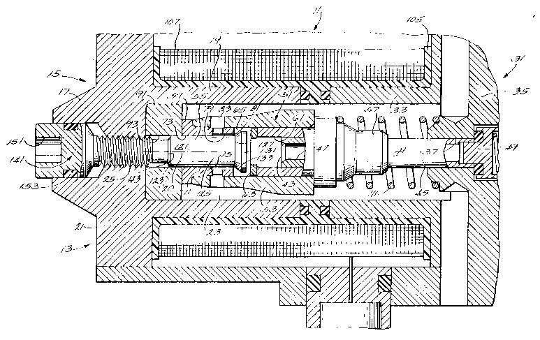
Shown fragmentarily in the drawings is a combined
fuel injection pump and nozzle assembly 11 which, in
general, and except as will appear hereinafter, is in
accordance with the combined fuel injection pump and
nozzle which is disclosed in co-pending application
Serial 276,545, filed July 18, 1994 and which is
incorporated herein by reference. The combined
assembly 11 includes a fuel injection pump 13
comprising a housing assembly 15 including a housing
mem~er 17 which is preferably of one piece construction
and which includes an inner, elongated cylindrical wall
19 having an axis 20. The housing member 21 also
includes an end wall 21 which, together with the
cylindrical wall 19, partially define an outer or low
pressure fuel pumping chamber 23. The end wall 21
includes therein an axial bore 25 extending coaxially
with said cylindrical wall 19.
The fuel housing assembly 15 also includes a
second or other housing member 31 which is also
preferably of one piece construction and which includes
an inner, elongated cylindrical wall 33 which is in
alignment with the inner wall 21. The housing member
31 also includes an end wall 35 which, together with
the cylindrical wall 33, also partially define the
inner or low pressure fuel pumping chamber 23. The end
wall 35 includes therein a central or axial bore 37
extending coaxially with the cylindrical wall 19.
The fuel injection pump 13 also includes a tubular
member 41 which fixedly extends coaxially with the
cylindrical walls 19 and 33 and into and from the axial
or central bore 37 in the end wall 35 of the second
2167~61
housing member 31 and toward the housing member 17.
The tubular member 41 includes an inner end 43 spaced
from the end wall 21 of the housing member 17, an outer
surface 45, and an interior bore 47 including a high
pressure outlet valve 49 defining a fuel outlet.
The fuel injection pump 13 also includes an
armature and valve assembly 51 which includes an
armature structure or member 53 which can be suitably
constructed and is slideably mounted in sealing
engagement on the outer surface 45 of the tubular
member 41 for movement between a low pressure position
and a high pressure position. The assembly 51 also
includes a poppet valve or plunger 55 which is moveable
relative to the armature structure 53 as will be
described hereinafter.
The armature structure or member 53 includes a
first end 57 which is slidable on the tubular member
41, and a second end 59 located remotely to the left in
the drawings from the tubular member 41. The armature
structure 53 also includes an inner or central bore 61
extending from the first end 57 and having an inner
surface slidingly and sealingly engaged with the outer
surface 45 of the tubular member 41. In addition, the
armature structure 53 also includes a transverse flange
surface 63 extending from the inner bore 61 in axially
spaced relation from the inner end 43 of the tubular
member 41 and, in part, defining an inner, high
pressure fuel chamber 65 communicating with the
interior bore 47 of the tubular member 41.
Still further in addition, the armature structure
or member 53 includes, at the second end thereof, a
bushing 71 having a central bore 73 extending coaxially
with the cylindrical walls 19 and 33. The central bore
2167461
--10--
73 includes an end 75 axially spaced from the end 43 of
the tubular member 41, a counter bore 79 extending from
the end 75 of the central bore 73 of the bushing 71 and
toward the end 43 of the tubular member 41 and having a
valve seat 81. The bushing 71 also includes a fuel
passage 83 which extends radially between the counter
bore 73 and the outer, low pressure fuel chamber 23 and
which is located between the end 75 of the central bore
73 and the valve seat 81. The counter bore 79 can also
be considered a part of the fuel passage 83.
Located between the end wall 21 of the housing
member 17 and the end of the armature structure 53
remote from the tubular member 41 is a spacer or member
91 which limits movement of the armature structure 53
to the left in the drawings. The spacer 91 member
includes a central bore 93 permitting passage
therethrough of an adjustment member which is still to
be described and which engages the poppet valve or
plunger 55.
The fuel injection pump 13 also includes, in
surrounding relation to the inner cylindrical walls 19
and 33, a suitable bobbin 105 carrying a solenoid or
coil 107 which, when electrically energized, operates
to displace the armature structure 53 axially along the
tubular member 41 in the direction to the right in the
drawings. A suitable spring 111 biases the armature
structure 53 in the direction to the left in the
drawings and into engagement with the spacer 91 when
the coil 107 is not electrically energized.
The armature and valve assembly 51 also includes
the before mentioned poppet valve or plunger 55 which
includes a stem portion 121 having a transverse end
surface 123 remote from the end 43 of the tubular
2167461
-
--11--
member 41, an outer surface 125 extending to the right
in the drawings from the transverse end surface 123
and in sliding and sealing engagement with the central
bore 73 of the bushing 71 to afford movement of the
plunger or poppet valve 55 relative to the armature
structure 53 in response to movement of the armature
structure 53 relative to the tubular member 41 through
a stroke length between first and second positions.
The stem portion 121 also includes and an end 127
closer to the end 43 of the tubular member 41.
The poppet valve or plunger 53 also includes a
head portion 131 which extends from the end 127 of the
stem portion 121 and which is located in the inner,
high pressure fuel chamber 65 between the flange
surface 63 of the armature structure 55 and the valve
seat 81. The head portion 131 includes, in facing
relation to the valve seat 81, a valve surface 133
which is spaced from the valve seat 81 when the plunger
or poppet valve 55 is in the second position to afford
fuel flow through the fuel passage 83 and the counter
bore 79 from the outer, low pressure fuel chamber 23 to
the inner, high pressure fuel chamber 65 and which is
located in sealing engagement with the valve seat 81 on
the bushing 71 when the plunger or poppet valve 55 is
in the first position to preclude fuel flow between the
low and high prèssure fuel chambers 23 and 65 through
the counter bore 73 and the fuel passage 83.
The fuel injection pump 13 also includes an
adjustment member 141 extending in the axial bore 25 in
the end wall 21 of the housing member 17 and having an
inner end 143 engageable with the end surface 123 of
the plunger or poppet valve 55 to control the stand off
or spacing of the valve surface 133 from the valve seat
2167461
-12-
81 when the armature structure 53 is in the low
pressure position. The stand off distance controls the
amount of movement of the armature structure 55 before
closure of the sealing or valve surface 133 with the
valve seat 81 and hence the amount of transferred
energy.
In this last regard, and in general, the greater
the speed attained by the armature structure 53 before
engagement of the valve surface with the valve seat,
the greater the energy can be transferred to the fuel.
Accordingly, the faster will be the increase in fuel
pressure for delivery through a nozzle (not shown).
In addition, the fuel injection pump 13 also
includes means for axially displacing the adjustment
member 141 relative to the end wall 21 of the housing
member 17 to vary the stand off distance, i.e., to
variably axially locate the second position of the
plunger or poppet valve 55 and thereby adjust the
stroke length of the plunger or poppet valve 55.
While other constructions can be employed, in the
disclosed construction, the adjustment member 141
comprises a screw which is threadedly engaged in the
axial bore 25 in the end wall 21 of the housing member
17 to afford axial movement thereof incident to
rotation thereof. Accordingly, an allen wrench (not
shown) located in a suitable recess 151 in the head of
the screw or adjustment member 141 can be employed to
adjust the stroke of the plunger or poppet valve 55
relative to the armature structure 53 and thereby
control the amount of fuel passing to the inner, high
pressure chamber 65 during each cycle of operation. A
suitable seal 153 can be employed between the end wall
2167461
21 of the housing member 17 and the adjustment member
or screw 141 to prevent escape of fuel therebetween.
As compared to the construction disclosed in
application Serial No. 276,545, the stop member or
adjusting piston thereof has been omitted, whereby
adjustment of the stroke of the armature structure 53
is not directly controlled. Instead, the stroke length
of the poppet valve 55 is controlled by controlling the
amount of movement or the stroke length between the
poppet valve or plunger 55 and the armature structure
or member 53.
As a consequence of the construction disclosed
above, the armature structure or member 53 is moveable
relative to the tubular member 41 in a first direction
(to the right in the drawing) in response to
energization of the electrical coil 107 to pressurize
the fuel in the high pressure fuel chamber 65 and in a
second direction (to the left in the drawing) opposite
to the first direction in response to the action of the
spring 111.
Also as a consequence of the construction
disclosed above, the plunger or poppet valve 55 has a
stroke length between a first, non-engaged or spaced
position wherein the valve surface 133 is spaced from
the valve seat 81 to permit flow from the low pressure
fuel chamber 23 to the high pressure fuel chamber 65 in
response to movement of the armature structure or
member 53 in the second direction, and a second or
engaged position wherein the valve surface 133 is
sealingly engaged with the valve seat 81 to prevent
flow between the low and high pressure chambers 23 and
65. The first or spaced position is determined by
engagement of the left end surface 123 of the plunger
2167461
-14-
or poppet valve 55 with the inner 143 end of the
adjustment screw or member 141.
In operation, energization of the coil 107 causes
movement of the armature structure or member 53 from
the low pressure position and to the right in the
drawings against the action of the spring 111. At the
initiation of such movement of the armature structure
or member 53 from the low pressure position, the
plunger or poppet valve 55 is located in the position
spaced from the valve seat 81, whereby the low pressure
and high pressure fuel chambers 23 and 65 are in
communication through the radial fuel passage 83 and
the counter bore 79. However, such initial movement of
the armature structure 53 to the right effects travel
of the valve seat 81 to the right and into sealing
engagement with the valve surface 133 of the head
portion 131 of the plunger or poppet valve 55. Upon
such engagement, communication of the high pressure
chamber 65 with the low pressure chamber 23 is
terminated and the high pressure chamber is sealed.
Due to the momentum associated with movement of the
armature structure 53 to the right, pressure in the
high pressure chamber 65 increases rapidly until the
pressure operated outlet valve 49 opens, permitting
fuel outflow from the high pressure chamber 65 and
continued armature structure movement to the right.
In this last regard, and in general, the greater
the speed attained by the armature structure 53 before
engagement of the valve surface 133 with the valve seat
81, the greater the energy can be transferred to the
fuel. Accordingly, the faster will be the increase in
fuel pressure for delivery through a nozzle (not
shown).
2167461
-15-
Variation in the amount of fuel pumped from the
high pressure chamber 65 can be obtained by changing
the stroke length of the plunger or poppet valve 55 by
manipulation of the adjustment screw or member 141.
More particularly, if the stroke length of the plunger
or poppet valve 55 between the engaged and non-engaged
positions is lengthened, the armature structure 55 will
move through a greater or increased portion of the
stroke length thereof before the valve seat 81 engages
the valve surface 133 to seal or close the high
pressure fuel chamber 65. Such increased movement
portion before sealing of the high pressure fuel
chamber 65 diminishes the effective volume of the high
pressure chamber 65 and will diminish the quantity of
fuel pumped by the pressure increasing stroke of the
armature structure or member 53 incident to
energization of the coil 107.
Upon deenergization of the coil 107 and completion
of the pressure stroke of the armature structure 53,
the spring 111 will cause armature structure movement
to the left in the drawings to the low pressure
position with the bushing 71 engaged with the spacer
91. Such movement of the armature structure 53 to the
left also carries the poppet valve 55 to the left to
effect, after initial movement, engagement of the end
surface 123 of the plunger or poppet valve 55 with the
adjustment member or screw 141, thereby limiting poppet
valve movement to the left and effecting movement of
the valve seat 81 away from the head portion 131 of the
poppet valve 55 until the bushing 71 engages the spacer
91 to terminate movement to the left of the armature
structure or member 53. Upon disengagement of the
valve seat 81 from the valve surface 133, fuel flows
2167~61
-16-
through the radial fuel passage 83 and through the
counter bore 79, thereby filling the increasing volume
of the high pressure chamber 65 occurring during
armature structure movement to the left. Accordingly,
adjustment of the screw 141 is effective to provide
fine regulation of the amount of fuel pumped incident
to each electrical energization of the coil 107 and
independently of operational control of the engine.
The adjustment member or screw 141 therefore allows
fine tuned control of power balance between the
cylinders of a multI-cylinder internal combustion
engine.
Various of the features of the invention are set
forth in the following claims.