Note: Descriptions are shown in the official language in which they were submitted.
2167777
METHOD AND DEVICE FOR TESTING GAS CARRYING PIPELINES
FIELD OF THE INVENTION
The invention relates to a method for testing gas carrying pipelines by means
of ultrasonics, as well as to a device for testing gas carrying pipelines by
ultrasonics, having a sensor carrier and a scraper sleeve positioned behind the
same and connected thereto.
BACKGROUND OF THE INVENTION
~ltrasonic material testing requires a coupling fluid or liquid. For the ultra-sonic testing of gas carrying pipellnes it is consequently necessary for the
sensors and therefore also a sensor carrier carrying the same to be immersed
in said fluid or liquid. Thus, in the case of a test run of a device for
ultrasonic testing through the gas carrying pipeline it is necessary to carry
along a liquid plug known as a batch. According to the prior art the plug or
batch is carried along in that at a considerable distance upstream and down-
stream of the actual measuring device are carried along separating scrapers
provided with sealing sleeves and which enclose between them the liquid plug
and the ultrasonic measuring device (ultrasonic scraper).
Such a liquid plug or batch must have a considerable length. With standard
distances of several hundred kilometres, the batch length must be 200 to
2000 m. A conventional batch construction has, in front of the actual measur-
ing scraper, four or five separating scrapers with mutual spacings of 20 to
100 m and behind the measuring scraper there are at least two separating
scrapers with a corresponding relative spacing. The distance between the meas-
uring scraper and the next separating scraper upstream thereof is e.g. 200 m
and behind it the following separating scraper is located at a distance of
600 m, so that the total length is approximately 1000 m. In particular the
distance between the measuring scraper and the first following separating
scraper is important, because as a result of the liquid path through the pipe-
line there would otherwise be a risk of the following separating scraper being
pressed during the run against the measuring scraper and as a result the
sensor means located at its rear end would be damaged or destroyed. The
necessarily large liquid quantity for performing a test run is associated with
significant disadvantages, particularly for the pipeline operator. Thus, a
2167777
considerable liquid mass must be introduced into the gas carrying pipeline,
which involves high costs for acquisition and introduction, high costs for the
actual liquid material and high costs for the disposal thereof, because the
liquid is contaminated on forcing through the pipeline.
Therefore the problem of the invention is to provide a method and a device for
testing gas carrying pipelines by ultrasonics avoiding the aforementioned dis-
advantages and in particular permitting the carrying out of the testing with a
much smaller liquid quantity.
SUMMARY OF THE INVENTION
According to the invention the set problem is solved in the case of a method of
the aforementioned type in that an overpressure is produced in a space defined
by the pipeline wall and scraper sleeves and which contains a sensor carrier
with ultrasonic sensors and a coupling liquid. A device according to the inven-tion solves the problem in that a connecting line provided with a pump passes
from an area upstream of the scraper sleeve to an area downstream of said
scraper sleeve.
As a result of the measures according to the invention the sensor carrier of
the device carrying the ultrasonic sensors is always located in a liquid plug
or batch, which has an overpressure with respect to other areas of the carried
along batch, particularly upstream of said scraper sleeve, but also with
respect to following scraper sleeves. This reduces the risk of gas bubbles
forming in the area where the sensor carrier is located. Gas bubbles penetrat-
ing or forming therein can be rapidly moved out of the area by the over-
pressure. This is in particular assisted by the fact that the scraper and/or
sealing sleeves have in their upper area a liquid passage and either the
liquid passage is formed by reducing the material thickness of the scraper
and/or sealing sleeves in their circumferential area or an axial notch is
provided in the upper circumferential sleeve area.
According to another development of the invention, an inlet of the connecting
line issues below a central axis of the device, which increases the probability
of the pump only sucking liquid out of the space upstream of the scraper.
2~67777
-- 3 --
According to another development of the invention the connecting line is guided
by two spaced, succeeding scraper sleeves both located upstream of the sensor
carrier. In preferred manner there are sealing sleeves located behind and
axially connected to the sensor carrier. If the sealing sleeves following the
sensor carrier are connected thereto by a rigid, axial device (even though
jointed movable), then a running up or abutting of the sealing sleeves on the
sensor carrier and therefore damage thereto is avoided.
Due to all these measures the length of the batch to be carried along can be
considerably reduced. A typical total device for the batch required in the
device according to the invention from the furthest forward separating scraper
to the rear sealing sleeve is approximately 50 to 100 m for roughly the same
length of run as mentioned hereinbefore.
BRIEF DESCRIPTION OF THE DRAWINGS
Further advantages and features of the invention can be gathered from the
claims and the following description of an embodiment of the device according
to the invention with reference to the single drawing showing a preferred con-
struction of the device for testing gas carrying pipelines according to the
invention.
DETAILED DESCRIPTION OF THE EMBODIMENT
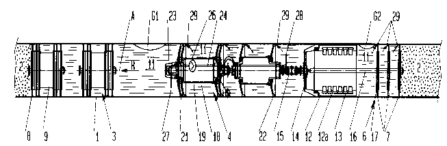
The drawing shows a pipeline 1 carrying a gas 2. If the pipeline is to be
ultrasonically tested for faults such as corrosion, cracks, etc., then in per
se known manner a separating scraper 3 is provided. In the flow direction R of
the gas behind the separating scraper 3 is provided a device for testing gas
carrying pipelines 1 according to the invention, or an ultrasonic scraper 4
f or short. In the represented embodiment the scraper 4 carries on its end
(at 6) which is at the rear in the flow direction R and remote from the separ-
ating scraper 3, sealing sleeves 7, here in the form of sealing disks.
The separating scraper 3 also has sealing sleeves or disks 8, as well as a
sleeve carrier 9 carrying the same. Between the separating scraper 3 and the
sealing sleeves 7 is provided a liquid 11 as the coupling medium for the ultra-
2i6~777
sonics used for testing the pipeline. The sealing sleeves 7, 8 seal the liquidforming a plug in the pipeline 1 with respect to the gas 2 conveyed through the
pipeline 1 upstream of the separating scraper 3 and downstream of the sealing
sleeves 7.
Such an arrangement with a liquid plug or batch with respect to the sealing
sleeves to be sealed against the surrounding gas and a measuring or test
scraper located between them is referred to hereinafter as a batch.
The device according to the invention, i.e. the scraper 4, has a sensor carrier
12 with ultrasonic sensors 13. The sealing sleeves 7 are connected in jointed
manner by means of a joint 14 to the sensor carrier 12, but with a fixed axial
spacing, which is defined by a carrier rod 16 on which is firmly positioned the
rigid disks 17 carrying the sleeves 7. The sensor carrier 12 with the sensors
13 is constructed in per se known manner, such as is e.g. known from EP 255 619.
Upstream of the sensor carrier 12 and connected thereto by means of a joint 15
is a sleeve carrier 18, which can contain in a casing 19 e.g. all the elec-
tronics, storage media, etc. In the represented embodiment the sleeve carrier
18 carries two scraper sleeves 21, 22. At its front end (in the flow direction
R) it is provided with a run-up or abutting protection means 23, which prevents
damage to the components of the scraper 4 if the liquid between it and the
separating scraper 3 during the operation of the scraper is reduced to such an
extent that the test scraper 4 strikes against the separating scraper 3.
From the area upstream of the front scraper sleeve 21 to the area behind the
rear scraper sleeve 22 (considered in the flow direction R) extends a connec-
ting line 24 containing a pump 26, which pumps liquid through the connecting
line from the area between the separating scraper 3 and the front scraper
sleeve 21 into the area between the rear scraper sleeve 22 and the rear sealing
sleeves 7, in which is located the sensor carrier 12 with the ultrasonic sen-
sors 13.
The intake 27 of the connecting line 24 is located in a lower area of the
pipeline 1 or the measuring scraper 4 and certainly below the symmetry axis A
of the pipeline 1 or scraper 4. The outlet 28 of the connecting line 24 is in
216~777
the area between the rear scraper sleeve 22 and the front sealing sleeves 7.
At 29 the scraper and sealing sleeves 21, 22, 7 have no liquid passages. They
can be formed by weakening the sleeve circumference or a small V-shaped notch
in the circumferential area of the sleeves 7, 21, 22.
The drawing also shows gas bubbles G1 and G2. It is pointed out that the
sensor carrier 12 in its axially parallel area 12a, which carries the sensors
13, can either have longitudinal grooves in the outer area or the carrier can
be constructed as individual fingers or arms with radial openings between them.
During the operation of the complete means 3, 4 liquid is permanently pumped by
the pump 26 from the space upstream of the test scraper 4 into the space around
the sensor carrier 12 with its sensors 13 and an overpressure is built up in
said space. Due to the fact that the liquid is sucked via the intake 27 in
the lower area of the pipeline 1 and the said overpressure is produced in the
vicinity of the sensor carrier, it is ensured that in the latter there are no
gas bubbles or the gas bubbles which occur, such as the gas bubble G2, are
forced out of the space surrounding the sensor carrier 12 through the weakening
areas 29 of the sleeves 22, 21 and 7. It is thereby ensured that the gas
bubbles do not stop along the space surrounding the sensor carrier 12 and in
particular between the sensors 13 and the wall of the pipeline 1 and therefore
make difficult or even impossible for a long period time the measurements and
tests. In addition, through the overpressure produced in the described manner
in the space surrounding the sensor carrier 12 it is ensured that no gas
bubbles, such as a gas bubble G1, can penetrate the liquid upstream of the
device or scraper 4 according to the invention. Such gas bubbles G1, G2 can be
formed through branches in the pipeline into which water can be splashed
during the moving past of the device, so that gas is carried along in the batch.
Due to the indicated measures and the resulting gas bubble check, it is ensured
that all the coupling liquid carried along through the device for a predeter-
mined distance can be much smaller than is the case in conventional ultrasonic
testing devices for gas carrying pipelines, where there are several separating
scrapers upstream and downstream of the testing device must have a larger
spacing. As a result of the axially fixed connection of the rear sealing
2167777
-- 6 --
sleeve 7 with the testing device a significantly greater liquid extension
length behind the measuring device 4 is avoided, this being needed in the
known devices to prevent a running up of the rear separating scrapers onto the
test scraper, because this could lead to the destruction thereof.