Note: Descriptions are shown in the official language in which they were submitted.
21679~J7
TITLE:
BAR CLEANER FOR TRASH BAG BREAKER
FIELD OF THE INVENTION
The present invention relates generally to municipal waste processing
systems and more particularly to an apparatus for opening garbage bags.
BACKGROUND OF THE INVENTION
Refuse from individuals and businesses is oKen placed in plastic
garbage bags for disposal. Such bags are used by consumers when the
weekly accumulation of trash exceeds the space available in the one or two
trash containers typically owned by a suburban dweller. In other instances,
for persons who are not on a garbage route, the trash must be transported to
a waste facility. In such circumstances, a per bag fee may be charged for
dumping and thus trash bags will be the normal method of delivery of the
trash. Transporting trash in trash bags is more secure than in trash cans as
they cannot tip over. Further, the trash is sealed within the bag and there is
no need to transport the sometimes soiled and smelly trash containers back
from the disposal site. In yet other circumstances, municipal plans for
recycling may require that certain types of recyclable materials such as
aluminum cans, plastic bottles and glass bottles be placed in a clear plastic
bag for identification and collection.
For proper functioning in the collection and handling of refuse, a
plastic garbage bag needs to be burst and tear resistant. If the bag is easily
burst or torn, the bag may spill its contents before reaching the waste
disposal site. The premature breaking of a garbage bag often results in the
wind disposal of large quantities of litter. If a bag bursts while being
transported, the car or truck transporting the bag may become soiled and the
--1--
216~997
- EF089581 485US
owner of the bag may be subject to considerable penalties for littering along
the highway.
When municipalities were aliowed to landfill the entire volume of
collected municipal waste, the high tear or burst resistance of garbage bags
was of little or no concern. However, where efforts are made to recycle
substantial portions of the municipal waste stream, it is necessary to open
the garbage bags in order to separate out the constituents of the trash. This
is particularly essential when the plastic bags contain only recyclable
materials as a part of a program to segregate recyclable trash in specially
designated plastic bags.
To deal with the difficulty of opening garbage bags, a number of
devices have been developed. A device for opening garbage bags employs
a multiplicity of bars or tines which are mounted on chains or belts and
traverse an endless path about spaced apart sprockets or rollers. The bars
are arrayed to penetrate the trash bag with adjacent and/or opposed bars
being driven at different speeds to rip the trash bags apart.
Such bag bursting apparatuses are relatively effective. However, the
bars which are used to penetrate the bags will not infrequently also penetrate
or impale one or more items of garbage, for example, an aluminum can or
plastic bottle. Even shreds of plastic bag which become wound around or
impaled upon the bars can, as material builds up over time, impede the
function of the bag opener or even cause it to jam. When the bars become
sufficiently burdened with wastes, the unit must be shut down and the bars
cleaned by hand. This can be a time consuming and dirty job.
What is needed is an apparatus for cleaning the bars on a bag
breaker.
216 f ~7
EF089581 485US
SUMMARY OF THE INVENTION
The bag breaker bar cleaners of this invention are of two types. The
first type employs a comb structure in which a multiplicity of teeth are
mounted to a beam. The spaces between the teeth define slots. The edges
of the slots are lined with upstanding flanges which are sharpened to form
cutting edges. The comb structure is arranged to be substantially parallel to
an array of bag breaking bars which traverse a closed loop. The bars
arrayed on the plurality of parallel chain drives interdigitate with the teeth.
When the bars pass through the narrow openings between the comb teeth,
the knife edges scrape opposed surfaces of the bars and cut free any
material adhering to or impaled upon the bag breaking bars.
The second embodiment of the apparatus for cleaning the bars of a
bag breaking apparatus of this invention is an arm pivotally mounted at a
point hxed with respect to the endless loop formed by a chain on which bars
are mounted. A fork two or more tines.is mounted on the arm and is aligned
to receive a bar between its tines. The fork engages the base of the bar and
then proceeds to slide up the bar as the forward motion of the bar on the
chain causes the arm to pivot about its pivot point. In this way, material
impaled upon a bar is slid or scraped upwardly towards the top of the bar.
When the fork reaches the top of the bar and has thus removed any material
impaled upon the bar, it pivots in response to an attached spring back to its
initial position wherein it engages the next bar in sequence.
It is a feature of the present invention to provide an apparatus for
cleaning the bars of a trash bag breaker.
It is another feature of the present invention to provide an apparatus
which shears material which has become impaled or entangled with the bars
of a trash bag breaker.
2167997
EFO89581 485US
It is a further feature of the present invention to provide an apparatus
for cleaning the bars of a trash bag breaker which slides material impaled or
entangled with the bars off the bars.
Further objects, features and advantages of the invention wiil be
apparent from the following detailed description when taken in conjunction
with the accompanying drawings.
BRIEF DESCRIPTION OF THE DRAWINGS
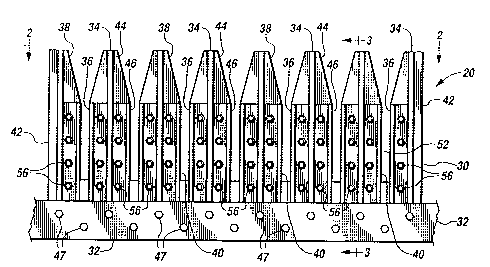
FIG. 1 is a top plan view of a bag breaker bar cleaner of the present
invention.
FIG. 2 is an end elevational view of the bar cleaner of FIG. 1 taken
along line 2-2.
FIG. 3 is a cross-sectional view of the bar cleaner of FIG. 1 taken
along section line 3-3.
FIG. 4 is a schematic view showing how the bar cleaner of FIG. 1 may
be positioned to clean the bars of a bag breaker apparatus.
FIG. 5 is a schematic view showing an alternative positioning of the
bar cleaner of FIG. 1 for cleaning the bars of a bag breaker apparatus.
FIG. 6 is an illustrative side-elevational view of an alternative bag
breaker bar cleaner of this invention.
FIG. 7 is a side-elevational view similar to FIG. 6 wherein the sliding
progression of the cleaner fork along the bag breaker bar is illustrated.
FIG. 8 is an enlarged fragmentary isometric view of the bag breaker
fork of FIG. 6 sliding along a bag breaker bar.
DESCRIPTION OF THE PREFERRED EMBODIMENTS
Referring more particularly to FIGS. 1-8, wherein like numbers refer to
similar parts, a bag breaker bar cleaner 20 is shown in FIGS. 1-3.
Bag breakers 22 such as those shown in FIGS. 4 and 5 typically
employ bars 24 which are mounted to an endless chain 26 which traverses a
--4--
2 1 1~ 7
EFO89581 485US
closed loop about one or more sprockets 28. While bag breakers come in a
number of configurations, those employing bars typically use the bars to
impale or penetrate bags of trash. The parallel rows of adjacent bars (not
shown) are driven at different speeds so that when the trash bag is impaled
by two or more bars moving at different speeds, the bag containing the trash
is torn open.
As the bars 24 rotate around a sprocket, as shown in FIGS. 4 and 5,
the bars reverse direction, going from pointing up to pointing down or vice
versa. This inversion of the bars can be used to cause the bars to penetrate
or impale bags of trash. The bars are typically designed to be sufficiently
sharp so as to penetrate the trash bags but have blunted tops, as shown in
FIG. 8, so as to avoid impaling or penetrating individual items of trash.
However, invariably, items of trash become impaled upon or wrapped around
the bars 24.
A bar cleaner 20 may be employed to automatically clean the bars. As
shown in FIG.1, the bar cleaner 20 has a comb-shaped structure 30 which
has a support beam 32 which supports the bar cleaner 20 approximately
perpendicular to the direction of motion of the bag breaker 22. The bar
cleaner has a multiplicity of teeth 34. Each tooth 34 has a rectangular
portion 36 and a tapered section 38. Adjacent rectangular portions 36 define
slots 40 which are sized to narrowly pass bars 24.
The teeth 34 are cut from a plate 42 and are stiffened by gussets 44
which are welded to the plate 42. The plate 42 is bolted to the beam 32 by
bolts 47. Each gusset 44 stiffens a tooth 34. Mounted on either side of the
gusset 44 and aligned with the edges 46 of the slots 40 are right-angle
cutting flanges 48 The cutting flanges have upstanding legs 50 which
terminate in a cutting edge 52 which is part of a blade surface 54. Thus the
sides 46 of the slots 40 have sharp edges 52 which shear material off the
bars 24 as they interdigitate with the teeth 34 passing through the slots 40.
--5--
21~79~7
EFO89581 485US
The tapered portions 38 of the teeth 34 help to center the bars 24 and guide
them into the slots 40.
Because the support beam 32 will often form part of the structure of
the bag breaker 22, the plate 42 is releasably bolted by bolts 47 to the beam
32. The cutting flanges 48 are removably attached to the teeth 34 by bolts
56. The cutting flanges 48 may require periodic removal for replacement or
sharpening and this is facilitated by the bolts 56 which allow the disassembly
and removal of the cutting flanges 48 from the teeth 34.
As the bars 24 traverse about the sprockets 28 on the endless chain
26, they sweep out a closed volume. The cleaner assembly 20 is designed
to bracket and surround this closed volume with sharp edges which shear off
any material which has increased the width of the bars 24 by adhering
thereto. As shown in FIGS. 4 and 5, depending on the direction of rotation of
the chain about the sprocket, the placement of the bar cleaner assembly 20
will vary so that the bars travel into the sharpened edges 52 and so that the
material sheared from the bars readily falls clear of the bag breaker 22 and
the bar cleaner 20. The bar cleaner 20 will be angled downwardly, as shown
in FIG. 4 to cleans bars which are traveling upwardly, and will be angled
upwardly, as shown in FIG. 5, to clean bars which are traveling downwardly.
It should be understood that the bar cleaner 20 should be positioned
with respect to the bars 24 so that the bars engage with the base 25 first.
The base passes between opposed tapered portions 38 of the teeth 34. In
this way the tapered portions center the bars in the slots 40. The cutting
flanges 48 create a shearing action with the sides of the bars similar to a pairof scissors which shears off the material adhering to the bars 24.
An alternative embodiment bag breaker bar cleaner assembly 120 is
shown in FIGS. 6-8 mounted to a bag breaker 122. The bar cleaner 120
cleans the bag breaker bars 124 by sliding material from the bar base 125 to
--6--
21~ ~ 9~7
EF089581 485US
the bar top 127. This sliding action is accomplished by a plurality of pivotablearms, the number of which will depend on the number of rows of bag
breaking bars employed in a particular apparatus. Each arm 129 pivots about
a pivot axis 131. The pivot axis 131 is fixed with respect to the path
traversed by the bars 124. The arm 129 supports a fork 133 which is formed
at the end of the arm opposite the pivot axis 131. The fork 133 has two tines
135 which define a U-shape.
In an initial position, shown in FIG. 6, the fork 133 is engaged at the
bottom 125 of the bar 124. The fork, as shown in FIG. 8, engages three
sides 137,139 and 141 of the bar 124. As shown in FIG. 6, the arm 129
rotates about the pivot axis 131 so that the fork 133 follows a circular path
143. The bar top 127 follows a curved path 145 as it turns around the
sprocket 128 as shown in FIG. 6. Motion of the chain 126 carries the bars
124 around the sprockets 128.
Where a bar 124 becomes engaged with a fork 133 of the arm 129,
the forward motion of the bar 124 causes a fork 133 to slide up the bar 124
from the base 125 to the top 127. As shown in FIGS. 6 and 7, where the
path 143 of the fork and the path 145 of the bar tips intersect at a point 147,
the arm 133 passes over the top 127 of the bar, whereupon a spring 149
causes the arm to return to its initial position as shown in FIG. 6 where it
causes the next bar in sequence to be scraped.
It should be understood that the bar cleaners 20 and 120 may be
employed with bag breaking apparatus of varying configurations.
It should also be understood, for purposes of this application, the
endless chain referred to as 26,126 is defined to include such structures as
a plate conveyor, a conventional conveyor belt or other types of belts on
which bars 24 may be mounted and caused to follow an endless path about
216 1 39~
-- EF08958 1 485US
one or more sprockets. It being further understood that the term sprockets
includes pulleys, rolls, or wheels about which an endless chain moves.
Again, it should be understood that the bag breaking apparatus may
be configured with one, two, three or more sprockets over which the endless
chain moves. It should be understood that the bag breaking apparatus 22
and 122 illustrated in FIGS. 4, 5, 6 and 7 illustrate only a portion of the bag
breaking apparatus and that normally a number of chains with bars will be
arrayed in spaced parallel relation with alternate chains and bars moving at
varying speeds so that when a bag of trash is impaled by two adjacent bars
moving at different speeds, the bag will be torn open.
It is understood that the invention is not limited to the particular
construction and arrangement of parts herein illustrated and described, but
embraces such modified forms thereof.as come within the scope of the
following claims.