Language selection

Search

Patent 2168025 Summary

Third-party information liability

Some of the information on this Web page has been provided by external sources. The Government of Canada is not responsible for the accuracy, reliability or currency of the information supplied by external sources. Users wishing to rely upon this information should consult directly with the source of the information. Content provided by external sources is not subject to official languages, privacy and accessibility requirements.

Claims and Abstract availability

Any discrepancies in the text and image of the Claims and Abstract are due to differing posting times. Text of the Claims and Abstract are posted:

  • At the time the application is open to public inspection;
  • At the time of issue of the patent (grant).
(12) Patent Application: (11) CA 2168025
(54) English Title: METHOD FOR SHORT-CIRCUIT CURRENT LIMITING ON AN ELECTRICAL POWER TRANSMISSION LINE, AND AN ARRANGEMENT FOR SHORT-CIRCUIT LIMITING
(54) French Title: METHODE POUR LIMITER LE COURANT DE COURT-CIRCUIT SUR UNE LIGNE DE TRANSMISSION D'ELECTRICITE, ET ARRANGEMENT CORRESPONDANT
Status: Deemed Abandoned and Beyond the Period of Reinstatement - Pending Response to Notice of Disregarded Communication
Bibliographic Data
(51) International Patent Classification (IPC):
  • H2H 9/02 (2006.01)
  • H2J 3/04 (2006.01)
(72) Inventors :
  • MULLER, WALTER (Germany)
(73) Owners :
  • SIEMENS AKTIENGESELLSCHAFT
(71) Applicants :
  • SIEMENS AKTIENGESELLSCHAFT (Germany)
(74) Agent: SMART & BIGGAR LP
(74) Associate agent:
(45) Issued:
(86) PCT Filing Date: 1994-07-13
(87) Open to Public Inspection: 1995-02-02
Examination requested: 1996-01-24
Availability of licence: N/A
Dedicated to the Public: N/A
(25) Language of filing: English

Patent Cooperation Treaty (PCT): Yes
(86) PCT Filing Number: PCT/DE1994/000806
(87) International Publication Number: DE1994000806
(85) National Entry: 1996-01-24

(30) Application Priority Data:
Application No. Country/Territory Date
P 43 25 061.0 (Germany) 1993-07-26

Abstracts

English Abstract


In order to obtain an improved operating behavior
relative to the prior art in the event of short circuits
on a high-voltage line (3) having a phase shifter (8), it
is provided for the phase shifter (8) to be used as a
current limiter in the event of a fault. A fault signal,
which results in an opposing voltage on the additional
transformer (7) of the phase shifter (8) being increased,
is produced for this purpose, as a function of the fault
current.


French Abstract

Afin de maintenir, en cas de courts-circuits sur une ligne haute tension (3) pourvue d'un déphaseur, une meilleure tenue en service par rapport à l'état actuel de la technique, il est prévu d'utiliser le déphaseur (8) comme limiteur de courant en cas de défaut. Un signal d'erreur produit en fonction du courant de défaut provoque une augmentation d'une contre-tension sur le transformateur additionnel (7) du déphaseur (8).

Claims

Note: Claims are shown in the official language in which they were submitted.

- 6 -
claims
1. A method for short-circuit current limiting on an
electrical transmission line in which one of the windings
of a transformer is connected, by means of which winding
the current on the transmission line is limited, and in
which case the short-circuit current limiting on the
transformer is activated by a control device (9), charac-
terized
- in that a fault signal is passed from a protective
device (12a, 12b, 13) to the control device (9) for
activation of the short-circuit current limiting on
the occurrence of a short circuit on a transmission
line which is designed as a high-voltage line (3), and
- in that the transformer is an additional trans-
former (7) of a phase shifter (8), the control
device (9) supplying to the additional transformer (7)
power which is provided by an energizer trans-
former (11), and an opposing voltage being produced at
the additional transformer (7) on the high-voltage
line (3) in the sense of short-circuit current limit-
ing, with an in-phase, quadrature-phase or phase-
shifted voltage.
2. The method as claimed in claim 1, characterized
in that the fault direction and/or the fault location of
the short circuit are/is detected by the protective
device (12a, 12b, 13) and are/is encrypted in the fault
signal, a suitable opposing voltage being produced as a
function of the fault direction.
3. The use of an additional transformer (7), which
is connected in a high-voltage line (3), of a phase
shifter (8), for phase-shifted, in-phase or quadrature-
phase regulation as a current limiter, the high-voltage
line (3) being monitored by a protective device (12a,
12b, 13) for any short circuit and a fault signal being
produced on identification of a short-circuit current,
which fault signal is supplied to a control device (9) of

- 7 -
the additional transformer (7) for producing an opposing
voltage at the additional transformer (7) in the sense of
current limiting.
4. An arrangement for short-circuit current limiting
on an electrical transmission line in which one of the
windings of a transformer is connected, by means of which
winding the current on the transmission line is limited,
a control device (9) being provided for activation of
short-circuit current limiting, characterized
- in that the transformer is a converter-controlled
additional transformer (7) of a phase shifter (8) with
an energizer transformer (11) for phase-shifted,
quadrature-phase or in-phase regulation of the power
on the transmission line,
- in that the transmission line is a high-voltage
line (3), and
- in that a protective device (12a, 12b, 13) is provided
for detection of a short circuit on the high-voltage
line (3),
- a fault signal being passed to the control device (9)
of the additional transformer (3) on detection of a
short circuit by the protective device (12a, 12b, 13),
and an opposing voltage being produced at the addi-
tional transformer (7) on the high-voltage line (3),
in the sense of short-circuit current limiting, with
an in-phase, quadrature-phase and phase-shifted
voltage.
5. The arrangement as claimed in claim 4, charac-
terized in that the protective device (12a, 12b) is a
distance protective device or an overcurrent protective
device.
6. The method as claimed in claim 4 or 5, charac-
terized in that the phase shifter (8) has a converter (9)
for supplying the additional transformer

- 8 -
(7), and the converter (9) comprises the control device.
7. The arrangement as claimed in claim 6, charac-
terized in that the converter (9) is designed as a
semiconductor converter having an intermediate circuit.

Description

Note: Descriptions are shown in the official language in which they were submitted.


0 2 S
GR 93 P 3380 P
, . ~ ~,. . , , i
L~
Description
Method for short-circuit current limiting on an
electrical power transmission line, and an arrangement
for short-circuit limiting
In order to protect electrical power transmission
lines in the event of short circuits, it is known for
protective devices, for example a distance protective
device or an overcurrent protective device, to be used at
the ends of said power transmission lines. If a short
circuit occurs, then the faulty line is disconnected by
the power circuit breakers which are located at its ends.
The power transmission is then completely interrupted.
This is not absolutely essential, particularly in the
case of grid networks.
It is known for a regulating arrangement having
a transformer set to be used for the coupling of electri-
cal grids (Elektrizitatswirtschaft [Electricity Economy],
Year 86 (1987), Issue 4, pages 123 to 128). Such a
transformer set comprises an additional transformer which
is connected in the electrical transmission line and is
supplied with power from an energizer transformer in
order to produce an in-phase or quadrature-phase voltage
on the line. Such a transformer set has the task of
compensating for phase shifts between the grids, it being
possible to influence the power to be transmitted. It is
therefore also called a phase shifter. In the event of a
short circuit, a considerable short-circuit current flows
via the additional transformer in such an arrangement.
This is undesirable.
If the regulating arrangement is equipped with a
semiconductor converter for driving the additional
transformer, the ~; cn~ioning of the semiconductor valves
is governed by the maximum value of the network short-
circuit current, which is influenced only by the selec-
tion of the short-circuit voltage of the additional
transformer. Load-flux control becomes more effective the
smaller the short-circuit voltage of the additional
transformer is chosen to be. One

GR 93 P 3380 P ~ fi ~2~ 5
design of the regulating arrangement with semiconductors
i8 known from IEEE SPECTRUM, April 1993, pages 40 to 45.
The invention is based on the object of specify-
ing a method and an arrangement for short-circuit limit-
ing on an electrical power transmission line, in the caseof which method and arrangement improved grid operation
is possible while avoiding the disadvantages mentioned
above.
In terms of the method, the object is achieved
according to the invention by a method for short-circuit
current limiting on an electrical transmission line in
which an additional transformer is connected in order to
produce an in-phase, quadrature-phase or phase-shifted
voltage and which is monitored for any short circuit, a
fault signal being passed, if a short-circuit occurs, to
a control device of the additional transformer for
producing an opposing voltage, in particular an in-phase,
quadrature-phase or phase-shifted voltage, at least in
the sense of current limiting.
In terms of the arrangement, the object is
achieved according to the invention by an arrangement of
a converter-controlled additional transformer for produc-
ing an in-phase, quadrature-phase and phase-shifted
voltage on an electrical transmission line, having means
for detection of a short circuit on the transmission
line, which means pass a fault signal, on identification
of a short circuit, to a control device of the additional
transformer, the additional transformer being used as a
current limiter, increasing the voltage produced on the
transmission line.
Although the requirements with respect to damage
prevention are similar for protection of the line and for
protection of the additional transformer, these two
problems have until now always been dealt with
separately.

~ l~80~
GR 93 P 3380 P - 3 -
The invention is based on the observation that
converter-controlled phase shifters having a transformer
set have a very favorable time response. A completely
novel type of control has been developed which allows the
phase shifter to be used virtually as a short-circuit
current limiter between supply networks. In consequence,
the arrangement protects itself and, furthermore, other
parts of the supply networks against effects of short-
circuit currents. Since the additional transformer is in
this way used in the sense of a power circuit breaker,
the circuit complexity, in high-voltage engineering
terms, on the additional transformer can also be kept
low, if required. Specifically, there is no longer any
need for any power circuit breakers to be provided for
it. Isolating switches are sufficient. The
interconnection of the supply networks in power terms is
then carried out by controlling the converter on the
additional transformer.
In this case, it is particularly advantageous
that the power semiconductors, in particular the thyris-
tors or GT0 thyristors, can be utilized to a far greater
extent, since the short-circuit current amplitude in the
converter intermediate circuit can be limited to a lower
value. It is then possible to operate with a reduced
number of thyristors, with an intermediate-circuit
voltage which is then appropriately matched.
Furthermore, the present solution is a step in
the direction of integrated protective technology for
power transmission, in which optimum protection is
achieved by coupling of the individual components. The
invention can also advantageously be used in the case of
future power distribution grids in which superconduction
will be used. Specifically, in the case of the present-
day prior art, such applications are possible only using
the principle of controlled "quenching".
Further advantageous embodiments are specified in
the other claims. The invention and further details
[lacuna].

2:168025
GR 93 P 3380 P - 4 -
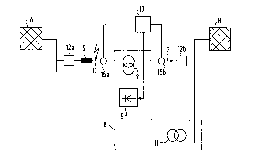
FIG 1 shows a grid arrangement having a phase shifter,
and
FIG 2 shows an associated voltage vector diagram.
Two electrical supply networks A and B can be
seen in FIG 1, which are connected to one another via an
electrical line 3, in particular a high-voltage line. The
associated line inductance is designated by 5. An addi-
tional transformer 7, which is used as the power section
of a phase shifter 8, is connected in the line 3, in
series. It is controlled by a converter 9 (having an
intermediate circuit) with an associated energizer
transformer 11. The converter 9 is designed as an
intermediate-circuit converter having semiconductor
components, in particular having power semiconductor
components, for example GT0 thyristors.
If a short circuit now takes place on the line 3
at the point C, then a not insignificant part of the
short-circuit current flows from the supply network B via
the additional transformer 7 into the short circuit.
Under some circumstances, reliable initiation of the grid
protective devices 12a, 12b, which are arranged at the
end of the line 3, is not ensured. The additional trans-
former 7 must carry the short-circuit current.
A fault detection device 13 is electrically
assigned to the converter 9, which fault detection
device 13 detects the location and/or the direction of
the short circuit via suitable measuring sensors
15a, 15b, and emits an appropriate fault signal or
comm~n~ to a control device, which is not shown in more
detail, of the converter 9. If required, the direction
can be included in encrypted form in the fault signal.
The fault detection device 13 can also be part of the
converter 13. The converter 9 then immediately limits (or
cuts off) the power on the next zero crossing of the
voltage at the additional transformer 7, as a result of
which the power supply for the short circuit from the
supply network B is immediately interrupted. If required,
the information about the fault location and/or the
direction of the short circuit can be made available by
already existing protective devices on the line, for
example by the existing

~168U~S
GR 93 P 3380 P - 5 -
grid protective devices 12a, 12b. The device 13 can then
be omitted. Distance protection or overcurrent protection
are used, for example, as grid protective devices
12a, 12b.
FIG 2 shows a single-pole voltage vector diagram
for the case of a short circuit in the supply network A.
The voltage UA has in this case been collapsed with
respect to the voltage UB by the short circuit. The
additional voltage Uz is fed in via the additional trans-
former 7, by the phase shifter 8.
Use of the phase shifter 9 as a short-circuit
current limiter results in the direct advantage for the
phase shifter 8, in particular its converter 9, itself
that the power semiconductor components which are
designed, for example, for a steady-state continuous
current f IN = lkA in the case of a surge short-circuit
current amplitude in the intermediate circuit of 25 kA,
can be utilized to a far greater extent if the short-
circuit current amplitude is limited, for example, to
2 x IN~ In this case, a continuous current of, for
example, IN = 3 kA could then be acceptable. As a result
of this, it is now possible to operate with a third of
the previously required number of thyristors, with an
appropriately matched intermediate-circuit voltage,
because of the series connection of the power
semiconductors.
If a phase shifter for a high-voltage line
already exists, then only detection of the short-circuit
location and/or of the short-circuit current, and appro-
priate control matching in the converter of the phaseshifter, are required for implementation of the indicated
arrangement. If the phase shifter is equipped with a
computer, then this can be done simply by adaptation of
the control software.

Representative Drawing
A single figure which represents the drawing illustrating the invention.
Administrative Status

2024-08-01:As part of the Next Generation Patents (NGP) transition, the Canadian Patents Database (CPD) now contains a more detailed Event History, which replicates the Event Log of our new back-office solution.

Please note that "Inactive:" events refers to events no longer in use in our new back-office solution.

For a clearer understanding of the status of the application/patent presented on this page, the site Disclaimer , as well as the definitions for Patent , Event History , Maintenance Fee  and Payment History  should be consulted.

Event History

Description Date
Inactive: IPC from MCD 2006-03-12
Application Not Reinstated by Deadline 2000-07-13
Time Limit for Reversal Expired 2000-07-13
Deemed Abandoned - Conditions for Grant Determined Not Compliant 1999-11-18
Deemed Abandoned - Failure to Respond to Maintenance Fee Notice 1999-07-13
Notice of Allowance is Issued 1999-05-18
4 1999-05-18
Letter Sent 1999-05-18
Inactive: Status info is complete as of Log entry date 1999-05-12
Inactive: Application prosecuted on TS as of Log entry date 1999-05-12
Inactive: Approved for allowance (AFA) 1999-05-04
All Requirements for Examination Determined Compliant 1996-01-24
Request for Examination Requirements Determined Compliant 1996-01-24
Application Published (Open to Public Inspection) 1995-02-02

Abandonment History

Abandonment Date Reason Reinstatement Date
1999-11-18
1999-07-13

Maintenance Fee

The last payment was received on 1998-06-17

Note : If the full payment has not been received on or before the date indicated, a further fee may be required which may be one of the following

  • the reinstatement fee;
  • the late payment fee; or
  • additional fee to reverse deemed expiry.

Patent fees are adjusted on the 1st of January every year. The amounts above are the current amounts if received by December 31 of the current year.
Please refer to the CIPO Patent Fees web page to see all current fee amounts.

Fee History

Fee Type Anniversary Year Due Date Paid Date
MF (application, 3rd anniv.) - standard 03 1997-07-14 1997-06-17
MF (application, 4th anniv.) - standard 04 1998-07-13 1998-06-17
Owners on Record

Note: Records showing the ownership history in alphabetical order.

Current Owners on Record
SIEMENS AKTIENGESELLSCHAFT
Past Owners on Record
WALTER MULLER
Past Owners that do not appear in the "Owners on Record" listing will appear in other documentation within the application.
Documents

To view selected files, please enter reCAPTCHA code :


To view images, click a link in the Document Description column (Temporarily unavailable). To download the documents, select one or more checkboxes in the first column and then click the "Download Selected in PDF format (Zip Archive)" or the "Download Selected as Single PDF" button.

List of published and non-published patent-specific documents on the CPD .

If you have any difficulty accessing content, you can call the Client Service Centre at 1-866-997-1936 or send them an e-mail at CIPO Client Service Centre.


Document
Description 
Date
(yyyy-mm-dd) 
Number of pages   Size of Image (KB) 
Cover Page 1996-05-21 1 20
Abstract 1995-02-01 1 15
Description 1995-02-01 5 226
Claims 1995-02-01 3 91
Drawings 1995-02-01 1 12
Description 1999-04-19 9 351
Claims 1999-04-19 4 117
Representative drawing 1999-06-02 1 7
Commissioner's Notice - Application Found Allowable 1999-05-17 1 165
Courtesy - Abandonment Letter (Maintenance Fee) 1999-08-09 1 187
Courtesy - Abandonment Letter (NOA) 1999-12-29 1 171
Fees 1996-06-19 1 77
International preliminary examination report 1996-01-23 28 641
Prosecution correspondence 1999-02-18 2 30
Examiner Requisition 1998-11-18 2 48