Note: Descriptions are shown in the official language in which they were submitted.
W0 96/00376 ~ f 5 ~ Oi 3 2: PCTIUS95106328
DIF~ERENTIAL CURRENT THERMAL MASS FLOW TRANSDUCER
Field of the Invention
The present invention relates generally to mass flow tran~ ers for precisely
3 measuring the mass flow rate of a fluid flowing through a conduit. More
4 particularly, the invention relates to an improved mass flow tr~n~ -cer comprising
5 a bridge circuit including two thermal resistive elements disposed in different regions
6 of the conduit.
8 B~k~round of the Invention
9 Flow tr~n.~dncers are typically used to measure the mass flow rate of fluid
through a conduit. Various mechanical mass flow tr~n~ cers, which monitor fluid
11 inrlllced movement of mech~nir~l components, are known in the art and provide
12 rough mea~u,cl,lents of the mass flow rate of a fluid. Electrical tr~n~dllcers are
13 known to provide more accurate measurements of fluid flow. Electrical transducers
14 of the thermal type typically rely on one or more temperature-se~ilive, resistive
elements disposed typically around the conduit. These latter types of tr~n~-lllcers are
16 based upon a well known relationship that the rate of heat l,~l~rer to a fluid in a
17 laminar flow channel from the walls of the channel is a rather simple function of the
18 temperature difference between the fluid and the walls of the channel, the specific
19 heat of the fluid and the mass flow rate of the fluid within the charmel. Since the
specific heat of a gas does not vary greatly with ~lcs~ule or temperature, a thermal
21 mass transducer calibrated for a particular gas will give true mass flow rea~ing~ over
22 a wide range of operating conditions.
23 Thermal mass flow tr~n~dncers therefore include one or more heating
24 elements to transfer heat energy to a fluid stream flowing in a small l~min~r flow
tube, sometimes known as a sensor tube. The heating elements are usually made of26 a metal alloy having a high re~i~t~nre and high temperature coefficient of resistance.
27 The sensor tube is usually a thin st~inless steel tube, and the elements are wound
28 tightly around the outside of the tube to provide effective heat transfer to the fluid
29 without disturbing the fluid flow within the tube. The high temperature coefficient
WO 96/00376 2 ~ 6 ~ ~ 3 ~ PCT/US9S/06328 ~
makes these heating elements also very good devices for sensing the temperature of
2 the tube, and they are often employed in that double capacity. For clarity, such
3 double duty he~ting/sensing elements will be referred to herein as "thermal4 elements". These thermal elements are well known and are described, for example,
in U.S. Patent Nos. 4,464,932, entitled THERMAL MASS FLOWMETERING and
6 issued to Ewing; and 4,984,460, entitled MASS FLOWMETER and issued to Isoda.
7 While a one element fluid flow tr~nc~ cer has been described in US Patent
8 No. 5,142,907 (Hinkle), thermal fluid flow transducers have tended to develop into
9 two basic varieties, which may be clesign~te~ the differential voltage variety and the
absolute voltage variety. ln the differential voltage variety of flow rate tr~nc-lllcer,
11 such as disclosed in U.S. Patent Nos. 3,851,526 (Drexel) and 4,548,075 (Mariano),
12 two identical thermal elements ~u~ ulld a laminar flow tube in a symmetrical tandem
13 arrangement, one element being U~ LIll from the other. The temperature
14 dirr~,ell~ial between the elements is used as the measure of mass flow. In one
traditional arrangement, shown in Figure 1 and referred to as the two-element,
16 constant current, dirr~ lial voltage type, a constant current electrical source feeds
17 both elements in a series circuit arrangement.
18 In Figure 1 the prior art thermal fluid flow tr~ncc~llcer 10 measures the mass
19 flow of a gas flowing through a sensor tube 22 from, for example, a reservoir 24 to
a process chamber 26. For small flow rates, the sensor tube 22 is of capillary
21 dimensions and the tr~nC(lllcer measures the flow rate directly through the conduit
22 22. For larger flow rates, both~ the sensor tube 22 and a by-pass tube 28 couple
23 reservoir 24 to chamber 26, as shown in Figure 1. Sensor tube 22, and by-pass tube
24 28 each draw a fixed percentage of the total gas flow. In such a system, the total gas
flow between reservoir 24 and process chamber 26 is determined by multiplying the
26 flow measured through sensor tube 22 by a scale factor. Different ranges of mass
27 flows can be sensed by such a device by switching between different sized by-pass
28 tubes 28.
29 Tr~nctl-lcer lQ is shown as the two element, constant current differential
voltage type. Specifically, tr~nc~lcer 10 includes a bridge of four resistors, 12, 14,
31 16 and 18. Resistors 12 and 14 are standard electrical resistors, such as ceramic
W 0 96/00376 ~ PCT~US95/06328
resistors, and are chosen such that Rl2 (the resistance provided by resistor 12) equals
2 Rl4 (the reSi~t~nre provided by resistor 14). Resistors 16 and 18 are thermal elements
3 in the form of coils that have an electrical resi~t~nre as a function of their
4 temperature, preferably the resistance of each coil increasing as a function of
telllpeld~ure. Resistors 16 and 18 are chosen such that their temperature coefficients
6 are equal, i.e., at any given temperature Rl6 (the resistance of coil 16) equals Rl8
7 (the ,~ ~llce of coil 18). Further, the resistors R,2 and Rl4 need to match the
8 resistors Rl6 and Rl8, both in resistance (at zero flow) and in their temperature
9 coefficients, in order to provide a reliable circuit. An example of this type of
tr~nS~ rer circuit is shown and described in the Isoda patent.
11 The thermal elements, resistors 16 and 18, are typically wrapped around the
12 sensor tube 22 and heated to the sarne initial temperature above the aInbient
13 t~m~ ture forcing the same current through each resistor. For this purpose a
14 constant current source 20 provides current to the bridge, and specifically to the
resistors 16 and 18. When gas from reservoir 24, which is usually at ambient
16 temperature, flows through sensor tube 22 (as shown in Figure 1), the flowing gas
17 has a cooling effect on coils 16, 18 and lowers their ~ el~lule as a function of
18 mass flow. The flowing gas cools coil 16 more than coil 18 because coil 16 is
19 disposed u~L~all. from coil 18. Tr~n~ cer 10 measures the mass flow rate of gas
flowing through tube 22 by measuring the difference in temperatures between coils
21 16 and 18, i.e., by measuring the difference in resi~t~nres between the two. Thus,
22 when no gas is flowing through'tube 22, coils 16 and 18 are at the same temperature
23 and therefore, Rl6 equals Rl8. Since Rl2 equals Rl4, the voltage at node 32 equals the
24 voltage at node 34. When gas flows through tube 22, Rl6 drops below Rl8 due to the
dirre.~lllial cooling effect. Therefore, the voltage at node 32 drops below the voltage
26 at node 34. Operational amplifier 36 generates a signal indicative of the difference
27 between the voltages at nodes 32 and 34. This signal is fed to mass flow controller
28 30 which deterrnines the mass flow rate through conduit 28 and compares it to a set
29 point (the desired flow rate). C~ontroller 30 in turn controls valve 32 to selectively
adjust the gas flow rate if the rate sensed by the tr~n~d~lcer 10 is not equal to the set
31 point.
WO 96/00376 2 ~ PCT/US95/06328
-- 4 --
The tr~n.~(lucer shown in Figure 1 has several disadvantages. First, the
2 difference between the voltages at nodes 32 and 34 is typically very small, even
3 when gas is flowing at a m~ximllm rate. Measuring this small voltage difference is
4 difficult and the measurement is very susceptible to noise. Further, since the voltage
difference is very small, the difference can not be measured remotely as is often
6 desirable. Rather, the voltage difference must be measured by equipment that is in
7 close proximity to the bridge. Secondly, the output of this device is non-linear.
8 Typically, lhlea,i~tion cil~;uiLly is required to calibrate such a device.9 Another type of differential (voltage) sensing variety of flow rate tr~n~ lrer
is described in U.S. Patent 4,624,138 (Ono, et al.), which can be referred to as the
11 two-element, constant temperature, differential type. This tr~n~clllrer uses a heat
12 producing resistor, which is heated to a constant temperature, and two thermal
13 elements in the form of Lt;~up~ldlu,~-sensitive resistors. The heat producing resistor
14 is disposed in a region of the conduit, and the two temperature sensitive resistors are
disposed so that one is U~ lll and the other is do~ alll from the heat
16 producing resistor. When gas flows through the conduit, the gas conducts heat from
17 the heat producing resistor to the down stream temperature sensiLive resistor. By
18 measuring the dir~c;llLial voltages across the temperature-sensitive resistors, this
19 device calculates the mass of gas flowing through the conduit.
This tr~n.~lllcer has several disadvantages. Since this device relies on a
21 constant Lt;llllJeldLIlle process (because the heat producing resistor is heated to a
22 constant temperature) the devicé is only useful in a limited range of environmental
23 temperatures. This device has further disadvantages when it is used in connection
24 with a by-pass conduit such as shown at 28 in Figure 1 because such by-pass
instruments can produce undersirable effects when used with constant temperature26 sensors. When mass flow tr~n~lllrers are used in combination with a sensor tube and
27 a by-pass conduit, it is generally assumed that the mass of gas flowing in the sensor
28 tube is a fixed percentage of the total gas flow. This assumption is only correct if
29 the temperature of the gas in the by-pass conduit is fixed relative to the temperature
of gas in the sensor tube. This is true because the viscosity of a fluid depends upon
31 its temperature. So if the temperature of the by-pass conduit varies with respect to
~ W096/00376 2 ~ 6 8 û,3~2 PCT/USg5/06328
the temperature of the sensor tube, the mass of gas flowing in the sensor tube will
2 not be a fixed percentage of the total gas flow. Since the Ono et al. tr~ncducer heats
3 the gas in the sensor tube to a constant temperature and the gas in the by-pass
4 conduit can fl~-ct~l~te with the ambient l~lllpeldture, this tr~nc-l-lcer requires
temperature colllpellsation equipment if it is to be used in conjunction with a by-pass
6 conduit.
7 A third type of differential (voltage) sensing variety of tr~n.c(lucer can be
8 described as the two-element, floating temperature, dirfelclllial voltage tr~ncdllcer.
9 Such a tr~ncclucer is described in U.S. Patent No. 4,984,460 (Isoda). This device
requires four temperature-sensitive resistive elements. Two are disposed around the
11 conduit and two are disposed in the ambient air. The device requires the
12 temperature-sensitive resistors that are disposed in the air to have the same values
13 of resistance and the same temperature char~cterictics (i.e., the same temperature
14 coefficient of resistance) as the temperature-sensitive resistors that are disposed
around the conduit. Requiring four lelll~eldLule-sellsiLive resistors rather than two,
16 and requiring that their resict~nres and temperature coefficients of resistances be
17 m~t-~.h~o-l, makes the implementation of the circuit much more difficult, adding
18 significantly to the cost of the device.
19 U.S. Patent No. 4,464,932, entitled THERMAL MASS FLOWMETERING,
issued to Ewing et al. describes an example of the absolute voltage type of
21 tr~nccl~lcer, in which three thermal elements are used. This tranc-lllcer can be
22 described as the three element, ~onstant lem~ dture, absolute voltage transducer. It
23 suffers from the same disadvantages as described in connection with the two element,
24 constant temperature, differential voltage type tr~nc-lucer, and in addition the zero
point is less stable since the measurement is absolute rather than differential.26
27 Objects of the Invention
28 It is an object of the present invention to substantially reduce or overcome the
29 above-identified problems of the prior art.
Another object of the present invention is to provide an improved mass flow
31 tr~ncducer.
W096/00376 2!1 ~8:0i~ PCT/US95/06328 ~
And another object of the present invention is to provide an improved mass
2 flow tr~n.cd~1cer that is believed to be more accurate than provided by the prior art
3 systems.
4 Yet another object of the invention is to provide an il~ v~d mass flow
tr~ncdllcer that operates in a more linear fashion than prior art traditional two
6 element, constant current, dirreLenlial voltage type of mass flow tr~ncdncer.
7 Still another object of the present invention is to provide an improved mass
8 flow tr~ncdu~er in which the output signal can be reliably measured remotely from
9 the tr~n~-lncer.
And another object of the present invention is to provide an improved mass
11 flow tr~nc-lncer that can be used reliably in conjunction with a sensor tube and a by-
12 pass conduit for measuring the mass flow through the by-pass conduit.
13 And yet another object of the invention is to provide an improved mass flow
14 tr~ncdllcer that operates reliably over a wide dynamic range.
And still another object of the present invention is to provide an improved
16 mass flow tr~ncrlucer including temperature sensing elements capable of operating
17 at a temperature that floats at a specified value above the environment so as to
18 increase the environment~l telllpeldture range and reduce the effects of dirrelellces
19 between the sensor channel and by-pass channel.
And yet another object of the present invention is to provide an improved
21 mass flow tr~ncducer that generates a dirrelelllial measurement so as to provide a
22 stable zero indication.
23 And still another object of the present invention is to provide an improved
24 mass flow tr~ncd~lcer that generates a current at ground representative of mass flow
making the current less susceptible to noise.
26 And yet another object of the present invention is to provide an improved
27 mass flow control system comprising the improved mass flow tranC~l1cer of the
28 present invention.
~ w096/00376 2 1 ~ 0,~ PCT/USg5/06328
Sun~nary of the Invention
2 These and other objects are provided by an improved mass flow tr~nc~ cer
3 of the type including a b2l~nrecl bridge colllpiising two, subst~nti~lly identical,
4 thermal elements forming two sides of the bridge between the top and the bottom of
S the bridge, the two elements being adapted to be positioned in two regions of a
6 l~min~r flow tube in a symmetrical tandem arrangement so as to sense flow through
7 the tube, one element being ~sLl~;alll from the other. The plefelled tr~ncclllcer
8 includes control means for monitoring the voltage at the top and bottom of the bridge
9 and monitoring the current required to m~int~in the node between the thermal
elements at virtual ground.
11 In one aspect the control means includes a voltage divider of two substantially
12 identical resistors forming the other two sides of the bridge, an operational amplifier
13 coupled between the resistors and a transistor for adjusting the current flowing
14 through the divider.
Still other objects and advantages of the present invention will become readily
16 apparent to those skilled in the art from the following detailed description wherein
17 several embodiments are shown and described, simply by way of illustration of the
18 best mode of the invention. As will be re~li7~?~1, the invention is capable of other and
19 different embodiments, and its several details are capable of modifications in various
respects, all without departing from the invention. Accordingly, the drawings and
21 description are to be regarded as illustrative in nature, and not a restrictive or
22 limitin~ sense, with the scope o'f the application being in~lie~t~-l in the claims.
23
24 Brief Description of the Draw-n~c
For a fuller underst~n~ling of the nature and objects of the present invention,
26 reference should be had to the following detailed description taken in connection with
27 the accompanying drawings in which the same reference numerals are used to28 in-lir~te the same or similar parts wherein:
29 Figure 1 shows a partial schem~tic and partial block diagram of a prior art
mass flow tr~nc~l-lcer shown in use with a mass flow controller system for sensing
31 flow through a by-pass tube by sensing the flow through a sensor tube;
W0 96/00376 2 1 6 ~ PCT/US95/06328
Figure 2 is a partial sch~-m~tic and partial block diagram of a preferred
2 embodiment of the mass flow tr~n~nrer of the present invention;
3 Figure 3 is a partial sch~m~tic and partial block diagram of another ~lcrellcd
4 embodiment of the invention;
S Figure 4 is a graph colll~alhlg the errors of a tr~n.~lcer constructed
6 according to the principles of the present invention and a prior art tr~n~ lcer of the
7 type shown in Figure 1; and
8 Figure 5 is a partial schematic and partial block diagram of a preferred
9 embodiment of the mass flow tr~n~ -cer of the present invention shown in use with
a mass flow controller system for sensing flow through a by-pass tube by sensing11 flow through a sensor tube.
12
13 Detailed Des~ lion of the D.~w;~
14 In the drawings the same numerals are used to refer to the same or like parts.
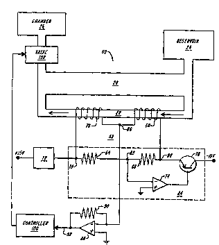
In ~igure 2 the plefcLlcd tr~n~dllcer 60 measures the mass flow rate of gas
16 flowing in sensor tube 22. Tran~ cer 60 includes a balanced bridge 58 of four
17 resistive elements, 64, 66, 68 and 70. Resistors 64 and 66 are standard resistors and
18 are chosen so that they are subst~nti~lly matched, i.e., such that R64 (the resistance
19 of resistor 64) and R66 (the resi~t~nre of resistor 66) are equal and each has
subst~nfi~lly the same thermal coefficient. Resistors 68 and 70 are preferably thermal
21 elements and are chosen so that they are m~t~h.ocl, i.e., have the same coefficient of
22 temperature so that for any given temperature, R68 (the resistance of thermal element
23 68) equals R70 (the resistance of thermal element 70). The thermal elements 68 and
24 70, however, do not n~cess~rily have to match the resistive elements 64 and 66. The
node 82 of the bridge between resistive elements 64 and 66 is connected to the
26 inverting input of an operational amplifier 74, the latter having its non-inverting
27 input conn~cte~ to system ground. The output of amplifier 74 is in turn connected
28 to the base of pnp transistor 76. The emitter of transistor 76 is connected to node 80
29 of the bridge (conn~cting the resistive element 66 to the thermal element 68), while
the collector of the transistor 76 is connected to a negative voltage source, e.g., -15
31 volts DC. The node 78 connecting the resistive element 64 to the thermal element
~ wo 96/00376 2 1 ~ ~3 ~ PCTIUS95l06328
70 is conn~-cted to a constant current source 72, the latter being powered by a
2 positive voltage source, e.g., + 15 volts DC. Finally, the node 86 is connected to the
3 inverting input of operational amplifier 88, the latter having its non-inverting input
4 connected to system ground and its output conn~cted through feedback resistor 90
to node 86. The output of amplifier 88 forms an output terminal 92 of the tr~n~ cer
6 60.
7 The constant current source 72 provides a current through resistive elements
8 68 and 70, and through resistors 64 and 66. Resistive elements 64 and 66, amplifier
9 74, and transistor 76 form a control system 84 that operates to m~int~in the voltages
at nodes 78 and 80 equal and opposite to one another so that the voltage at node 82
11 remains at virtual ground.
12 The tr~n~cln~er 60 operates in the following manner. With respect to the
13 control system 84, if the negative voltage at node 80, V80, decreases in m~gnih~
14 such that the voltage at node 78, V78, becomes greater in m~gnitllde than the negative
voltage V80, or V78 increases in m~gni~(le relative to V80 (i-e-, I V78 1 ~ I V80 1 )~
16 then the voltage at node 82, V82, will tend to drift above ground. When the voltage
17 V82 drifts above ground, the amplifier 74 provides a signal to the base of transistor
18 76 so that the latter becomes more conductive and thus draws more current so as to
19 pull V80 down forcing the voltage at node 82, V82, to virtual ground. If V80 increases
in m~gnit~lde such that the voltage V78 becomes smaller in m~gni1~lde than the
21 negative voltage V80, or V78 decreases in m~gnitllde relative to V78 (i.e., I V,8 1 <
22 I V80 1 ), then V82 will tend to'drift below ground. When V82 tends to drift below
23 ground, difference amplifier 74 adjusts transistor 76 to draw less current thereby
24 raising V80. When V82 is at exactly ground, difference amplifier 74 controls transistor
76 to continue drawing the same amount of current thereby m~int~ining V82 at the26 current level.
27 When no fluid is flowing through sensor tube 22, T68 (the temperature of
28 thermal element 68) equals T70 (the temperature of thermal element 70), and
29 therefore, R68 equals R70. Since the m~gni~llcle of V78 is m~int~inPd to equal to the
m~gnitllde of V80, the voltage across elements 68 and 70 will remain equal and
31 opposite to one another, with the node 86 (V86) rem~ining at virtual ground.
WO 96/00376 ;~ 1 ~88~ 2- PCT/US95/06328 ~
- 10 -
Fluid flowing through tube 22 cools thermal element 68 more than thermal
2 element 70 because element 68 is upstream of element 70. Therefore, fluid flowing
3 through tube 22 lowers R68 below R70 so as to cause the voltage at node 86, V86, to
4 tend to drift below ground. As V86 tends to drift below ground, dirrelelltial amplifier
88 supplies current to node 86 through feedback resistor 90 in order to m~int~in6 node 86 at virtual ground. The amount of current required to m~int~in V86 at ground
7 is representative of the mass flow of fluid flowing through tube 22. This current can
8 be measured by measuring the voltage across R;,o, or by directly measuring the
9 current at the non-inverting input of amplifier 88. Since this signal is a current at
ground level, it can be reliably measured remotely from the tr~nc~ er 60
11 components. Further, current through the bridge is supplied by constant current
12 source 72 so that the initial steady state temperatures (the temperatures at zero flow
13 after warm up), T68 and T70 essentially remain fL~ced above ambient temperature, but
14 are allowed to float with ambient temperature. Tr~ncclllcer 60, therefore, overcomes
the limitations of the two- and three-element constant temperature devices.
16 Figure 3 shows one modification to the embodiment of Figure 2. In this
17 embodiment, control system 84 inrlllcles a potentiometer 94 disposed between
18 resistors 64 and 66 for col,lpensating for any micm~trhf~s between the two resistors.
19 Potentiometer 94 thus facilitates balancing the voltages at nodes 78 and 80.
Figure 4 shows a comparison of the errors in the outputs of a tr~ncclllrer
21 constructed according to the invention (CURVE A) and the prior art tr~n.c~ cer
22 (CURVE B) illustrated in Figu~e 1. Figure 4 shows the relationship of error (as a
23 percentage of full scale) and the flow rate (as a percentage of full scale). As Figure
24 4 shows, the tr~ncd~lcer 60 constructed in accordance with the present invention
provides reduced error and an output response that is more linear than the prior art
26 tr~ncdllcer of the type shown in Figure 1.
27 The invention has been ~iiccllcc-ed in connection with balancing voltages V78
28 and V80 such that V78 equals -V80. As those skilled in the art will appreciate, rather
29 than tying the bridge circuit between +15 Volt and -15 Volt rails, the circuit could
be tied between, for example, + 10 Volt and ground rails. In this case, the sensor
31 would m~int~in V8~ and V86 at a system reference level of +5 Volts rather than at
~ w096/00376 2 1 6 ~ 0 32 PCT/USg5/06328
virtual ground. The sensor would still operate in the same fashion, and V78 and V80
2 would still be bal~nred at an iclentiral amount above and below, respectively, the
3 system reference level.
4 The tr~n.c~ cer 60 is particularly useful when used in combination with other
components so as to control the mass flow rate through the tube 22. For example,6 as shown in Figure 5, the output of the tr~nc~ cer 60 is shown connected to the
7 input of a mass flow controller 100. The output of the controller 100 is used for
8 controlling a proportional control valve 102, the latter for controlling the rate of flow
9 of gas from reservoir 24 to chamber 26. Controller 100 can be coupled to the output
of amplifier 88, as shown in Figure 5, in which case controller 100 measures the11 voltage across resistor 90 as the output signal; or controller 100 can be coupled to
12 the input of amplifier 88 in which case controller 100 measures the current at ground
13 as the output signal. As is well known, the proportional control valve can be
14 conn~ct~l upstream of tr~nC~ cer 60, or as shown, dowl~Ll~alll of the tr~nc~ cer.
The tr~nC~ cer 60 thus provides an improved mass flow trAncdllcer for
16 sensing the mass flow rate of a fluid through a channel. Mass flow tr~ncdll~er 60 is
17 believed to be more accurate because it operates in a more linear fashion than prior
18 art traditional two element, constant current, differential voltage type of mass flow
19 tr~ncdllcer, such as the type shown in Figure 1. P~eca -ce the output signal at the
input of amplifier 88 is a current relative to ground level, the output can be reliably
21 measured remotely from the tr~n.c~ cer, provide a stable zero indication, and be less
22 susceptible to noise. The mass flow tran.C~ cer 60 can be used reliably in conjunction
23 with a sensor tube and a by-pass tube for measuring the total mass flow through both
24 tubes as shown in Figure 5. The device operates reliably over a wide dynamic range
with thermal elements operating at a lell~ ture that floats at a specified value26 above the environment so as to increase the environmental temperature range and
27 reduce the effects of irregularities between the sensor channel and by-pass channel.
28 Finally, an improved mass flow control system comprising the mass flow tran.c-ll-c er
29 60 can provide more accurate control.
W 0 96/00376 2 ~ PCTrUS9~/06328
Since certain changes may be made in the above apparatus without departing
2 from the scope of the invention herein involved, it is intended that all matter
3 contained in the above description or shown in the acco~ allyhlg drawing shall be
4 illLel~ el~d in an illustrative and not a limiting sense.