Note: Descriptions are shown in the official language in which they were submitted.
2 ~ 6$053
10
TITLE: PACKER INFLATION SYSTEM
INVENTOR: MARTIN PAUL CORONADO
FIELD OF THE INVENTiUIV
The field of this invention relates to packers, particularly external casing
packers, and techniques and devices for inflating them, particularly when in
use
with slotted casing or liners.
IjAIlChKUUIVL VT l n~ tm v Lmuvm
In the past, typical completions would involve a casing which is run in the
wellbore and cemented. The wellbore thereafter is extended and a casing or
liner
is suspended to the uphole casing which had earlier been cemented. Typically,
1'mer hangers were used to suspend the lowermost portion of the casing or
liner
which is added, generally in a deviated wellbore. These lower casings
typically
involve the use of openings or slots extending into the horizontal segment of
the
wellbore. Typically, the slotted casing or liner was run with external
packers;
hence, the term ECP (external casing packer). In view of the openings or slots
in
the liner supporting the ECPs, internal mud or cement pressure could not be
used
within such liners to inflate the ECPs disposed along the length of the liner.
Instead, each ECP had to be isolated so that it could then be actuated to
expand
into contact with the wellbore, isolating the desired zones of slotted casing.
Prior
designs have been developed to isolate each specific ECP and allow it to be
inflated with mud or cement. Such prior designs are illustrated in U.S. patent
5,082,062. This patent, entitled "Horizontal Inflatable Tool," refers to a
tool
manufactured by CTC Corporation of Houston, Texas. This tool involved a
concept of isolation of an ECP, using an inner workstring, followed by a
series of
1
2168053
r
mechanical operations to begin the inflating operation. The problem with prior
design tools is that in deviated wellbores, it is difficult to communicate
mechanical
movement from the surface and know that, reliably, such movement has been
translated to an equal amount or degree of movement at the desired location.
Hence, the prior systems added a degree of unreliability to the inflation
procedure
for the ECPs, thus creating uncertainty as to whether each of the ECPs, as
desired,
had been fully inflated.
The apparatus and method of the present invention provide greater reliability
in knowing that the ECP has been properly inflated. Reliability is further
enhanced
by the hydraulic rather than mechanical operation. Reliability is built into
the sys-
tem through a variety of features which ensure, through pressure-equalizing
tech-
niques, the longevity of the seals around the opening for each ECP.
Additionally,
aprovision has been made to allow removal of any excess cement by a reversing
procedure. Finally, to minimize the effort required to remove the inflating
tool out
of the hole, other relief provisions have been incorporated into the design to
facilitate pulling out of the hole.
An inflation tool for an external casing packer (ECP) is provided. It allows
isolation of each ECP and inflation with mud, cement, or other fluids. The
opening
for the ECP is isolated by appropriate seals, while a passage in the inflation
tool
is closed off by a plug which allows internal.fluid pressure build-up. A
sliding
sleeve valve is responsive to built-up pressure and opens to allow access to
the
ECP. Upon complete inflation of the ECP, the pressure applied is removed,
allow-
ing the sleeve to close and the pressure between the seals surrounding the
opening
to the ECP is equalized with the wellbore. Excess mud or other inflation
material
2
CA 02168053 2005-04-22
can be reversed out by a bypass feature around the plug. A pressure-relief
feature in the inflation tool allows further pressure equalization for the
string,
which was used to run the tool in the hole, to facilitate its removal.
Accordingly, in one aspect of the present invention there is provided a
tool for inflation of one or more packers in a wellbore, having an opening
into
the packer for inflation thereof, comprising:
a body;
a seal assembly on said body to span an annular space between said body
and the packer and seal it off around the opening into the packer;
said body formed having a passage in communication with said annular
space whereupon application of pressure to said passage, said packer is
inflated
as said seal assembly retains the applied pressure in said annular space and
facilitates its communication into the opening of the packer for fluid
inflation
thereof;
said body further comprises a valve member mounted to said body and
movable between an open and closed position responsive to applied pressure in
said passage to selectively allow pressurization of said annular space form
said
body.
According to another aspect of the present invention there is provided a
method of inflating at least one external packer mounted on a casing or liner,
comprising:
positioning an inflating tool adjacent an opening leading into the packer;
isolating the opening with a sealing system that straddles the opening;
applying fluid pressure to operate a valve to inflate the packer.
According to yet another aspect of the present invention there is provided
a pressure-actuated downhole tool positioned on a string or coiled tubing from
the surface and into a wellbore, said string or coiled tubing defining an
annulus
in the wellbore, comprising:
3
CA 02168053 2005-04-22
an elongated body having a passage therethrough and an upper end
connected to the tubing or string;
a plug for selectively obstructing said passage when dropped into said
body through said tubing or string, whereupon said tool can be actuated by
internal pressure build-up from the surface;
a bypass passage in said body around said plug in said passage, further
comprising a one-way valve mounted therein, said one-way valve facilitating
pressure build-up in said body from the surface against said plug and said one-
way valve and permitting reverse flow from the annulus down around said
tubing or string, and into said passage under said plug and passing through
said
one-way valve and to the surface through said tubing or string.
According to still yet another aspect of the present invention there is
provided a pressure-actuated external packer inflating tool, adapted to be run
into a wellbore from the surface on tubing or a tubing string, comprising:
a body externally sealingly positionable adjacent the packer;
a plug selectively insertable into said body to obstruct a passage therein,
said body having a port above said plug when said plug is inserted into said
body, said port in fluid communication with the packer when the tool is
sealingly positioned adjacent thereto, said plug facilitating internal
pressure
build-up from the surface to inflate the packer;
a bypass passage in said body extending, on both ends, into said passage
in said body and around said plug and further comprising a one-way valve
therein;
whereupon pressure build-up from the surface is possible against said
one-way valve and said plug, and reverse flow into said passage of said body
form below said plug bypasses around said plug for facilitating removal of
inflating material from said body.
3a
CA 02168053 2005-04-22
BRIEF DESCRIPTION OF THE DRAWINGS
Embodiments of the present invention will now be described more fully
with reference to the accompanying drawings in which:
Figure 1 illustrates the use of a slotted liner in combination with ECPs.
Figures 2A to 2E show a sectional elevational view of the inflation tool
in the run-in position.
Figures 3A to 3E show the view of Figure 2, showing the tool properly
positioned inside an ECP opening prior to inflation.
Figures 4A to 4E show the view of Figure 2, shown after landing the
plug and applying fluid pressure to inflate the ECP.
Figures SA to SE illustrates the movement of the tool from one ECP to
another after inflation of the first ECP.
Figures 6A to 6E illustrates the reversing out procedure after inflation of
all ECPs,
Figures 7A to 7E illustrates the procedure for pressure equalization in
the running string to facilitate the removal of the tool after inflation of
all ECPs
and reversing out.
Figure 8 is a schematic of the internal valuing of a typical ECP.
DETAILED DESCRIPTION OF THE PREFERRED EMBODIMENT
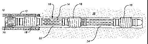
Figure 1 illustrates the typical situation involving the use of the
apparatus A of the present invention. Initially, a wellbore 14 is drilled and
a
liner 10 is secured in position with cement 12. Thereafter, the wellbore 14 is
further extended beyond the end of liner 10. Typically, in horizontal
completions, a slotted liner 16 is run into the wellbore 14 with a plurality
of
external casing packers or ECPs 18.
3b
CA 02168053 2005-04-22
t
The slotted liner assembly 16 is typically secured to liner 10 with liner
hanger 20,
a device well-known in the art. Those skilled in the art will readily
appreciate that
the annular spaces 22 and 24 in this type of an operation are in communication
with the formation 26, thereby precluding the use of applied pressure within
the
slotted liner 16 to inflate the ECPs 18. Pressure applied within the interior
of the
slotted liner 16 will communicate undesirable pressure applied to the
formation 26.
Accordingly, it is desirable to isolate each ECP 18 for selected inflation.
The
apparatus and method illustrated in Figures 2-7 illustrates how to accomplish
selective filling of the ECPs 18 using fluid pressure.
Referring now to Figure 2, the apparatus A of the present invention is illus-
trated in the position of running in the hole to the first ECP 18. The
apparatus A
has a top sub 28 which has a thread 30 to which a string or coiled tubing can
be
rpnnected to allow running the apparatus A into the desired depth from the
surface.
An outer top sleeve 32 is connected by tread 34 to top sub 28. Sleeve 32 works
in conjunction with sleeve 36 (see Figure 2d) to retain an assembly of seals
as will
be described below. Located internally of outer top sub 32 and outer bottom
sub
36 is a tubular passage 38, which is defined by a series of attached tubular
mem-
bers 40-50. It can be seen that tubular member 40 is sealingly engaged to top
outer sleeve 32 by virtue of seal 52, while at the other end of passage 38,
seal 54
provides the seal between tube 50 and Quter bottom sub 36.
A lateral port 56 extends radially from passageway 38 into variable-volume
cavity 58. Seals 60 and 62 seal off variable-volume cavity 58 such that upon
pressure build-up therein, movement of piston 64 occurs, as seen by comparing
Figures 3 a~ 4.
A bypass flow passage 68 exists throughout the tool and begins at lateral
port 66. The bypass or equalizing passage 68 is marked throughout Figure 2. At
4
21b8a53
its lower end as shown in Figure 2d, a lateral port 70 allows the bypass
passage 68
to emerge downhole from the sealing assemblies which will be later described.
Returning now to piston 64, it can be seen. that the piston 64 is biased by
a stack of Belleville washers 72 into the closed position as shown in Figure
2.
While Belleville washers are illustrated as the biasing mechanism, other mecha-
nisms, such as springs, pressure imbalances due to piston configurations, can
also
be used to bias the piston 64 into the position shown in Figure 2 without
departing
from the spirit of the invention. The washers 72 are located in a compartment
74
which is open to the bypass passage 68 through one or more lateral openings
76.
Thus, when the washers 72 are compressed as shown in Figure 4, the reduced
volume of compartment 74 results in fluid displacement through lateral
passages
76 and into the bypass passage 68. Those skilled in the art will appreciate
that the
fluid displacement feature of passages 76 allow the washers 72 to compress
when
subjected to movement of piston 64 due to pressure build-up in cavity 58.
As shown in Figure 2b, the piston 64 has a bypass passage 78 which com-
municates through passage 80 into bypass passage 68 in the position shown in
Figure 2. Seals 60 and 81 sealingly isolate passage 78 to channel it into
passage
80 and ultimately into the bypass passage 68 during the run-in position. A
seal
82 is also mounted to piston 64 for ultimate isolation of passage 80 from
passage
78, as will be described below.
The sealing assembly comprises upper cup seals 84 and 86, which are re-
tained in a conventional manner. It is to be noted that while cup seals 84 and
86
are illustrated in the preferred embodiment that other types of seals can be
used
without departing from the spirit of the invention. Oriented in a
reversemanner
and mounted closer to outer bottom sub 36 are seals 88 and 90, which in the
pre-
ferred embodiment are identical to seals 84 and 86. Again, seals 88 and 90 are
5
2168453
retained in the customary manner known in the art. Seals 86 and 88 define
annular
spaces 92 and 94 between the apparatus A and the ECP body 96 (see Figure 3b).
Annular spaces 92 and 94 are separated by a wiper 98. Wiper 98 helps to reduce
the size of annular space 92 which will fill up with cement or other fluid
during
the inflation procedure.
Seals 84-90 and wiper 98 are preferably made of nitrite rubber 90 Durome-
ter. As shown in Figure 2d, passage 38 has a plurality of teeth 102, or other
devices known in the art, for ultimately catching and retaining a wiper plug
104
(see Figure 4d). When a wiper plug 104 is engaged sealingly in passage 38 to
teeth 102, pressure can be built up in passage 38. A lateral port 106 (see
Figure
2d) extends into a bypass passage 108. Passage 108 reconnects to passage 38 at
lateral port 110. A plurality of balls 112, biased by springs 114 against
seats 116,
allow the pressure in passage 38 to be retained by not letting it escape
through
bypass passage 108 due to ball 112 being seated against seat 116. However,
when
the pressure is applied in the opposite direction into passage 108 after the
wiper
plug 104 is sealingly blocking passage 38, reverse flow is possible due to
compres-
sion of spring 114, as shown in Figure 6d. This procedure will be explained
below.
A locating mechanism 118 is connected to the apparatus A as shown in
Figure 2e. As shown in Figure 3e, the locating mechanism 118 catches a recess
120 in the wall 100 of ECP body 96 or in the liner immediately adjacent
thereto
in order to properly locate seals 86 and 88 straddling opening 122 in the ECP
wall
100 (see Figure 3b).
The ECP 96 has an inflatable element 124 which, upon application of pres-
sure through opening 122, results in an inflated element as shown in Figures 1
and
4. Referring now to Figure 8, a schematic illustration of a possible internal
ECP
6
2168053
t
configuration is illustrated. In one potential application, a knock-off plug
126 can
be supplied which is in some applications knocked off by a wiper plug such as
plug 104. In the preferred design, a knock-out plug 126 is not employed;
instead,
piston 64 effectively covers variable-volume cavity 58 until predetermined
pressure
S conditions are met. This, in turn, shifts piston 64 from the position shown
in
Figure 3 to the position shown in Figure 4. As shown in Figure 4b, seals 62
have
come away from surface 128, exposing a clear flowpath from cavity 58 through
annular space 92 and into opening 122, which, in turn, communicates with the
inlet
to the ECP shown schematically as 130 in Figure 8. Internally, the ECP has a
passageway 132 leading into the inlet 134 of delay open valve 136. Delay open
valve 136 is nothing more than a piston 138 which initially blocks passage 140
from passage 132. Once sufficient pressure is built-up in passage 132, a shear
pin
X42, which may be a pin or a wire, breaks, allowing the piston 138 to shift to
align
passages 132 and 140. At that time, the flow is directed to a piston 144 in
check
valve 146. ~ The spring 148 is compressed, allowing passage 140 to align
itself with
passage 150. Passage 150 is connected to the inflate limit valve 152. Inflate
limit
valve 152 has pistons 154 and 156 which, in the initial position, are secured
by a
shear wire 158 and align the passage 150 to the element 124 through passage
160.
Eventually, the element 124 inflates and pressure begins to build in return
passage
162, which comes back from the element 124. Since piston 156 has a greater
surface area exposed to passage 162 than the surface area exposed to the
annular
space between pistons 154 and 156 around connecting rod 164, the assembly of
pistons 154 and 156 translates toward the shear wire 158. The translational
move-
ment of pistons 154 and 156, of course, shears the shear wire 158. Eventually,
piston 156, which has seals 166 and 168, winds up in the position where seals
166
and 168 straddle passage 150 to prevent any further pressure transmission from
7
~ j ~sa~3
s
passage 150 into passage 160. In this manner, the inflate limit valve 152
keeps the
element 124 from overinflating. This can be particularly important if, for any
reason, there has been a washout of the formation ?,6 adjacent to where the
element
124 is inflating. The valve 152 ensures that the element 124 is not
overpressured
in that situation as well as in others.
As seen in Figures 2-7a, the top sub 28 has a lateral passage 170, which is
initially obstructed by a rupture disc 172. This disc 172 is ruptured in the
proce-
dure shown in Figure 7 to facilitate equalization of pressure within passage
38,
internally of the apparatus A, to the annular space 173, outside the apparatus
A, to
facilitate removal of the tubing string or coiled tubing from the wellbore
without
having to lift the weight of the liquid or fluid in the running string or
coiled tubing
down to top sub 28. In the event for any reason the rupture disc 172 fails to
rupture on pressure build-up due to a failure of a seal in the area of wiper
plug
104 or ball 112 on seat 116, or cup seals 84-90, as shown, respectively, in
Figures
4d, then a~ ball 180 can be dropped onto a seat 174 to obstruct the passage 38
to
allow subsequent pressurization from the surface to break rupture disc 172.
All the principal parts of the apparatus A now having been described, its
operation will now be reviewed in detail. The apparatus A is lowered into the
existing casing or liner 10, as shown in Figure 1, in conjunction with a liner
hanger
20, or it may be separately inserted afterward. The apparatus A may be part of
the
assembly that is already suspended to the liner hanger 20 such that when the
liner
hanger 20 is actuated into attachment to the cemented liner 10, the apparatus
A can
then be regrabbed or properly positioned for inflation of the ECPs 18. Alterna-
tively, the slotted casing or liner 16, with a liner hanger 20, can be
separately run
into the cemented casing or liner 10 and secured thereto. 'Thereafter, in a
separate
trip into the wellbore, the apparatus A can be inserted through the liner
hanger 20
8
21b8Q53
s
and properly positioned for ECP inflation. In the preferred embodiment, the
lowermost ECP 18 in the wellbore is inflated first. However, the apparatus A
is
capable of inflating the ECPs 18 in a different order without departing from
the
spirit of the invention.
As shown in Figure 2, the apparatus A is run through the slotted liner 16
until, as indicated in Figure 3e, the locating mechanism 118 comes into
alignment
with a groove 120. At that point, the driller can pick up at the surface and
en-
counter some resistance to know that the engagement reflected in Figure 3e has
occurred. When this occurs, the apparatus A is positioned in the manner
illustrated
in Figure 3b, with lateral opening 122 positioned between seals 86 and 88. In
essence, opening 122 to the ECP 18 which has the inflatable element 124 has
now
been placed in the position shown in Figure 3d. At this point, piston 64 still
effec-
tively covers the annular passage 92 in view of seal 62 still being engaged to
surface 128. However, as the wiper plug 104 is landed and securely engaged on
teeth or gripping device 102 (see Figure 4d), pressure may begin to be built
up in
passageway 38, which communicates through passageway 56 to create a force
downwardly on piston 64 against the force of the stack of Belleville washers
72.
Eventually, there is a force imbalance on piston 64, causing it to shift to
compress
the Belleville washers 72. As the piston 64 shifts, seal 82 moves beyond
passage
80, effectively isolating passage 78 from bypass passage 68 (see Figure 4b).
Accordingly, when piston 64 shifts, passage 56 becomes aligned with passage
122
into the ECP 18 to inflate the element 124. At the same time, to allow
pressure
to be transmitted through passage 122 via annular space 92, the passage 78,
which
had previously communicated with the bypass passage 68, is in fact isolated
therefrom by the positioning of seal 82 between passage 78 and passage 80.
Pres-
sure thus builds in annular space 92, which gay be fully captured by wiper 98
in
9
2168Q53
r
the ideal situation, and if not, seals 88 and 90 help contain any developed
pressure
which gets beyond wiper 98 within annular space 94. As previously stated, any
built-up pressure in passage 38 cannot get around wiper plug 104 because of
ball
112 seating on seat 116. Once the maximum inflation pressure is applied to
element 124, the driller or other operators at the surface will detect that
this condi-
tion has occurred, at which point the pressure of preferably cement used to
inflate
the element 124 will be removed. At this time, piston 64 is biased by
Belleville
washers 72 to resume the run-in position shown in Figure 2b, thus closing off
passage 56 to annular passage 92 with seal 62. Again, it should be noted that
other
fluids or materials can be used to inflate the element 124 without departing
from
the spirit of the invention.
Comparing Figure 5 to Figure 4, the apparatus A is raised to the next ECP
.18. It should be noted that at the time the apparatus A is moved to position
itself
next to an adjacent ECP 18 that passage 78 has once again achieved fluid commu-
nication with the bypass passage 68 through opening 80. The Belleville washers
72, which had expelled fluid from compartment 74 through opening 76, again
accept more fluid from the bypass passage 68 as they resume their initial
position
shown in Figure 2. Thereafter, the apparatus A is positioned once again
straddling
an opening such as 122 on another 18 and the process is repeated as previously
described. At the time of movement of the apparatus A, passages 92 and 94 are
equalized with passage 68 so that there is no differential pressure across
seals 84,
86, 88, and 90.
Having successfully inflated all the ECPs 18, it is then desirable to reverse
flush any excess cement or other inflating material from inside the passageway
38.
In order to accomplish this, drilling mud is pumped from the surface on the
outside
of the apparatus A in annular space 173. The mud enters passage 66 and
proceeds
2t68053
t
down the bypass passage 68 to emerge at passage 70 (see Figure 6). Having
emerged from passage 70 into annular space 176 around seals 84-90, the mud
flow
can go around the bottom of the apparatus A and back into passage 38 (see
Figure
6e). The mud now flows uphole in passage 38 until it comes to lateral port
178.
There may be one or more ports 178, all of which are situated below wiper plug
104. The mud flow provides an upward pressure on ball 112 which moves the ball
to compress the spring 114, thereby unseating ball 112 from seat 116. The mud
continues to flow around ball 112 into port 106 and back into passageway 38
around wiper plug 104. Thereafter, the mud can flow uphole through the coiled
or rigid tubing connected to the top sub 28 and out to the surface. ,In that
manner,
the internals of the apparatus A, particularly the passage 38, can be
effectively
reversed to remove any excess inflating material. It should be noted that
during
the inflating procedure illustrated in Figure 4, very little inflating
material winds
up entering the annular space 92. At this time, the equalizing line 78 remains
closed off because of seal 82 to the bypass passage 68. After pressure in
passage
38 is released, the excess pressure in annular space 92 over the well pressure
seen
in bypass passage 68 results in a net outflow from annular passage 92, thus
expel-
ling any cementitious material or other material used to inflate element 124
from
annular passage 92. Similarly, once piston 64 closes after the inflation of
element
124, as shown in Figure S, the cementitious or other material used to inflate
the
element 124 is only principally disposed in passage 56 and variable-volume
cavity
58. The reversing out procedure, as illustrated above and shown in Figure 6,
effectively removes any accumulated material from these areas.
The final step is to remove the tubing string or coiled tubing from the
wellbore, which is attached to the apparatus A at top sub 28. Since passage 38
is
sealed off with plug 104, any attempt to bring up the coiled tubing or rigid
tubing
11
216$053
up at the surface would necessarily result in lifting up the weight of the
fluid
within the coiled or rigid tubing connected to top sub 28, as well as
internally in
passage 38 of the apparatus A. To allow equalization between the rigid or
coiled
tubing connected to top sub 28 and the annular space 173, a rupture disc 172
is
S employed to allow fluid communication from passage 38 into annular space 173
once it breaks. The driller or other surface operators simply increase the
pressure
in passage 38 which is sealed off by wiper plug 104. As the internal pressure
builds up, ball 112 is held rigidly against seat 116 by spring 114. The
resulting
pressure build-up ultimately breaks rupture disc 172. If for any reason there
is a
leak or pressure fails to build up in passageway 38 to allow the rupture disc
172
to break, a ball seat 174 is provided in top sub 28 (see Figure 7). A ball 180
can
be dropped from the surface to sealingly land against seat 174 to obstruct
passage
~8 within top sub 28. Once that occurs, pressure is again built up from the
surface
until rupture disc 172 breaks. It should be noted that the ball-dropping
procxdure
illustrated above is a secondary or backup pressure to the main way for
breaking
rupture disc 172, which comprises simply pressuring up against wiper plug 104.
Once the rupture disc 172 is broken, the head of liquid or fluid within the
rigid or
coiled tubing above top sub 28 equalizes with the annular pressure in annular
space
173 such that lifting of the apparatus A out of the wellbore does not entail
the
actual lifting of the fluid within the rigid or coiled tubing attached to the
apparatus
A.
Those skilled in the art will appreciate that the apparatus A and the tech-
piques involved using the apparatus A give a reliable way to inflate ECPs in a
nonmechanical manner. What is illustrated here is a reliable technique to
provide
assurance that each ECP 18 is properly inflated. Pressure across the cup seals
is
also equalized prior to movement of the apparatus A. The bypass feature around
12
21b8053
the wiper plug 104 facilitates reversing out so as to allow any excess
inflating
material, such as perhaps a cementitious material, to be reversed out to the
surface
through the rigid tubing or coiled tubing used to suspend the apparatus A. An
equalizing feature is provided to eliminate the need to pick up the weight of
liquid
within the coiled or rigid tubing supporting the apparatus A by allowing
equaliza-
tion through the rupture disc 172. By allowing the annular space 92 to be
vented
to a bypass line and pressure equalized, again the useful life of the seals,
particu-
larly 88 and 90, is increased because the annular space 92 and 94 which they
define in effect becomes equalized through passageway 68, with the surrounding
pressure in annulus 173 before the apparatus A is moved along the wall 100.
Particularly in deviated wellbores, the actuation system offers a far more
reliable
technique than mechanical actuations which can result in uncertainties as to
wheth-
~er the required downhole movement has been effectively transmitted from the
surface. By making the inflation procedure of the ECP controlled by hydraulics
or fluid action, the uncertainties of mechanical actuation have been
eliminated. The
design featuring fluid or hydraulic actuation is a more compact design, which
can
be easily tailored to a variety of situations. The stack of washers 72, for
example,
can be changed to accommodate the expected forces to be encountered in a
partic-
ular application so as to keep the piston 64 in its initial or run-in position
at the
depths encountered and for the fluid conditions expected.
The foregoing disclosure and description of the invention are illustrative and
explanatory thereof, and various changes in the size, shape and materials, as
well
as in the details of the illustrated construction, may be made without
departing
from the spirit of the invention.
uata~patears~3ooW..pp as
13