Note: Descriptions are shown in the official language in which they were submitted.
2168292
PNEUMATIC TIRE HAVING A SINGLE CARCASS PLY
REINFORCED WITH METALLIC CORDS,
A HIGH ENDING PLY, TURNUP AND LOCKED BEAD CONSTRUCTION
Background of the Invention
The present invention relates to a pneumatic tire
having a single carcass reinforced with high strength
metallic cords and a high ending turnup and a locked
bead construction.
Technical Field
The desirability of having the turnup portions of
the carcass ply (or plies) of a pneumatic tire extend
radially outwardly of the bead core the shortest
possible distance is the premise on which prior art
locked beads were developed. The proposed advantages
included improved bead durability, and reduced
material costs.
U. S. Patent 4,922,985, issued May 8, 1990,
discloses a carcass ply 30 having a main portion that
extends between both bead cores (not shown) of the
tire and turnup portions that are anchored around each
bead core 31. Tires according to U.S. Patent
4,922,985 have the radially outer edges of the turnup
portions of the carcass ply disposed radially
outwardly of the bead cores a m;n;m~l distance and are
in contact with the main portion of the carcass ply.
Suitable elastomeric materials surround the bead core,
carcass ply and other elastomeric components to
complete the bead portion of the tire. In Figure 4 of
this patent, there is illustrated a clamping member
432 comprised a strip of side-by-side cords of a heat
shrinkable material embedded in a suitable elastomeric
substance having a permanent thermal shrinkage of at
least 2 percent. This strip of cords extended from a
2168292
-
-- 2
location radially and axially inward of the bead core
431 to a location radially outward of the bead core
and there was no filler strip or apex disposed between
the main portion and turnup portion of the carcass
ply.
Tires according to U.S. Patent 4,922,985 were
manufactured using a clamping member in which the heat
shrinkable material was 1260/2 Nylon 6,6, having a
permanent thermal shrinkage of about 4 percent. It is
continually the goal in the art to simplify the
construction and reduce the expense of building tires,
yet improve the durability, handling, rolling
resistance and other properties of tires.
Summary of the Invention
The present invention relates to a pneumatic tire
having a pair of axially spaced apart annular bead
cores and a single carcass ply which is folded about
each bead core. Each bead core comprises a plurality
of wraps of a single metallic filament. The single
carcass ply is reinforced with parallel metallic cords
composed of at least one filament having a tensile
strength of at least (-2000 x D + 4400 MPa) x 95~,
where D is the filament diameter in millimeters. The
single carcass ply is folded about each bead core.
The single carcass ply has a main portion that extends
between the bead cores and turnup portions that are
folded around the bead cores. A radially outer edge
of each turnup portion is in contact with the main
portion of the carcass ply and extends to an end point
0.5 inches (12.7 mm) to 4.0 inches (101.6 mm) radially
outward of the bead core, as measured along the main
portion of the carcass ply of the tire. No bead apex
or filler is present between the carcass turnup and
the main portion of the carcass ply. A toe guard
216829~
-
-- 3
associated with each bead has each end (first and
second) of the toe guard being disposed directly
adjacent to the carcass ply. One (the first) end is
located on the axially inner side of the main portion
of the carcass ply at a location about .4 to 3.5
inch(s) (10 mm to 89 mm) radially outward of the bead
core as measured along the main portion of the carcass
ply. The other or second end of the toe guard is
located at a point ranging from substantially the
axially outermost point of the bead core to a location
about 3.5 inches (89 mm) radially outward of the bead
core as measured along the turnup portion of the
carcass ply. The first end and second end of the toe
guard is a shorter radial distance from said bead core
than the end point of the turnup radial portion of the
carcass ply. The respective turnup portion of the
carcass ply is directly adjacent to both the toe guard
and the bead core.
Brief Description of the Drawings
Figure 1 is a partial or fragmentary
cross-sectional view of a tire according to the
present invention; and
Figure 2 is a fragmentary cross-sectional view of
the bead portion of a tire according to the present
invention mounted upon a rim.
Detailed Description of the Invention
As used herein and in the claims:
"Axial" and "axially" are used herein to refer to
lines or directions that are parallel to the axis of
rotation of the tire.
"Bead" means that part of the tire comprising an
annular tensile member wrapped by ply cords and
shaped, with our without other reinforcement elements
216829~
-- 4
such as flippers, chippers, apexes, toe guards and
chafers, to fit the design of the tire rim.
"Belt structure" means at least two layers of
plies of parallel cords, woven or unwoven, underlying
the tread, unanchored to the bead, and having both
left and right cord angles in the range from about 17
to about 27 degrees with respect to the equatorial
plane (EP) of the tire.
"Carcass" means the tire structure apart from the
belt structure, the tread and the undertread, but
including the beads. The carcass ply includes
reinforcing cords embedded in an elastomeric substance
and that these components are considered to be a
single entity. The "main portion of the carcass ply"
means the portion of the carcass ply which extends
between the bead cores.
"Cord" means one or more of the reinforcement
elements, formed by one or more filaments/wires which
may or may not be twisted or otherwise formed and
which may further include strands that may or may not
be also so formed.
"Crown" means that portion of the tire within the
width limits of the tire tread.
~ Equatorial plane (EP)" means the plane
perpendicular to the tire's axis of rotation and
passing through the center of the tire's tread.
"Load Range" means load and inflation limits for
a given tire used in a specific type of service as
defined by tables in The Tire and Rim Association,
Inc, 1995 Year Book.
"Ply" means a continuous layer of rubber-coated
parallel filaments.
I'Pneumatic tire" means a laminated mechanical
device of generally toroidal shape (usually an open-
torous) having beads, a carcass ply and a tread.
21682!3~
- 5
"Prefix Letters" means those identifications used
and defined in The Tire and Rim Association, Inc, 1995
Year Book.
~ 'Radial~ and "radially" are used to mean
directions radially perpendicular from the axis of
rotation through the tire.
"Radial-ply tire" means a belted or
circumferentially restricted pneumatic tire in which
the carcass ply reinforcements which extend from bead
to bead are laid at angles between 75 and 105 with
respect to the equatorial plane of the tire.
"Rivet" means the open space between cords in a
layer.
~ Section width~ means the maximum linear distance
parallel to the axis of the tire and between the
exterior of its sidewalls when and after it has been
inflated at normal pressure for 24 hours, but
unloaded, excluding elevations of the sidewalls due to
labeling, decoration or protective bands.
~Tensile strength" is determined by ASTM A370-92
as applied to steel wire product.
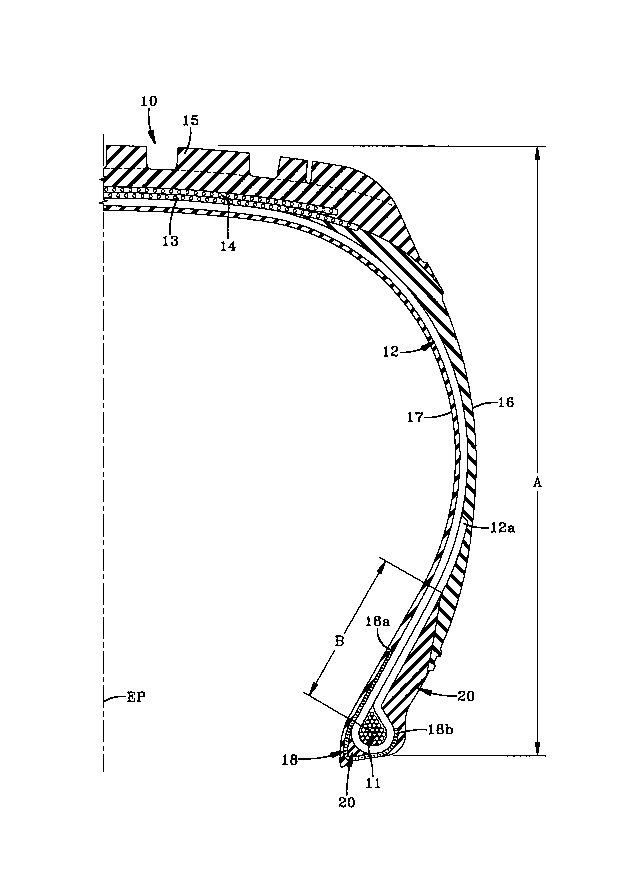
Referring now to Figures 1 and 2, there is shown
a fragmentary cross-sectional view of a tire 10
according to the present invention and an enlarged
fragmentary view of a bead portion and lower sidewall
mounted upon a rim.
Figure 1 shows a fragmentary cross-sectional view
of a tire 10 of the present invention. The tire has a
pair of bead cores 11 (only one shown) which each
comprise a plurality of metallic filaments. The tire
10 is characterized by a single carcass ply 12 that
extends between the bead cores 11 and a turnup portion
anchored around each bead core 11. A belt structure
having at least two belts 13,14 is disposed radially
outwardly of the main portion of the carcass ply and a
2168292
-
- 6
ground engaging tread portion 15 is disposed radially
outwardly of the belt structure. Sidewall portions 16
(one shown) extend radially inwardly from the tread
portion to the bead portions. On the axially inner
side of the carcass ply, an innerliner 17 may be used.
The innerliner consists of a layer or layers of
elastomer or other material that form the inside
surface of the tire and contains the inflating fluid,
such as air, within the tire 10. It may be desirable
to place additional barriers, reinforcement strips or
gum strips (not shown) at suitable locations between
the innerliner 17 and main portion of the carcass ply
to avoid penetration of rubber through the carcass ply
during curing.
One critical aspect of the invention is a single
ply carcass construction reinforced with parallel
metallic cords composed of the above-described
filaments. There are a number of metallurgical
embodiments which result in the tensile strength
defined above. One way of achieving such strength is
by merging the proper process and alloys as disclosed
in U.S. Patent 4,960,473 and 5,066,455, which are
hereby incorporated by reference in its entirety
herein, with a steel rod microalloyed with one or more
of the following elements: Ni, Fe, Cr, Nb, Si, Mo,
Mn, Cu, Co, V and B. The preferred chemistry is
listed below in weight percentages:
C 0.88 to 1.0
Mn 0.30 to 0.05
Si 0.10 to 0.3
Cr 0 to 0.4
V 0 to 0.1
Cu 0 to 0.5
Ni 0 to 0.5
Co 0 to 0.1
the balance being iron and residuals
2168292
-
-- 7
The resulting rod is then drawn to the appropriate
tensile strength.
For equal filament diameters, the cords used in
the present invention have higher strength and
generally higher fatigue life over prior art tensile
cords. These advantages lead to pneumatic tires which
have less reinforcement material and thus lower weight
and cost. Further the life of the tire can be
increased with the increase in fatigue life of the
cord and its filaments. When the new cord structures
incorporate filaments having a smaller diameter, there
is a resulting reduction in gauge material and cost as
compared with the high or super tensile strengths
making the tires lighter in weight and less costly.
The cords for use in the single ply carcass ply
may comprise from one (monofilament) to multiple
filaments. The number of total filaments in the cord
may range from 1 to 13. Preferably, the number of
filaments in per cord ranges from 6 to 7. The
individual diameter (D) of each filament generally
ranges from .15 to .30 mm for each filament having at
least a tensile strength of (-2000 x D + 4400) x 95
where D is the filament diameter in mm. Preferably,
the diameter of each filament ranges from .17 to .22
mm.
Another critical property of the steel cord is
that the total elongation for each filament in the
cord must be at least 2 percent over a gauge length of
25 centimeters. Total elongation is measured
according to ASTM A370-92. Preferably, the total
elongation of the cord ranges from about 2 percent to
4 percent. A particularly preferred total elongation
ranges from about 2.2 to about 3Ø
The torsion values for the steel for the filament
used in the cord should be at least 20 turns with a
2168292
- 8
gauge length of 200 times the diameter of the wire.
Generally, the torsion value ranges from about 20 to
about 100 turns. Preferably, the torsion values range
from about 30 to about 80 turns with a range of from
about 35 to 65 being particularly preferred. The
torsion values are determined according to ASTM Test
Method E 558-83 with test lengths of 200 times the
diameter of the wire.
There are a number of specific metallic cord
constructions for use in the single carcass ply.
Representative examples of specific cord constructions
include 1 x, 2 x, 3 x, 4 x, 5 x, 6 x, 7 x, 8 x, 11 x,
12 x, 1 + 2, 1 + 4, 1 + 5, 1 + 6, 1 + 7, 1 + 8, 2 + 1,
3 + 1, 5 + 1, 6 + 1, 11 + 1, 12 + 1, 2 + 7, 2 + 7 + 1,
3 + 9, 1 + 5 + 1 and 1 + 6 + 1 or 3 + 9 + 1, the outer
wrap filament may have a tensile strength of 2500 MPa
or greater based on a filament diameter of .15 mm.
The most preferred cord constructions including
filament diameters are 3 x .18, 1 + 5 x .18, 1 + 6 x
.18, 2 + 7 x .18, 2 + 7 x .18 x 1 x .15, 3 + 9 x .18 +
1 x .15, 3 + 9 x .18, 3 x .20 + 9 x .18 and 3 x .20 +
9 x .18 + 1 x 15. The above cord designations are
underst~n~hle to those skilled in the art. For
example, designation such as 2 x, 3 x and 4 x mean a
bunch of filaments; ie, two filaments, three
filaments, four filaments and the like. Designation
such as 1 + 2 and 1 + 4 indicate, for example, a
single filament wrapped by two or four filaments.
The carcass ply 12 has a layer of the above-
described steel cords arranged so as to have from
about 5 to about 70 ends per inch (~ 2 to 28 ends per
cm) when measured at the equatorial plane of the tire.
Preferably, the layer of cords are arranged so as to
have about 7 to about 20 ends per inch (~ 2.7 to 8
ends per cm) at the equatorial plane. The above
2168292
g
calculations for ends per inch are based upon the
range of diameters for the cord, strength of the cord
and the practical strength requirement for the carcass
ply. For example, the high number of ends per inch
would include the use of a lower diameter cord for a
given strength versus a lower number of ends per inch
for a higher diameter wire for the same strength. In
the alternative, if one elects to use a cord of a
given diameter, one may have to use more or less ends
per inch depending on the strength of the cord.
The metallic cords of the carcass ply 12 are
oriented such that the tire according to the present
invention is what is commonl y referred to as a radial.
The steel cord of the carcass ply intersect the
equatorial plane (EP) of the tire at an angle in the
range of from 75 to 105. Preferably, the steel
cords intersect at an angle of from 82 to 98. The
preferred range is from 89 to 91.
A tire according to the present invention has a
pair of axially spaced-apart bead cores 11 which each
comprise a plurality of wraps of a single metallic
filament. Each of the bead cores has a radial
cross-sectional shape which may be substantially
pentagonal, hexagonal, rectangular or circular. In
the instance where the bead has a radial cross-
sectional shape which is substantially pentagonal, the
greatest axial width of the bead core is located
radially outwardly of the radially innermost edge of
the bead core. As used herein, a "radial cross
section" is a cross section taken in a plane which
contains the axis of rotation of a tire or tire and
rim assembly. As used herein, "substantially
pentagonal" is understood to mean a five-sided cross
section, even though some or all of the sides may be
curvilinear rather than rectilinear, as in a regular
2168292
,
- 10 -
pentagon. The radially outermost extent of the bead
core being a vertex of two of the sides of the
pentagon and the greatest axial width of the bead core
being located radially outwardly of the radially
innermost edge of the bead core.
A carcass ply 12 and a toe guard 18 are folded
about each bead core 11. As mentioned above, the
carcass ply 12 has a main portion that extends between
the bead cores and turnup portions that are folded
around the bead cores 11. The radially outer edge of
each turnup portion is in contact with the main
portion of the carcass ply and extends to an end point
12a 0.5 inches (12.7 mm) to 4.0 inches (101.6 mm)
radially outward of the bead core 11, as measured
along the main portion of the carcass ply of the tire.
Preferably, the turnup portion extends to an end point
12a 0.5 inches (12.7 mm) to 3.5 inches (88.9 mm)
radially outward of the bead core 11. The locking in
of the bead is achieved by the adhesion between the
high turnup and the main portion of the single carcass
ply, and the restriction of the flange of rim 22 when
the tire is mounted on the rim and inflated. As can
be seen in Figure 2, the entire bead construction is
below the top of the flange, and the pentagonal shape
of the bead compliments the natural pressures between
the tire and the rim in holding the bead on the rim
when the tire is inflated. This is particularly true
when tires employing high inflation, e.g. 50 psi, use
the construction of the present invention. Also,
because the axially outer end of the toe guard 18 is
clamped below the top of the rim flange 22a, chances
that the toe guard would suffer a ply end separation
are substantially reduced. The high turnup, and the
consequent high area of adhesive contact between the
216829~
turnup and the main carcass ply, further stabilizes
the bead.
A toe guard 18 is associated with each bead core
11. Each toe guard 18 has a first-end 18a and a
second end 18b. Each end 18a and 18b is disposed
directly adjacent to the carcass ply 12. The first
end 18a is located on the axially inner side of the
main portion of the carcass ply at a location about .4
inches (10 mm) to 3.5 inches (89 mm) radially outward
of the bead core. Preferably, the first end 18a is
located on the axially inner side of the main portion
of the carcass ply at a location about 0.4 inches
(10.16 mm) to 2.0 inches (50.8 mm) radially outward of
the bead core. The second end 18b of the toe guard 18
is located at a point ranging from substantially the
axially outermost point of the bead core to a location
about 3.5 inches (89 mm) radially outward of the bead
core, as measured along the turnup portion of the
carcass ply. Preferably, the second end 18b of the
toe guard 18 is located at a point ranging from
substantially the axially outermost point of the bead
core to a location about 2.0 inches (50.8 mm) radially
outward of the bead core.
The toe guard 18 may be a rubber material, a
flexible textile material or a heat shrinkable
material. For example, according to one embodiment,
the toe guard 18 may comprise a strip of side-by-side
cords of a non-metallic heat shrinkable material which
has a permanent thermal shrinkage of at least 2
percent. The shrinkage generally runs from about 2
percent to 5 percent. The cords are generally
oriented from about 0 to 75 with respect to the
centerplane of the tire. The strip of side-by-side
cords are generally wrapped circumferentially about
the bead core and carcass ply turnup a plurality of
- 12 - ~16829~
times. As used herein, "permanent thermal shrinkage"
means the intrinsic ~;m~n~ional stability of a
material when it is exposed to an elevated temperature
as indicated by the percentage of permanent shrinkage
determined using the test method and apparatus
disclosed in U.S. Patent 4,922,985, incorporated by
reference in its entirety. Representative examples of
side-by-side cords of a non-metallic heat shrinkable
material having a permanent shrinkage of at least two
percent include the use of 1260/2 Nylon 6,6 cords,
850/1 Nylon 6,6 cords, 1000/1 Nylon 6,6 cords. The
cords may be parallel to each other or square woven.
Examples of a rubber material include gum strips.
The single carcass ply 12 and toe guard 18 are
encased in suitable elastomeric compounds. Other than
the elastomer compound encasing the bead core and
carcass ply, no apex or filler strip is generally
present or needed between the carcass ply turnup and
the main portion of the carcass ply. However, a tire
designer core may employ an apex or filler strip if he
so desires.
A belt structure comprising a plurality of belt
plies 13,14 is located radially outwardly of the
single carcass ply 12 in a crown portion of the tire.
An elastomeric tread portion 15 is disposed radially
outwardly of the belt structure. The belt structure
has at least two annular layers or plies of parallel
cords, woven or unwoven, underlying the tread,
unanchored to the bead. Generally, the belt structure
has both left and right cord angles in the range from
40 to lS with respect to the equatorial plane of the
tire. It is understood that the particular belt
structure illustrated in Figures 1 and 2 and described
herein is merely an example used in the preferred
embodiment and that a tire designer may employ any
2168292
-
- 13 -
arrangement of belt plies in accordance with the
- performance requirements of the particular tire while
still practicing the present invention. For example,
in those instances where a larger tire is being
constructed for use in a radial light truck
application, three or more belts may be used. In
addition, the cords in the belt plies may be rayon,
polyester, glass fiber, aramid, steel wire or the
like. Preferably, the cord is steel wire having a
10 tensile strength of at least (-1400 x D + 4050) x 95~
when D is as described above. Particularly preferred
is when the cords are composed of at least one
filament having a tensile strength of at least (-2000
x D + 4050) x 95~ when D is as described above.
The pneumatic tires of the present invention may
be designed for various load ranges. For example, the
load ranges may be A, B, C, D or E. Preferably, the
load range is E.
The pneumatic tires of the present invention may
also be designated by various prefix letters depending
on the designed service conditions requiring different
loads and inflations. For example, the tires may be
designated by AT, LT, P and ST. Preferably, the
pneumatic tire is LT.
A pneumatic radial ply tire according to Figures
1 and 2 was manufactured in the size LT 235/85R16.
The metallic filament used in the bead cores of
the illustrated embodiment is .05 inch (1.27 mm)
diameter steel wire-coated with bronze to enhance its
bonding with rubber. Of course, depending upon the
tire size, other filament diameters could be used in
practicing the invention.
Each of the bead cores 11 has a radial
cross-sectional shape which is substantially
pentagonal. For example, in the light truck tire of
2168292
-
- 14 -
- size LT 235/85R16, each of the bead cores may be
fabricated having eight radially superposed layers of
wraps of said single metallic filament. The number of
wraps in each layer, beginning with the radially
innermost layer being 4,5,6,5,4,3,2,1. For other
sizes of tires, different numbers of layers, and wraps
in each layer may be used.
The single carcass ply and toe guard are encased
in suitable elastomeric compounds. It may be
desirable to interpose a flipper between the carcass
ply and the pentagonal bead core. The flipper may be
of the same material used in the toe guard or a layer
of a tough abrasion resistant rubber. The flipper is
intended to prevent chafing of the cords of the
carcass ply against any sharp edge of the bead core.
An alternative to use a flipper is to wrap the bead
with materials showing utility as a flipper. A tire
according to the illustrated embodiment in Figures 1
and 2 has a toe guard comprising 850/1 Nylon 6,6 cords
spaced at 28 cords per inch (e 11 cords per cm) and
oriented at 45 with respect to a plane which is
parallel to the equatorial plane EP of the tire.
The carcass ply turnup is folded about a
pentagonal-shaped bead bundle 11 and locked against
the main portion of the carcass ply 12 by the sidewall
16. In the illustrated embodiment, the single carcass
ply with turnup portion terminated at an end point
12a, 2.8 inches (~ 71 mm), respectively, radially
outward of the bead core as measured along the main
portion of the carcass ply.
In the specific illustrated embodiment (see
Figure 1), the axially outer end 18b of toe guard 18
is located at a point coinciding substantially with
the axially outermost point of the bead core. The
axially inner end 18a of toe guard 18 is located .56
2168292
,
- 15 -
inches (13 mm) radially outward of the bead core, as
measured along the main portion of the carcass ply.
An axially outer elastomeric stiffening member 20
comprising an elastomeric compound having a Young's
Modulus of 3,400 pounds per square inch (p.s.i.) or
greater is located from a point axially outwardly of
the carcass ply and toe guard and extends to a point
located along the turnup portion short of end 12. For
example, in a tire of size LT 235/85R16, having a
m~;mllm section height A of about 7.8 inches (19.81
cm), the axially outer stiffening member extends
radially outwardly a distance B of about 2.5 inches
(6.35 cm) from the bead core of the tire.
As used herein "Young's Modulus" is the tensile
property determined according to the test procedure
described in U.S. Patent 5,058,649, incorporated by
reference in its entirety.
It has been found that the present bead
construction is very stable and can demonstrate high
stability using ply coat compounds and chafer
(stiffening) compounds having a broad range of
properties. Suitable properties for ply coat
compounds and chafer 20 compound fall in the following
ranges.
Young's Modulus Elongation
(MPa)
Plycoat 10.0-20.0 300~-600
Stiffening Piece 9.0-15.0 120~-300~
The axially outer stiffening member 20 aids in
moving stress concentrations away from the edge of the
carcass ply 12, which is expected to aid in reducing
failures due to separations of the tire components. A
layer of sidewall rubber 16 is disposed axially
216829~
- 16 -
outwardly of the carcass ply in the sidewall portion
of the tire in the usual manner.
Using the present construction, it has been found
that the tire of the invention can be made without
using apexes, clamping members and chippers in the
bead area of the tire. This construction is lighter
in weight than prior art constructions, which provides
operating efficiencies. Production efficiencies are
also realized. It has been found that the
construction of the instant invention shows improved
bead durability.
While certain representative embodiments and
details have been shown for the purpose of
illustrating the invention, it will be apparent to
those skilled in the art that various changes and
modifications may be made therein without deviating
from the spirit or scope of the invention.
Example
Four ~T 235/85R16 tires (Load Range E) were
tested for durability. Two tires were, according to
the present invention and the other two control tires,
had two layers of carcass ply reinforced with 1300/3
polyester cord. The ends per inch of the control
tires for the carcass ply was 27 measured at the bead
(13.9 at the equatorial plane of the tire). Each
tire, according to the present invention, was a single
layer or ply for the carcass reinforced with parallel
metallic cords (l+Sx.18). The EPI at the
circumferential plane was 14.3. The tensile strength
of the filament used in the cord was 4000 MPa, the
total elongation for each filament exceeded 2 percent
over a gauge length of 25 cm, and the torsion values
for each filament was between 35 and 65. Other than
these differences, the four tires were, according to
2168292
~
- 17 -
the same specification, including toe guard. Each toe
guard for all four tires comprised 850/1 Nylon 6,6
cords spaced at 28 cords per inch (~ 11 cords per cm)
and oriented at 45 with respect to a plane which is
parallel to the EP of the tire. The second end of
each toe guard (axially outer end) was located at a
point coinciding substantially with the axially
outermost point of the bead core. The first end of
each toe guard was located on the axially inner side
of the main portion of the carcass ply(s) at a
location approximately .56 inches (13 mm) radially
outward of the bead core, as measured along the main
portion of the carcass ply(s) The carcass ply turnup
for the single carcass ply tire of the present
invention and the two-ply polyester carcass tire
term;n~ted at an end point 2.8 inches (71 mm) radially
outward of the bead core as measured along the main
portion of the carcass ply.
The table below lists the results from the
durability tests.
C~trol Control Steel Pb Steel Pb
2-Ply Polye ter2-Pb Pobe~ter
1. Tot l Weigol (Kg) 18.2 18.2 18.5 18.5
2. D.O.T. P #ed P~ed Pas ed P~ed
3. O~ndoor ~m) 43,336 25,256 115,860 IC4,654
ITire~ te ted oo ~ re iliometer ~It 80 p~i (551.2 KPa) and 100% of r~ted load (Lo~d R-mge E~
As can be seen from the above data, the tires
according to the present invention have improved
durabilities ranging from 241 percent to 458 percent
over the control two-ply polyester tires.