Language selection

Search

Patent 2168321 Summary

Third-party information liability

Some of the information on this Web page has been provided by external sources. The Government of Canada is not responsible for the accuracy, reliability or currency of the information supplied by external sources. Users wishing to rely upon this information should consult directly with the source of the information. Content provided by external sources is not subject to official languages, privacy and accessibility requirements.

Claims and Abstract availability

Any discrepancies in the text and image of the Claims and Abstract are due to differing posting times. Text of the Claims and Abstract are posted:

  • At the time the application is open to public inspection;
  • At the time of issue of the patent (grant).
(12) Patent Application: (11) CA 2168321
(54) English Title: METHOD OF EXTRUDING TWO OR MORE MATERIALS
(54) French Title: METHODE D'EXTRUSION MULTIETAGEE
Status: Deemed Abandoned and Beyond the Period of Reinstatement - Pending Response to Notice of Disregarded Communication
Bibliographic Data
(51) International Patent Classification (IPC):
  • B29C 48/15 (2019.01)
  • A47G 01/06 (2006.01)
  • B29C 48/16 (2019.01)
  • B44C 01/24 (2006.01)
  • B44C 05/00 (2006.01)
(72) Inventors :
  • BOOT, PETER LAWRENCE (United Kingdom)
(73) Owners :
  • REDDIPLEX GROUP PLC
(71) Applicants :
  • REDDIPLEX GROUP PLC (United Kingdom)
(74) Agent: MACRAE & CO.
(74) Associate agent:
(45) Issued:
(22) Filed Date: 1996-01-29
(41) Open to Public Inspection: 1996-08-01
Examination requested: 2002-11-05
Availability of licence: N/A
Dedicated to the Public: N/A
(25) Language of filing: English

Patent Cooperation Treaty (PCT): No

(30) Application Priority Data:
Application No. Country/Territory Date
9501774.5 (United Kingdom) 1995-01-31

Abstracts

English Abstract


A method of making ornamented elongate members, for example
for picture frames, comprises the steps of extruding a first material and
cooling it so that it is substantially solid, extruding a second material
along a surface of the first material, which is arranged to undergo a
change enabling a firm bond to be formed between the materials, shaping
the second material to produce surface ornamentation and cooling the first
and second materials. This provides an inexpensive and quick way of
producing ornamented members.


Claims

Note: Claims are shown in the official language in which they were submitted.

WHAT IS CLAIMED IS:
1. A method of manufacturing an ornamented elongate member
comprising the steps of
extruding a first material;
cooling said first material so that it becomes substantially solid;
extruding a second material along a surface of said first material,
while arranging for said surface of said first material to undergo a
change which enables a firm bond to be formed between said first
and second materials;
shaping said second material while it is still plastic to produce
surface ornamentation; and
cooling said ornamented first and second materials to form a firmly
bonded, substantially rigid structure.
2. A method according to claim 1, wherein said first material is a
thermoplastic material, and the temperatures of said materials during
extrusion of said second material are arranged to melt said surface of said
first material, enabling said bond to be formed between said materials.
3. A method according to claim 2, and including the step of
pre-heating said first thermoplastic material after cooling and prior to
extrusion of said second material, to aid the bonding mechanism.

4. A method according to claim 1, wherein said first material is a
thermosetting material, and chemical treatment is used to provide the
change in said surface of said first material, enabling said bond to be
formed between said first and second materials.
5. A method according to claim 1, wherein said first material is a
thermosetting material, and the temperatures of said materials are
controlled such that extrusion of said second material causes said change
in said surface of said first material to form said bond.
6. A method according to claim 1, and including the step of biasing
said cooling of said first and second materials to counteract bowing of
said first and second materials.
7. A method according to claim 1, and including the step of stressing
said first and second materials during cooling to counteract bowing of said
first and second materials.
8. A method according to claim 2, wherein said second material is a
thermoplastic material.
9. A method according to claim 4, wherein said second material is a
thermoplastic material.
10. A method according to claim 2, wherein said second material is a
thermosetting material.
11. A method according to claim 4, wherein said second material is a
thermosetting material.

12. A method according to claim 1, wherein said first and second
materials are each plastics materials.
13. A method according to claim 1, wherein said second material
covers a part of said surface of said first material.
14. A method according to claim 1, and including the step of extruding
a third material onto a surface of said second material, and cooling all
three said materials.
15. A method according to claim 1, and including the step of cutting
said firmly bonded substantially rigid structure into lengths.
16. A method according to claim 1, and including the step of cutting
said extruded and cooled first material into lengths before application of
said second material.
17. An ornamented elongate member produced by the method of claim
1.

Description

Note: Descriptions are shown in the official language in which they were submitted.


21 68321
, .
METHOD OF EXTRUDING TWO OR MORE MATERIALS
The present invention relates to a method of extruding two or more
materials, and especially to a method of manufacturing ornamented
5 elongate members, in particular for use as picture members or dado rails
for interior decoration.
Such members are traditionally made of wood or plaster, but these
are now very expensive. In order to reduce the cost, it is known to use
10 simple plastics extrusions, which are considerably cheaper to produce, but
these cannot easily produce detailed ornamentation. Other known
extrusions techniques using two or more materials are not suitable for
forming ornamented members, which require a firmly bonded structure,
and the ability to be decorated by mech~nical trea~m~nt. For example,
15 co-extrusion of two materials forms a firmly bonded structure, but as the
materials tend to solidify at the same rate, it is not possible to shape one
material to form ornamentation by applying pressure, as the other material
would not be sufficiently solid to withstand the process. Sequential
extrusion of materials is known, where a first material is becoming solid
20 before a second is applied. Such sequential extrusion is generally used
for seals, and either a firm bond is not formed between the materials, or
pressure cannot be applied to the second material to form ornamentation,
as the first material is not sufficiently solid.
Another method of producing ornamented elongate members using
an extrusion process is shown in GB-A-2 276 318, where an extruded
plastics material is ornamented by applying a solvent-based wood paste.
The two materials form a surprisingly good bondt and the wood paste can
be shaped to form ornamentation. However, this process has several
disadvantages. Most notably, the finished product takes a substantial time

21 68321
to dry, of the order of several hours, and has a tendency to bow
significantly. Further, the extruded material must be cut into appropriate
lengths before application of the wood paste.
S According to a first aspect of the invention, a method of
manufacturing an ornamented elongate member comprises the steps of:
extruding a first material;
cooling the first material so that it becomes subst~nti~lly solid;
extruding a second material along a surface of the first material,
while arranging for the surface of the first material to undergo a
change which enables a firm bond to be formed between the
materials;
shaping the second material whilst it is still plastic to produce
surface ornamentation; and
cooling the ornamented first and second materials to form a firmly
bonded, substantially rigid structure.
This method provides a sequential extrusion method in which the
materials are firmly bonded together. Furthermore, as the first material
is substantially solid before extrusion of the second material onto it, the
second material may be mechanically treated to produce the ornamentation
without affecting the first material. Cooling times are of the order of a
few minutes, so are substantially reduced in comparison with the wood
paste product.

2i 68321
The first material is preferably a thermoplastic material, and the
temperatures of the materials are arranged to melt the surface of the first
material, enabling a bond to be formed between the materials.
The process may then include the step of pre-heating the first
thermoplastic material after cooling and prior to the second extrusion, to
aid the bonding mechanism.
Alternatively, the first material may be a thermosetting material,
and chemical treatment used to provide the change in the surface of the
first material, enabling a bond to be formed between the two materials.
Alternatively, the temperatures of the materials may be controlled so that
extrusion of the second material causes the change in the surface of the
first material to form the bond.
The method may include a further step of biasing the cooling of the
first and second materials to counteract any bowing of the materials
thereby forming a firmly bonded and substantially straight structure.
Alternatively, the first and second materials may be stressed, in
combination with cooling, to counteract the bowing and form a firmly
bonded, substantially straight structure. In either case, bowing is more
easily counteracted than with the wood paste method.
It will be appreciated that the second material may be extruded
such that it covers all or a part of the surface of the first material.
The materials to be extruded must be compatible, that is to say they
must be capable of bonding together. The materials may each be plastics
materials. The first is preferably a thermoplastic material, while the
30 second may be a thermoplastic or a thermosetting material. The first

` 21 68321
material is preferably blown polystyrene. The second material may then
be styrene. Alternatively, both materials could be thermoplastic rubbers.
If the second material is compatible, then a third material may be
sequentially extruded onto a surface of the second material.
The method may include an additional step of cutting the firmly
bonded substantially rigid structure into lengths, which are suitable for
use as frame members or the like.
Alternatively, the first material may be cut into appropriate lengths
before application of the second material.
According to a second aspect of the invention, we provide an
orn~mente~ elongate member pro~ Ge~ by the method of the first aspect.
The invention will now be described by way of example only, and
with reference to the accompanying drawings, wherein:-
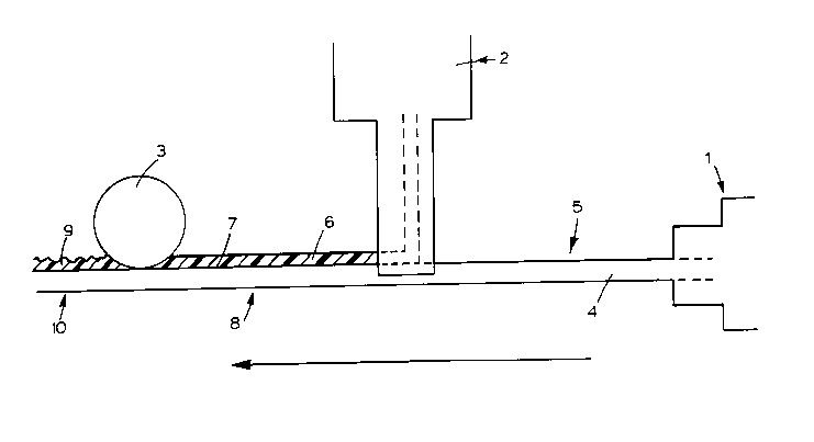
Figure 1 is a schematic drawing of apparatus for the method used
to form ornamented elongate members; and
Figure 2 is a section through a length of ornamented member.
Figure 1 shows apparatus for producing ornamented elongate
25 members, such as picture frame members. The apparatus consists of a
first extruder 1, a second extruder 2 and a pattern wheel 3. Means (not
shown) are provided for conveying the extruded materials through the
apparatus.

2 1 68321
A first core thermoplastic material 4, in this case blown
polystyrene, is extruded from the first extruder 1, and is conveyed along
path 5 to the second extruder 2, during which time the material cools to
form a substantially solid, rigid core for the frame member. The second
5 extruder 2 extrudes a second thermoplastic material 6, in this case
styrene, as a decorative material along the length of the core material 4.
The temperature of the decorative material 6 is such as to melt the surface
of the first material 4, enabling a firm bond to be formed at the interface
7 between the two materials.
The core and decorative materials are then fed along path 8, kept at
a temperature such that the decorative material remains molten or at least
plastic, and under the pattern wheel 3. .This shapes the decorative
material, forming ornamentation 9. The ornamented materials are then
15 fed along path 10, where they are cooled to form a firmly bonded,
substantially rigid structure. This structure is then cut into lengths
suitable for use as frame members.
An additional step of pre-heating the surface of the core
20 thermoplastic material 4 which is to be bonded, may be introduced in path
5 after cooling has taken place, thereby siding the bonding process.
The cooling of the ornamented materials along path 10 may be
biased in order to prevent any bowing which may occur, and ensures the
25 forming of a firmly bonded, substantially straight and rigid structure.
Alternatively, the materials may, in combination with cooling, be
stressed along this path in such a way to counteract any tendency to bow,
thereby forming a firmly bonded, substantially straight and rigid
30 structure.

21 68321
Figure 2 shows a section through a portion of a frame member 11,
comprising the first thermoplastic material 4 bonded along the interface 7
with the second thermoplastic material 6, the second thermoplastic
5 material having ornamentation 9 on its unbonded surface. A variety of
ornamentation may be produced by simply changing the pattern wheel.
The materials used are chosen for their suitability for the items
being made. While in the embodiment described the materials are blown
10 polystyrene and styrene, it will be appreciated that other combinations are
possible. Indeed, as long as the materials are compatible, in that a firm
bond is formed between them, any suitable combination can be used. The
first material may be thermoplastic or thermosetting, as may the second
material. Materials other than plastics may also be used.
In a modification, not shown, the first and second materials in path
8 may be cooled to form a firm bond between them, and a third material
extruded onto a surface of the second material. The third material may
then be shaped, and the first, second and third materials cooled to form a
20 firm bond between the second and third materials, and cut into lengths as
previously described. It will be appreciated that a number of layers may
be built up in this way, where the second, third etc. layer may cover part
or all of the preceding layer, and where one or more layers may be
shaped.
In a further modification, also not shown, the first material may be
a thermosetting material, and chemical treatment applied in path 5,
changing the surface of the first material so that a firm bond may be
formed between it and the second material. As before, a number of layers
30 may be built up in this way.

2 1 6832 1
Although the manufacture of picture frame members has been
described, this method may be used in the production of other items, such
as dado rails and other decorative items.

Representative Drawing
A single figure which represents the drawing illustrating the invention.
Administrative Status

2024-08-01:As part of the Next Generation Patents (NGP) transition, the Canadian Patents Database (CPD) now contains a more detailed Event History, which replicates the Event Log of our new back-office solution.

Please note that "Inactive:" events refers to events no longer in use in our new back-office solution.

For a clearer understanding of the status of the application/patent presented on this page, the site Disclaimer , as well as the definitions for Patent , Event History , Maintenance Fee  and Payment History  should be consulted.

Event History

Description Date
Inactive: IPC assigned 2022-01-11
Inactive: First IPC assigned 2021-09-29
Inactive: IPC assigned 2021-09-29
Inactive: IPC removed 2021-09-29
Inactive: IPC assigned 2021-09-29
Inactive: IPC expired 2019-01-01
Inactive: IPC removed 2018-12-31
Inactive: IPC from MCD 2006-03-12
Time Limit for Reversal Expired 2005-01-31
Application Not Reinstated by Deadline 2005-01-31
Deemed Abandoned - Failure to Respond to Maintenance Fee Notice 2004-01-29
Amendment Received - Voluntary Amendment 2003-01-02
Inactive: Application prosecuted on TS as of Log entry date 2002-11-21
Letter Sent 2002-11-21
Inactive: Status info is complete as of Log entry date 2002-11-21
All Requirements for Examination Determined Compliant 2002-11-05
Request for Examination Requirements Determined Compliant 2002-11-05
Application Published (Open to Public Inspection) 1996-08-01

Abandonment History

Abandonment Date Reason Reinstatement Date
2004-01-29

Maintenance Fee

The last payment was received on 2002-10-24

Note : If the full payment has not been received on or before the date indicated, a further fee may be required which may be one of the following

  • the reinstatement fee;
  • the late payment fee; or
  • additional fee to reverse deemed expiry.

Patent fees are adjusted on the 1st of January every year. The amounts above are the current amounts if received by December 31 of the current year.
Please refer to the CIPO Patent Fees web page to see all current fee amounts.

Fee History

Fee Type Anniversary Year Due Date Paid Date
MF (application, 2nd anniv.) - standard 02 1998-01-29 1997-11-26
MF (application, 3rd anniv.) - standard 03 1999-01-29 1998-11-19
MF (application, 4th anniv.) - standard 04 2000-01-31 1999-12-01
MF (application, 5th anniv.) - standard 05 2001-01-29 2000-12-20
MF (application, 6th anniv.) - standard 06 2002-01-29 2001-10-24
MF (application, 7th anniv.) - standard 07 2003-01-29 2002-10-24
Request for examination - standard 2002-11-05
Owners on Record

Note: Records showing the ownership history in alphabetical order.

Current Owners on Record
REDDIPLEX GROUP PLC
Past Owners on Record
PETER LAWRENCE BOOT
Past Owners that do not appear in the "Owners on Record" listing will appear in other documentation within the application.
Documents

To view selected files, please enter reCAPTCHA code :


To view images, click a link in the Document Description column. To download the documents, select one or more checkboxes in the first column and then click the "Download Selected in PDF format (Zip Archive)" or the "Download Selected as Single PDF" button.

List of published and non-published patent-specific documents on the CPD .

If you have any difficulty accessing content, you can call the Client Service Centre at 1-866-997-1936 or send them an e-mail at CIPO Client Service Centre.


Document
Description 
Date
(yyyy-mm-dd) 
Number of pages   Size of Image (KB) 
Representative drawing 1998-03-19 1 6
Abstract 1996-01-28 1 15
Description 1996-01-28 7 232
Claims 1996-01-28 3 77
Drawings 1996-01-28 2 12
Reminder of maintenance fee due 1997-09-29 1 111
Reminder - Request for Examination 2002-09-30 1 116
Acknowledgement of Request for Examination 2002-11-20 1 176
Courtesy - Abandonment Letter (Maintenance Fee) 2004-03-24 1 175