Note: Descriptions are shown in the official language in which they were submitted.
_ WO 95/03761 ~ PCT/DE94/00890
Self-locking joint, in particular orthotic
joint
The invention concerns a self-locking joint, in
particular an orthotic joint, consisting of two
joining pieces connected by means of an axis of
rotation. The connection between the respective
orthotic sections and the joint is realized by means
of these joining pieces.
Joints on orthoses have a stabilizing effect. They
guide and support the movement of partially
paralysed patients (e.g. spina bifida) and those who
are unable to carry out their movements in a
controlled fashion. Such joints can be moved into a
locked state when intended to perform a supporting
function, and into an unlocked state when the
patient requires freedom of movement, for example,
when he or she wishes to sit down.
According to the state of the art, there are two
principal forms for such joints. Conventional joints
corEesponding to the Ferrari method of treatment are
locked by means of a simple drop bolt which prevents
a relative l.,ov~l.,ent of the short lever arms of-the
joining pieces towards each other in the area of the
joint's axis of rotation, or only permits very
limited l~L~-v~...ent. To unlock the joint, the drop bolt
has to be slid upwards, thereby releasing the joint.
However, owing to the body posture of the disabled
patient in the orthosis, very large moments act on
the locked joint and hence on the drop bolt, and
these moments make it impossible for the patient to
2 1 6837 1
WO 95/03761 - 2 - PCT/DE94/00890
unlock the joint and even require a major effort
from assistants.
The other form of joint for supporting hip movement
concerns the so-called reciprocating gait orthoses.
This joint includes a free-swinging element, while
one of the other joining pieces of the joint is
connected with a rocker (or Bowden cables) for
transmitting the mechanical forces from one hip
joint to the other. The joint is locked when a pin
engages in an articulated arm which turns about the
axis of rotation of the joint. When this pin is
disengaged, the same problems as outlined above also
occur.
Based on this state of the art, it is the object of
the present invention to provide a self-locking
joint, in particular an orthotic joint, which can be
unlocked with minimum effort so that it even
possible for the disabled patient to unlock the
joint himself or herself. --
According to the invention, this task is solved inthat each joining piece has a curved profile and
these curved profiles intersect at such a large
angle that a rolling body guided in both curved
profiles, and whose axis lies at the intersection of
the centre-lines of the curved profiles, is moved
freely along the centre-lines of the curved profiles
when one joining piece is rotated against the other,
and that a locked state of the joint brought about
through self-locking is achieved when the angle a
between the imaginary tangents to the centre-lines
applied to their intersection approaches zero and
the line connecting the centres of the circles of
curvature of the two curved profiles does not pass
through the axis of rotation of the joint at the
2 1 6837 1
-
Wo 95/03761 - 3 - PCT/DE94/00890
point of intersection or contact present in the
locked position.
The position of the curved profiles in the joining
pieces is selected such that they intersect at a
relatively large angle in the area where the joint
is intended to move freely. This angle must be large
enough so that the rolling body guided in the two
curved profiles does not become jammed between said
curved profiles, thereby locking the joint. If the
joining pieces are rotated against each other about
their axis of rotation, then the curved profiles are
brought into a position in which the angle of
intersection of the imaginary tangents applied-to
their intersection approaches zero. In this position
the rolling body is clamped between the two curved
profiles through the forces acting on the joining
pieces, i.e. said rolling body transmits the forces
from one joining piece to the other perpendicular to
the centre-lines of the curved profiles. In this
position, no forces (tangent intersection angle
equal to zero) or virtually no forces (tangent
intersection angle almost zero) act on the rolling
body in the direction of the centre-lines of-the
curved profiles so that only a small force is
necessary in order to move the rolling body into a
position in which it is again free to be be guided
in the curved profiles, i.e. the joint can be
unlocked with very little effort. The tangent angle
at which the locking effect commences depends, among
other things, on the mating of materials between
rolling body and curved profiles, as well as the
lubrication.
As the joint only requires a low force to trigger
unlocking, it could easily happen that an unwanted
unlocking might occur in certain situations, for
2t 68371
-
W0 95/03761 - 4 - PCT/DE94/00890
example, rapid successive load reversals; to counter
this, a force acts on the rolling body which holds
and secures the locked position reached in the case
of reciprocal movement of the joining pieces from
the unlocked to the locked state. This force can be
realized, for example, by gravity, a rubber band, a
spring or a magnet. The force required to trigger
unlocking of the joint is only increased very
slightly by this ret~;n;ng force.
Further advantageous arrangements of this solution
result from the subclaims 2 to 4.
In line with another solution according to the
invention, a joint of this nature is realized in
such a way that a pivot.is provided which at one end
links two connecting rods in an articulated manner,
whereby each of these connecting rods has an
articulated connection to a joining piece via pivots
which do not coincide with the a~is of rotation of
the joint, and one or both connecting rods lies
against a stop in the locked state of the joint;
said stop is arranged in such a way that the
connecting rods are almost--in a parallel position or
a little beyond that in this state, whereby a force
acting on one or both..connecting rods causes them to
reach their locked position. The locked position
here is reached when both the connecting rods
provided are in a parallel or near parallel
position. In this position, forces acting on the
joining pieces are transmitted via the two
connecting rods and the pivot linking these
exclusively or almost exclusively perpendicular to
the locus of the pivot. As a result, this is
virtually free from forces in the direction of its
locus determined by.the connecting rods. The
rem~;n~er of this solution corresponds to the
Wo 95/03761 - 5 - PCT/DE94/00890 2 1 6837 1
working mechanism of the solution described above,
making further explanations unnecessary at this
point.
A stop can also be provided for the first solution.
This can be formed by the end of one curved profile
or can be arranged independently of this.
Further advantageous arrangements of this solution
result from the subcla; m~ 6 and 7.
In an advantageous follow-up to the inventive idea,
a combination of the "curved profile solution" and
the "connecting rod solution" is provided in which
one of the two curved profiles is replaced by a
connecting rod in such a way that one of its ends is
hinged to the corresponding joining piece and its
other end is guided in the curved profile present in
the other joining piece by means of a rolling or
sliding body.
Although the invention described above and in the
following is related to joints for orthoses, it is
obvious that such self-locking joints can also be
employed for other applications, for example, for
hinged flaps or folding tables.
Furthermore, it is also possible to provide several
locking positions through a-corresponding
arrangement of the curved profiles or the
connecting-rod link to the joining pieces.
The invention is explained in more detail in the
following by means of embodiment examples. The
associated drawing shows:
21 68371
WO 95/03761 - 6 - PCT/DE94/00890
ig. 1.1 a side view of an orthotic joint having
two curved slots, in the unlocked
position,
ig. 1.2 the joint according to Fig. 1.1 in the
locked position,
ig. 2 a cross-section through a rolling body
according to Figs 1.1 and 1.2,
Fig. 3 a sketch o~ the-principle of an orthotic
joint having two connecting rods, in the locked
position,
ig. 4 a side view of an orthotic joint having
one curved slot and one connecting rod, in
the locked position,
ig. 4.1 a sketch of the principle according to
Fig. 4,
.ig. 4.2 a sketch of the principle of another
variation of this embodiment example,
ig. 5 the orthotic joint according to Fig. 4 in
the unlocked position, and
ig. 6 a perspective view of a joint according to
the invention in--the version having one
curved profile and one connecting rod for
reciprocating gait orthoses.
In the individual figures, identical parts or parts
having the same effect are given the same reference.
In the embodiment example illustrated in Fig. 1, the
joint is shown in the unlocked (Fig. 1.1), i.e.
2 1 6837 1
-
WO 95/03761 - 7 - PCT/DE94/00890
freely movable state, and in the locked state (Fig.
1.2). The joining pieces 1, 2 have adapters 3 for
accommodating and securing rails which are in turn
fixed to the back or leg sections of the orthosis.
As the orthosis as such is not the object of the
invention, these sections are not illustrated in any
of the figures.
The joining pieces 1, 2 have a common axis of
rotation 4 about which they can be pivoted against
each other. Not visible in the illustration is the
fact that joining piece 2 is forked. Joining piece 1
is placed within this fork. This arrangement can, in
principle, be seen in Fig. 6, the perspective
illustration of a different embodiment example; the
reader is referred to this illustration in order to
gain a better understanding of Fig. 1.
Each of the joining pieces 1, 2 is of such a size
that curved slots 5, 6 can be provided which take
the form of segments of a circular path and, for
example, can be manufactured in a simple manner by
means of an end mill. These curved slots 5, 6 are
included in such a way that they cross in the
predeter~;ned pivoting range of the joint, whereby
the curved slot 5, which can be seen from the side
view according to Fig. 1, is also present in the
rear forked section of the joining piece 2 in an
identical manner.
A rolling body 7 is guided in the curved slots 5, 6.
The width of the curved slots 5, 6 and hence the
diameter of the rolling body 7 is designed as large
as possible in order to minimize the friction. A
version of the rolling body 7 as shown in the cross-
section according to Fig. 2 also contributes to
reducing the friction. Fig. 2 shows three rotatable
21 68371
Wo 95/03761 - 8 - PCT/DE94/00890
rollers independent of each other, whereby the
rollers 8 run in the curved slots 5 of the front or
rear forked sections of joining piece 2, and roller
9 runs in the curved slot 6 of joining piece 1.
From the illustration according to Fig. l.l--it can
be seen that the curved slots 5 and 6 or their
centre-lines 10 and 11 respectively, intersect at a
relatively large angle in the unlocked position of
the joint. That guarantees free guiding of the
rolling body 7. The closer the position of the
joining piece 1 is to the locked position (Fig.
1.2), the smaller the angle of intersection, until
finally it reaches or almost reaches zero in the
locked position. In this position the joining piece
1 lies against a stop 12 located between the forks
of joining piece 2. This stop 12 is designed as a
cam so that the end position of joining piece 1 and
hence the size of the triggering force can be
adjusted. Instead of the stop 12, the end of the
curved slot 5 can also be used as a stop.
The locked position of joining piece 1 or,
respectively, rolling body 7 is secured by a rubber
band 13 which acts on the rolling body 7 via an
unlocking lever 14 and also holds said rolling-body
7 in the locked position. The unlocking lever 14 is
located in a slot provided in joining piece 1 (see
ref. No. 15 in Fig. 6 for concept) and can be
pivoted about a swivel pin 16 fixed in joining piece
1. The fork-shaped end of the lever (see Fig. 2)
accommodates the axle of the rolling body 7, while
the other end projects beyond joining piece 2. Fixed
to this end is the rubber band 13 which,
accordingly, is fixed to joining piece 2 for the
purpose of exerting a tensile force. -~
21 68371
Wo 95/03761 - 9 - PCT/DE94/00890
To unlock the joint, the free end of unlocking lever
14 is pressed downwards, whereby the rolling body 7
is moved out of its clamped position. The joint is
now free to move.
A particularly simple embodiment version of the
invention is illustrated in the sketch of the
principle according to Fig. 3. This joint also has
two joining pieces 1, 2 pivoting about a common axis
of rotation 4. Furthermore, there are two connecting
rods 16, 17 provided which are hinged together at
their one end via a pivot 18. At their other ends,
the connecting rods 16 and 17 are linked
respectively via an arm 19, forming a bent away
segment of joining piece 2, and a pivot 20 with
joining piece 2, and via a pivot 21 with joining
piece 1. _
The locked position of the joint is reached when the
connecting rods 16, 17 are located in a parallel or
near parallel position. In this position the
connecting rod 16 lies against a stop 12 which
prevents the joint moving further and beyond the
dead stop position. The locked position is secured
by a rubber band 13 fitted between joining piece 1
and pivot 18. To unlock the joint, the connecting
rods 16, 17 have to be pressed out of their parallel
position, and this likewise only requires a low
triggering force.
The principle of the pivot 18 corresponds to the
rolling body 7 (or rather its axle) of the previous
embodiment example, whereby in the one case the
restraint for this point (rolling body 7) is
achieved by way of two curved slots and in this case
by way of the two connecting rods 16 and 17 whose
end points describe circular paths relative to the
- 2168371
W0 95/03761 - 10 - PCT/DE94/00890
joining pieces 1 and 2 respectively, the radii of
which are in each case determined by the length of
the connecting rods 16 and 17 respectively.
A further embodiment example of the invention is
illustrated in Figs 4 and 5. This embodiment example
corresponds to a combination of the version
according to Figs 1 and 3. To clarify this
combination, besides Fig. 4 there is a sketch of the
principle (Fig. 4.1) corresponding to this
illustration.
From the illustrations it is clear that in the case
of this embodiment example, the curved slot 6 of the
embodiment example according to Fig. 1 has been
replaced by the connecting rod 17 from the
embodiment example according to Fig. 3. Of course,
it is also possible to proceed vice versa, i.e. to
replace curved slot 5 with connecting rod 16. This
variation is shown in ~ig 4.2.
As already seen in the embodiment example according
to Fig. 1, the joining piece 2 here is forked for
accommodating joining piece 1. The curved slot 5
illustrated is present in an identical form in both
forked sections. The rolling body 7 consists of two
rollers connected via an axis of rotation, with each
of said rollers being guided--in the two curved slots
5 of joining piece 2. At the same time, the
unlocking lever 14 forms the connecting rod
replacing the curved slot 6, whereby the length of
said connecting rod is determined by the distance
between the swivel pin 16 of the unlocking lever 14
and the centre of the axle for the rolling body 7.
The method of operation of this version of the joint
is adequately covered by the previous embodiment
2 1 6837 1
,.
WO 95/03761 - 11 - PCT/DE94/00890
examples, making further explanations at this point
superfluous.
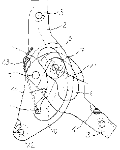
The embodiment example according to Fig. 6 shows
that the joint according to the invention can also
be immediately employed for reciprocating gait
orthoses. This version essentially corresponds to
the version according to Figs 4 and 5. However, in
contrast to that version, joining piece 2 is bent
here. Its bent end is connected to the mechanical
force transmission (Bowden cables or rocker). In
Fig. 6, for example, there is a connecting element
22 mounted on joining piece 2 so that it can rotate,
and leading to a rocker. In addition, in this
embodiment example there is a connecting element 23,
which can be freely pivoted on the joint's axis of
rotation 4, leading to the back section of the
orthosis.