Language selection

Search

Patent 2168538 Summary

Third-party information liability

Some of the information on this Web page has been provided by external sources. The Government of Canada is not responsible for the accuracy, reliability or currency of the information supplied by external sources. Users wishing to rely upon this information should consult directly with the source of the information. Content provided by external sources is not subject to official languages, privacy and accessibility requirements.

Claims and Abstract availability

Any discrepancies in the text and image of the Claims and Abstract are due to differing posting times. Text of the Claims and Abstract are posted:

  • At the time the application is open to public inspection;
  • At the time of issue of the patent (grant).
(12) Patent: (11) CA 2168538
(54) English Title: APPARATUS FOR ADJUSTING ONE OF THE BEARING BLOCKS OF A ROLLER
(54) French Title: DISPOSITIF PERMETTANT DE REGLER UN DES PALIERS D'UN ROULEAU
Status: Term Expired - Post Grant Beyond Limit
Bibliographic Data
(51) International Patent Classification (IPC):
  • B65G 39/09 (2006.01)
  • B65H 23/038 (2006.01)
  • D21F 1/36 (2006.01)
(72) Inventors :
  • BARTELMUSS, KLAUS (Austria)
  • BARTELMUSS, HEINZ (Austria)
(73) Owners :
  • KLAUS BARTELMUSS
  • HEINZ BARTELMUSS
(71) Applicants :
  • KLAUS BARTELMUSS (Austria)
  • HEINZ BARTELMUSS (Austria)
(74) Agent: SMART & BIGGAR LP
(74) Associate agent:
(45) Issued: 2004-02-17
(22) Filed Date: 1996-01-31
(41) Open to Public Inspection: 1996-09-24
Examination requested: 1999-12-20
Availability of licence: N/A
Dedicated to the Public: N/A
(25) Language of filing: English

Patent Cooperation Treaty (PCT): No

(30) Application Priority Data:
Application No. Country/Territory Date
A 520/95 (Austria) 1995-03-23

Abstracts

English Abstract

Apparatus for adjusting one of the bearing blocks (4) of a roller in a group of rollers, to support and move an endlessly moved belt, such as a screen strip, conveyor belt or the like, in a paper-making system, wherein the bearing block (4) is disposed on a final control element (3) which is adjustable in the direction of motion of the belt by means of an adjusting device (5) relative to a support frame (1), as a result of which the angular position of the roller supported in the bearing block (4) can be varied relative to the longitudinal direction of the belt. Therein, the final control elements is embodied by a car (3) which is provided with wheels (32) or the like and which can be moved about by the adjusting device (50 relative to the support frame (1) (Fig. 2).


French Abstract

Dispositif de réglage de l'un des supports de palier (4) d'un rouleau d'un ensemble de rouleaux destinés à soutenir et à déplacer une bande sans fin en mouvement, telle que la bande filtrante, la bande de transport ou similaire d'une installation de production de papier, le support de palier (4) étant disposé sur un élément de commande final (3) qui est réglable dans le sens de déplacement de la bande au moyen d'un deuxième dispositif de réglage (5), par rapport au bâti porteur (1), ce qui fait que la position angulaire du rouleau monté dans le support de palier (4) est variable par rapport à la direction longitudinale de la bande. Les éléments de commande finaux sont des chariots (3) pourvus de roulettes (32) ou similaires et pouvant être déplacés par un dispositif de réglage (50) par rapport au bâti porteur (1) (FIG 2).

Claims

Note: Claims are shown in the official language in which they were submitted.

CLAIMS:
1. An apparatus for adjusting a bearing block of a
rotating roller supporting a belt traveling in a given
direction of motion, comprising:
a final control element supporting a bearing block of
a roller, the final control element being a carriage
supported in a support frame and being movable relative to
the support frame in the given direction of motion of the
belt, for adjusting an angular orientation of the roller
relative to the belt;
an adjusting device for moving said carriage relative
to the support frame; and
a sliding carriage disposed in and being adjustable
relative to the support frame in the direction of motion of
the belt, and a second adjusting device for moving said
sliding carriage, said carriage being adjustably supported
in said sliding carriage in the given direction of motion
of the belt.
2. The apparatus according to claim 1, wherein said
carriage comprises wheels on which it is drivable.
3. The apparatus according to claim 1, which further
comprised guide wheels attached to said carriage for
defining a direction of motion thereof.
4. The apparatus according to claim 1, wherein said
carriage has two face ends, and said adjusting device is
disposed on one of said face ends.
5. The apparatus according to claim 1, wherein said
second adjusting device is an adjusting spindle.
6. The apparatus according to claim 3, wherein said
-8-

carriage is a plate having a top and an underside, the
bearing block being secured on said top, and including
guide wheels supported on and projecting from said
underside of said plate.
7. The apparatus according to claim 1, wherein said
carriage is a plate with end faces, and further comprising
an adjusting cylinder disposed on said carriage, said
adjusting cylinder having a piston and a piston rod
releasably connecting said piston to one of the end faces
of said plate.
8. The apparatus according to claim 7, wherein said
adjusting cylinder is located laterally of said carriage.
9. The apparatus according to claim 7, wherein said
adjusting cylinder is located laterally of said bearing
block secured to said carriage.
10. The apparatus according to claim 1, wherein said
sliding carriage is formed with two flanges, each having
one groove formed wherein for receiving and guiding support
devices for said carriage, and said sliding carriage
further hawing a groove formed therein for receiving and
guiding guide wheels disposed underneath said carriage.
11. The apparatus according to claim 10, wherein said
support devices are wheels laterally formed on said
carriage and rolling in said grooves of said flanges.
12. An apparatus or adjusting a bearing block of a
rotating roller supporting a belt traveling in a given
direction, of motion, comprising:
a final control element supporting a bearing block of
a roller, the final control element being a carriage
-9-

supported in a support frame and being movable relative to
the support frame in the given direction of motion of the
belt, for adjusting an angular orientation of the roller
relative to the belt, wherein said carriage is a plate
having a top and side faces, the bearing block being
secured on said top, and including wheels supported on said
side faces on which said carriage is drivable.
13. An improved apparatus for adjusting a bearing block of
a roller in a group of rollers supported in a support
frame, wherein the rollers support a moving endless belt in
a paper-production system, wherein the bearing block is
supported on a final control element which is adjustable
relative to the support frame in a longitudinal direction
of motion of the belt by means of an adjusting device, and
an adjustment of the final control element causes a defined
variation of an angular orientation of the roller supported
in the bearing block relative to the longitudinal direction
of the belt, the improvement which comprises:
the final control element being a carriage having
wheels attached thereto, and including an adjusting device
for moving said carriage relative to the support frame.
14. The apparatus according to claim 13, wherein the belt
is a screen strip in a paper mill.
15. The apparatus according to claim 13, wherein the belt
is a conveyor belt in a paper mill.
-10-

Description

Note: Descriptions are shown in the official language in which they were submitted.


216$538
WRA 28455
APPARATUS FOR ADJUSTING ONE OF THE
BEARING BLOCKS OF A ROLLER
The present invention relates to an apparatus for adjusting
one of the bearing blocks of a roller in a group of rollers,
to support and move an endlessly moved belt, such as a
screen strip, conveyor belt or the like, in a paper-making
l0 system, wherein the bearing block is disposed on a final
control element which is adjustable in the direction of
motion of the belt by means of an adjusting device relative
to a support frame, as a result of which the angular
position of the roller supported in the bearing block can be
varied relative to the longitudinal direction of the belt.
In systems which are embodied with an endless moving belt,
which is guided via a number of rollers disposed side by
side, as in the case of a paper-making system which has a
2o screen strip that is guided via a number of successive
rollers, it is a requirement that the travel direction of
the belt exactly match the direction normal to the axes of
the roller group. Conversely, if because of irregularities
of the belt or for other reasons the longitudinal direction
of the belt deviates from the feed direction of the roller
group, causing the direction of motion of the belt to form
an acute angle with the feed direction of the roller group,

WRA 28455
this not only leads to excessive loads on the belt, but the
belt can also creep laterally out of the roller group area,
resulting in functional problems.
It is known to provide a measuring instrument for monitoring
the direction of motion of a belt which is guided via a
groups of rollers, by which instrument excessive deviations
in the direction of motion of the belt from the feed
direction of the roller group are detected, so that measures
can then be taken to correct the direction of motion of the
belt. A correction can be made by changing the angular
position of one or more of the rollers of the roller group
slightly.
To be able to vary the alignment of one roller in a group of
rollers, it is known to embody one of the two bearing blocks
as adjustable in the longitudinal direction of the roller
group. To that end, a piston-cylinder device is disposed
below the bearing block; the cylinder below the bearing
block is rigidly secured in the undercarriage of the system,
and the bearing block is also supported by the piston, which
is adjustable inside the cylinder in the feed direction of
the roller group. As a result, by adjusting the piston, the
angular position of the roller supported by this bearing
block can be adjusted relative to the feed direction of the
roller group, and as a result the direction of motion of the
belt guided via this roller can be varied.
-2-

' "r 2 ~ 6 ~ 5 ~ g WRA 28455
This known apparatus is disadvantageous, however, because
the forces absorbed by the bearing block are transmitted via
the piston to the cylinder, thus dictating a heavy load on
the seals disposed between the piston and the cylinder.
Another disadvantage of this known apparatus is that the
piston-cylinder device is located below the associated
bearing block, and hence is poorly accessible for
maintenance or repair.
l0
The object of the present invention is accordingly to create
an apparatus for adjusting one of the bearing blocks of a
roller in a group of rollers for supporting and moving an
endlessly moving belt, by which the disadvantages of the
is known apparatus are avoided. This is attained in accordance
with the invention in that the final control element is
embodied by a car which is provided with wheels or the like
and which can be moved about by the adjusting device
relative to the support frame. Since thus the supporting
20 device for the bearing block is formed by a car which is
movable by means of a separate adjusting device, the loads
exerted by the bearing block on the supporting device are
transmitted directly to the supporting frame. Because of
the adjusting device, by comparison, only the rolling
25 resistance of the car, which depends on the magnitude of the
loads exerted by the bearing block, has to be overcome in
order to adjust the car.
-3-

2~ 6g~3g WRA 28455
Preferably, the car is also embodied with guide wheels.
Moreover, the adjusting device is preferably disposed on one
of the ends of the car. In a preferred embodiment, a
carriage is disposed in the support frame and is adjustable
relative to the support frame in the direction of motion of
the belt by means of a second adjusting device, and in which
carriage the car is also adjustable in the direction of
motion of the belt. As a result, a preadjustment of the car
to can be done.
In other preferred characteristics, the car is embodied as a
plate on whose top the bearing block is secured and one
whose side faces the wheels of the like are supported, and
the guide wheels protrude from the underside of the plate.
Moreover, an adjusting cylinder can be disposed on the
carriage, its piston being disconnectably connected to one
of the end faces of the plate by means of a piston rod. In
particular, the adjusting cylinder is located laterally
outside the car, or outside the bearing block secured to the
car. Also, the carriage is preferably embodied with two
flanges, which are each provided with one groove in which
the wheels or the like are guided, and it is also embodied,
underneath the car, with a groove into which the guide
wheels protrude. The second adjusting device may be
embodied as an adjusting spindle.
-4-

X168538 WRA 28455
An apparatus according to the invention is described in
detail below, in terms of an exemplary embodiment shown in
the drawing.
Shown are:
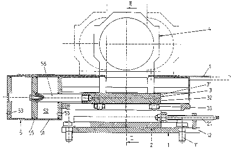
Fig. 1, an apparatus according to the invention in axial
section, and Fig. 2, the apparatus of Fig. 1 in a section
taken along the line II-II of Fig. 1.
l0 An apparatus according to the invention has a supporting
plate 1, which is secured by means of screw bolts 11 to a
frame of a system that has a number of rollers for
supporting and moving an endless belt. Since the supporting
plate 1 is provided with slits 12 through which the screw
bolts 11 pass, it can be adjusted in the direction of motion
of the group of rollers. As can be seen from Fig. 2, the
supporting plate 1 is embodied with flanges 13 which
protrude upward at the sides and in which a carriage 2 is
guided that is adjustable, again in the direction of motion
2o of the group of rollers, by means of a spindle 21.
The carriage 2 is provided in its lower region with a
boxlike profile 22, which is guided between the flanges 13
in the supporting plate 1. In its upper region, the
carriage 2 is embodied with two lateral, upward-protruding
flanges 23, which are provided on their insides with grooves
24 that serve to guide a car 3. A bearing block 4 is
-5-

._. ~~6$5~~ WRA 28455
rigidly secured to the car 3. The car 3 has a plate 31,
which in the region of its two side faces is embodied with
wheels 32 that are guided in the grooves 24. It is also
provided, on its underside, with a further group of wheels
33, which are guided in a groove 25 of the carriage 2.
Adjustment of the car 3 is done by a piston-cylinder device
5 which is disposed laterally outside the bearing block 4.
This device comprises a cylinder 51, whose inner chamber 52
l0 can be acted upon by a pressure medium via openings 53. A
piston 55 is disposed inside the cylinder chamber 52 and is
adjustable by feeding the pressure medium to the cylinder
51. The piston 55 is disconnectably connected to the
supporting plate 31 of the car 3 by means of a piston rod
56. The entire apparatus is surrounded by a housing 6.
The mode of operation of this apparatus is described below:
The carriage 2 is adjustable by means of the spindle 21 into
2o a position such that the bearing block 4 assumes a middle
position, in which the roller supported in it forms a right
angle to the feed direction of the group of rollers. If, to
correct the motion of the belt which rests on this roller,
the angular position of the roller relative to the feed
direction of the group of rollers must be adjusted, then the
inner chamber 52 of the cylinder 5 is acted upon with a
pressure medium via one of the openings 53, and the piston
-6-

WRA 28455
55 is thereby adjusted. As a result, the carriage is moved
by means of the piston rod 56, and hence the bearing block 5
is likewise adjusted in the direction of motion of the group
of rollers and for example assumes one of the positions
shown in dashed lines in Fig. 1; as a result, the angular
position of the roller supported in the bearing block 4 is
adjusted relative to the feed direction of the group of
rollers. By this means, a correction of the direction of
motion of the belt is made.
l0
Since the loads absorbed by the bearing block 4 are
transmitted to the carriage 2 via the wheels 32 of the car
3, the drive for the car 3 need merely overcome the
attendant rolling friction. Since the drive cylinder 5 is
disposed laterally outside the roller supported by the
bearing block 4, it is easily accessible for maintenance
purposes. Since moreover the drive 5 is disconnectably
connected to the car 3, it can be removed quickly in the
event of functional problems and replace by a drive that is
properly functional. Preferably, in a group of rollers via
which a belt is guided, one of the rollers is adjustable.

Representative Drawing
A single figure which represents the drawing illustrating the invention.
Administrative Status

2024-08-01:As part of the Next Generation Patents (NGP) transition, the Canadian Patents Database (CPD) now contains a more detailed Event History, which replicates the Event Log of our new back-office solution.

Please note that "Inactive:" events refers to events no longer in use in our new back-office solution.

For a clearer understanding of the status of the application/patent presented on this page, the site Disclaimer , as well as the definitions for Patent , Event History , Maintenance Fee  and Payment History  should be consulted.

Event History

Description Date
Inactive: Expired (new Act pat) 2016-01-31
Inactive: Office letter 2007-05-11
Inactive: Entity size changed 2007-03-26
Inactive: Corrective payment - s.78.6 Act 2007-02-01
Inactive: IPC from MCD 2006-03-12
Grant by Issuance 2004-02-17
Inactive: Cover page published 2004-02-16
Pre-grant 2003-12-05
Inactive: Final fee received 2003-12-05
Notice of Allowance is Issued 2003-10-14
Letter Sent 2003-10-14
Inactive: Approved for allowance (AFA) 2003-10-02
Amendment Received - Voluntary Amendment 2003-06-10
Inactive: S.30(2) Rules - Examiner requisition 2003-01-16
Amendment Received - Voluntary Amendment 2000-02-09
Inactive: Application prosecuted on TS as of Log entry date 2000-01-14
Letter Sent 2000-01-14
Inactive: Status info is complete as of Log entry date 2000-01-14
All Requirements for Examination Determined Compliant 1999-12-20
Request for Examination Requirements Determined Compliant 1999-12-20
Application Published (Open to Public Inspection) 1996-09-24

Abandonment History

There is no abandonment history.

Maintenance Fee

The last payment was received on 2003-11-17

Note : If the full payment has not been received on or before the date indicated, a further fee may be required which may be one of the following

  • the reinstatement fee;
  • the late payment fee; or
  • additional fee to reverse deemed expiry.

Please refer to the CIPO Patent Fees web page to see all current fee amounts.

Owners on Record

Note: Records showing the ownership history in alphabetical order.

Current Owners on Record
KLAUS BARTELMUSS
HEINZ BARTELMUSS
Past Owners on Record
None
Past Owners that do not appear in the "Owners on Record" listing will appear in other documentation within the application.
Documents

To view selected files, please enter reCAPTCHA code :


To view images, click a link in the Document Description column. To download the documents, select one or more checkboxes in the first column and then click the "Download Selected in PDF format (Zip Archive)" or the "Download Selected as Single PDF" button.

List of published and non-published patent-specific documents on the CPD .

If you have any difficulty accessing content, you can call the Client Service Centre at 1-866-997-1936 or send them an e-mail at CIPO Client Service Centre.


Document
Description 
Date
(yyyy-mm-dd) 
Number of pages   Size of Image (KB) 
Representative drawing 1998-05-04 1 35
Claims 2003-06-10 3 113
Representative drawing 2003-10-03 1 22
Cover Page 2004-01-15 1 53
Description 1996-05-28 7 242
Claims 1996-05-28 3 73
Cover Page 1996-05-28 1 18
Abstract 1996-05-28 1 21
Drawings 1996-05-28 2 56
Reminder of maintenance fee due 1997-10-01 1 111
Acknowledgement of Request for Examination 2000-01-14 1 180
Commissioner's Notice - Application Found Allowable 2003-10-14 1 159
Fees 2002-12-05 1 34
Fees 2003-11-17 1 35
Correspondence 2003-12-05 1 29
Fees 1998-12-17 1 33
Fees 2001-12-04 1 33
Fees 2000-11-29 1 33
Fees 1997-12-04 1 33
Fees 1999-11-22 1 27
Fees 2004-11-16 1 28
Fees 2005-11-17 1 26
Fees 2007-01-31 1 29
Correspondence 2007-05-11 1 15
Fees 2007-11-28 1 29
Fees 2008-11-18 1 35