Note: Descriptions are shown in the official language in which they were submitted.
~ ~ ~ n ~ ~ ~ PCTrUS94/09574
W O 95/06934
ADVERTISING DISPLAY METHOD AND APPARATUS
BACKGROUND OF THE INVENTION
Field of the Invention:
The present invention relates to advertising,
particularly to methods and apparatus for sequentially
displaying multiple images in a single display.
Descri~tion of the Prior Art:
With the advent of modern display advertising,
limitations on advertising budgets and limited locations
for display to high densities of consumers, a demand has
arisen for displaying multiple advertisements at
individual popular display locations thereby enabling a
number of advertisers to benefit from a single location.
Numerous different methods and devices have been proposed
for preparing and displayinc such advertisements. Many
such devices involve relatively unwieldy mechanical
elements driven by complex drive mechanisms which require
a certain degree of mechanical precision. Thus, in
addition to the expense of original manufacture, the user
is often faced with expensive maintenance.
In addition, operation of these current drive
mechanisms tend to produce an undesirable amount of
noise. Typically, these devices are used in public
retail outlets or other public locations. ~he noise
level of the drive mechanism frequently predominates over
the background music being played at such locations.
This noise detracts from the overall environment sought
by the retailers at the location where the advertising
display is positioned.
wos5lo6s34 PCT~S94/09574
21~576 -2-
Display devices including templates with
patterns of apertures which define numbers, letters or
figures when they are illuminated by back lighting have
been described. See, e.g., Hildburgh, U.S. Patent No.
1,172,455, and Kass, U.S. Patent No. 2,982,038. There
have also been described display devices including
transparency sheets which have images thereon and which
are illuminated by back lighting and an overlay mask
which blocks the back lighting from illuminating certain
areas of the transparency sheets. See, e.g., Elvestrom,
U.S. Patent No. 3,000,125, Fukui, U.S. Patent No.
3,683,525, and Hasala, U.S. Patent No. 3,742,631.
In addition, devices have been proposed which
include a translucent image screen made up of a mosaic of
discrete images formed by relatively small interlaced
translucent pixels or window segments which are arranged
in uniform groups. The pixels corresponding to a
discrete image occupy the same relative position in each
group and bear corresponding magnitudes of translucency.
The image screen may then be covered with an opaque
screen having a uniform pattern of transparent display
apertures. The opaque screen blocks back lighting from
shining through the image screen except through the
display apertures. The uniformly patterned display
apertures are then aligned with pixels which correspond
to a discrete image and the discrete image is thereby
displayed due to the back lighting shining through the
image screen and display apertures. The opaque screen
may then be selectively shifted on the image screen such
that the display apertures align with the pixels of a
different discrete image. Thus, each discrete image may
be sequentially displayed.
21~$576
W O 95/06934 PCTrUS94/09574
A device of this general description is shown
in U.S. Patent No. 4,897,802 to Atkinson, et al.,
assigned to the assignee of the present application.
While the device described in that patent exhibits
excellent operational characteristics, it is desirable to
provide a more economical and reliable drive and
registration system which enables convenient and accurate
adjustment of registration between the image screen and
mask and enables relatively noise free operations.
While these devices are fit for their intended
purpose, they do not provide a multiple image advertising
display design having low manufacturing tolerances,
extended maintenance free operation, and need for only
minor on-site adjustments. Furthermore, these devices do
not provide sufficiently quiet operation which is
desirable for the advertising display to blend in with
the overall environment in which it is located.
SUMMARY OF THE INVENTION
The present invention is directed to an
advertisinq display method and apparatus that displays
multiple images wherein the exchange from one image to
another is fast, accurate, and quiet. The image exchange
of the present invention enables sequential display of
different images which can give the impression of
animation.
The present invention preferably includes a
back-lit translucent image screen having a mosaic of
pixels comprising discrete composite images and having an
overlying opaque mask sheet having a plurality of display
apertures. The image screen comprises pixels of a
discrete image interspersed with pixels of other discrete
W O 95/06934 ~ PC~rrUS94/09574
2 1 6~ 5 7 6 _4 _
images. The pixels are arranged in uniform groups of
pixels such that pixels from any one image are located in
corresponding positions in each group. The pixels are
generally themselves polygonal and may be arranged in
polygonal groups to define rhomboid or, preferably,
square shapes. The apertures in the mask sheet comprise
corresponding rhomboid or, preferably, square shapes.
The images are displayed by relative movement
between the image screen and the overlying opague mask
sheet such that the display apertures of the mask sheet
align with pixels corresponding to a particular image to
be displayed. When the image screen is illuminated from
its back side the opaque mask sheet blocks light from
projecting through the body of the image screen except
for the pixels aligned with the apertures. Thus, when
the apertures in the mask sheet register over a specific
set of pixels, a discrete image comprising a composite of
the illuminated pixels is displayed.
The present embodiment also includes a platen
upon which the translucent image screen is adjustably
mounted. The platen is preferably formed with a central
cylindrically shaped convex curved rib structure to
support the image screen. The curved surface allows the
overlying mask sheet to be biased down at its edges to be
drawn into intimate contact with the central portion of
the image screen. The platen is movably attached to a
housing (or display box) which has a light mounted
therein such that the screen or sheet mounted on the
platen may be back-lit. The platen is restricted in
movement relative to the housing by a plurality of stops.
The stops restrain movement of the platen to within a
certain boundary. As described below, the platen moves
the translucent image screen in discrete steps with
W095/06934 2 16 8 5 7 ~ pcT~s94los574
--5--
respect to the opaque mask sheet, or vice versa, such
that the pixels on the image screen register with the
apertures of the mask sheet at the end of travel for each
step.
The present invention also includes a driver
attached to the display apparatus. The driver has an
eccentric cam which engages a pair of cam arms which are
attached to the platen. The platen is moved by the
interaction of the eccentric cam and the cam arms such
that the stops limit the extent of the platen's travel.
The stops are positioned such that the travel of the
platen is limited and stopped in a position where the
pixels on the image screen are aligned with the apertures
in the mask sheet thereby enabling display of one of the
discrete images on the screen. In addition, the
apparatus is provided with features which enable
adjustment of the relative positioning of the mask sheet
and the image screen to provide proper alignment between
the mask sheet and image screen. Once proper alignment
is achieved, shifting the image screen through
predetermined positions relative to the central mask
sheet, or vice versa, will serve to selectively display
the discrete images by screening out all light being
projected through the image screen except for the light
being projected through the pixels of the discrete image
being displayed.
Other objects and features of this invent.on
will become apparent from consideration of the following
description taken in connection with the accompanying
drawings.
PCT~S94/09574
Woss/06934
2 1 6~ 5 7 6 -6-
BRIEF DESCRIPTION OF THE DRAWINGS
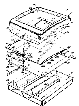
FIG. 1 is an exploded perspective view of a
first embodiment of a display apparatus of the present
invention;
FIG. 2 is a top plan view with a partial cut
away of the display apparatus shown in FIG. 1 with the
bezel removed;
FIG. 3 is a cross sectional view taken along
line 3-3 of FIG. 2 with the bezel in place;
FIG. 3A is a perspective view of a rib
structure for supporting the curved surface of the
platen;
FIG. 3B is an end view of the rib structure;
FIG. 3C is a perspective view of the platen
incorporating the rib structure;
FIG. 4 is a partial view taken along line 4-4
of FIG. 3 with the bezel in place;
FIG. 5 is a partial view taken along line 5-5
of FIG. 3;
FIG. 6 is a view taken along line 6-6 of FIG.
2;
FIG. 7 is a view taken along line 7-7 of FIG.
6;
FIGS. 8 - 11 are expanded diagrammatic views of
the cam and cam stops of the present invention showing
the cam in four different positions respectively;
FIG. 12 is a detailed view of a cam arm of the
present invention;
FIG. 13 is a cross sectional view taken along
line 13-13 of FIG. 12;
FIG. 14 is a cross sectional view taken along
line 14-14 of FIG. 12;
FIG. 15 is a cross sectional view taken along
line 15-15 o~ FIG. 12:
W O 95/06934 2 1 6 8 ~ 7 ~ PCTrUS94/09574
FIGS. 16 - 19 are diagrammatic views showing
platen stop blocks of the present invention in four
different positions with respect to stop edges;
FIG. 20 is a view, partially cut away, showing
a second embodiment of the present invention with the
bezel removed;
FIG. 21 is a view of the eccentric cams of the
embodiment shown in FIG. 20;
FIG. 22 is a view showing a third embodiment of
the present invention with the bezel removed;
FIG. 23 is a cross sectional view taken along
line 23-23 of FIG. 22; and
FIGS. 24-27 are diagrammatic views showing the
platen of second and third embodiments in four different
positions with respect to a frame.
DETAILED DESCRIPTION OF THE PREFERRED EMBODIMENT
Referring to the drawings, particularly FIGS.
1 - 6, the preferred embodiment of the display apparatus
of the present invention 10 includes, generally, an open
top housing 12 upon which is mounted a generally square
frame 14 defining a border. The frame 14 provides an
outwardly facing, generally planar surface 16 (FIGS. 1
and 3) having centrally positioned along top and bottom
edges thereof respective stop blocks 18. The stop block
18 is shown as being generally circular, but it could be
of any workable shape (FIGS. 1, 2, 3 and 5). A hinge 19
provides a connection between the housing 12 and the
frame 14 along one side. The hinge 19 enables easy
access to the interior of the housing 12.
Referring to FIGS. 1 and 2, a rectangular in
plan view platen 20 is shiftably mounted on the planar
outwardly facing surface 16 of the frame 14. The platen
W095/06934 PCT~S94/09574
2 1 ~ ~ 5 ~ 6 -8-
20 includes respective triangular tether tabs disposed
centrally along its respective top and bottom edges
thereof to be formed with respective generally s~uare
stop block aperture 22a and 22b (FIGS. 1, 2, 3 and 5) for
receipt of the respective stop blocks 18 of the frame 14.
As shown in FIGS. 16 - 19, the walls of the respective
stop block apertures 22a and 22b limit the possible
movement of the respective stop blocks 18 and thereby
limit movement of the platen 20 on the frame 14. The
stop blocks 18 and respective stop block apertures 22a
and 22b are sized such that the movement of the platen 20
is limited to approximately one-half (1/2) millimeter in
any one of four orthogonal directions (i.e. left (FIG.
16), down (FIG. 17), right (FIG. 18), and up (FIG. 19))
and, therefore, limited to one (1) millimeter total
either vertically or horizontally. It is preferable that
the top block aperture 22a which controls the vertical
travel (generally the stop block aperture 22a is at the
top of the device 10 when mounted in a vertical
orientation shown in FIG. 3) is precisely sized and that
the other stop block aperture 22b (generally the stop
block aperture 22b is at the bottom of the device 10 when
in use) be oversized in vertical height so as not to
constrain travel of the platen 20 in a vertical
direction. By having the bottom stop block aperture 22b
oversized in this way, the top aperture 22a provides the
sole control of vertical travel thereby preventing
differential thermal coefficients of expansion from
reducing the vertical travel as the temperature changes.
Formed distally of the respective apertures 22a and 22b
are respective clearance windows 55 aligned with the
respective posts 54.
Mounted in stacked relation on the platen 20 is
an image screen 24 which is shifted with the platen 20
W095/06934 2 1 6 ~ 5 7 6 PCT~S94/09574
_g_ .
relative to an overlying screening mask 26 for the
purpose of ~electively screening out certain portions of
the screen 24 to provide for projection through other
portions thereof. Although it is preferable that the
platen 20 carry the image screen 24 and move it relative
to the mask 26, the platen 20 could carry the mask 26 and
move it relative to the screen 24. Coupled between the
platen 20 and the frame 14 is an eccentric drive
mechanism 28 (FIG. 1) for driving orthogonal coupling
arms 30 and 32 to sequentially shift the platen 20, and
consequently the image screen 24, about a path to four
extreme positions defined by the limits of the walls of
the stop block apertures 22a and 22b confining movement
of the stop blocks 19 (see FIGS. 16 - 19).
Referring to FIGS. 1 and 3, a bezel 34
comprises a generally square rim which overlies the top
sides of the peripheral edges of the platen 20 and
housing 12 and is constructed with a downward and
outwardly flared peripheral skirt 36. The bezel 34 is
formed with a centrally positioned plate aperture 38
which may have mounted therein a transparent plastic
protective plate 40. Referring to FIG. 3, the bezel 34
is mounted on the housing 12 by means of a hook 35 and
squeeze spring arrangement, generally designated 37. The
hook 35 is somewhat Z shaped, projecting rearwardly from
the interior of the bezel 34 near its top edge and turned
inwardly on its distal extremity to hook over a rear lip
in the housing 12 to limit downward movement of such
bezel relative to such housing. The squeeze spring 37 is
interior of the bezel 34 near its bottom edge and
projects rearwardly to be formed with a turned back clasp
- biased upwardly to span the combined peripheral lip 46 of
the housing 12 and marginal edge of the frame 14 and then
tapers rearwardly and downwardly to form a finger grasp.
wos5/o6s34 PCT~S94/09~74
2 1 6 ~ ~ 7 ~ -lo-
To remove the bezel 34 from the housing 12, the squeeze
spring 37 is pulled toward the lower run of the skirt 36
(FIG. 3) of the bezel 34 thereby detaching the spring 37
from engagement with the housing 12 and frame 14.
In practice, the device of the present
invention 10 is typically suspended in a generally
vertical plane with the device 10 positioned such that
the edge of the device 10 nearest the viewer in FIG. 2 is
in a bottom position.
The image screen 24 may be fabricated in any
desirable well-known manner such that the screen 24
comprises interlaced sets of pixels wherein each set of
pixels comprises a composite image when light is
transmitted therethrough. The screening mask 26 may also
be fabricated in any desirable well-known manner such
that the mask 26 is opaque and has a plurality of
apertures or transparent windows which are positioned and
sized to correspond to the individual sets of pixels.
The pixels of each set of pixels on the image screen 24
are interlaced and positioned in groups wherein each
group contains a pixel which corresponds to each set.
The apertures of the mask 26 are spaced and sized such
that they may be precisely positioned over any one set of
pixels such that light may be projected therethrough to
display the set of pixels and thereby the corresponding
composite image. Arrangements like this are well-known
and described in U.S. Patent No. 4,897,802 to Atkinson et
al., so that no further description is required here.
The mask 26 includes clearance apertures 65 (FIGS. 1, 3
and 4) aligned over the respective registration pins 63.
As shown in FIG. 1, the housing 12 is generally
pan-shaped and substantially rectangular in plan view.
W095/06934 2 1 6 ~ ~ 7 6 PCT~S94/09574
--11--
The housing 12 is formed with the peripheral edge flange
46 (FIGS. 1 and 3) and has an integrally molded pair of
side by side elongated reflective channels 48 (FIG. 1)
configured to centrally receive fluorescent lighting
tubes 50. The reflective channels 48 reflect light
produced by the lighting tubes 50 to the image screen 24.
The frame 14 includes attachment post apertures
52 centrally positioned along the respective top and
bottom runs (FIGS. 1, 3 and 6) for projection outwardly
therethrough of the projecting ends of respective posts
54 pivotally carried on their back ends in respective cup
shaped post housings 76 to be biased longitudinally
upwardly and downwardly, respectively, by respective coil
compression springs 77a and 77b (FIG. 3). Similarly, the
platen includes attachment post clearance apertures 55
aligned over the respective frame apertures 52. The
clearance apertures 55 are sized to accommodate the
adjustment posts 54 which extend therethrough such that
the posts 54 do not contact the edges during movement of
the stop blocks 18 in relation to the stop apertures 22.
The attachment posts 54 include respective
circumferential grooves 56 around the top ends thereof
(FIGS. 3 and 7). Extending from the top and bottom
marginal edges of the screening mask 26 are triangular
shaped attachment bindings 58 (FIGS. 1 - 4). The
attachment bindings 58 include centrally positioned
apertures 60 (FIGS. 1 and 4) which engage the grooves 56
(FIG. 3) of the attachment posts 54 and thereby hold the
mask 26 to the frame 14. As shown in FIGS. 1 and 3, the
image screen 24 includes centrally positioned along both
its top and bottom edges a registration aperture 61 (FIG.
1). The apertures 61 are generally sized and positioned
to fit over respective registration pins 63 disposed on
the opposite ends of the platen 20 in alignment with the
woss/06s34 PCT~S94/09574
21685~6 -12-
respective apertures 22a and 22b. It is preferable that
the apertures 61 be sized such that the aperture at the
top of the screen 24 fits tightly around its ~ssociated
registration pin 63 to establish vertical ~nd horizontal
positioning of the screen 24 on the platen 20. It is
also preferable that the aperture 61 at the bottom of the
screen 24 fit on its associated registration pin 63 such
that the horizontal movement of the screen 24 is more
limited than the vertical movement. The aperture 61 and
pin 63 arrangement enables the image screen 24 to be
moved relative to the mask 26 and prevents the image
screen 24 from rotating around the registration pin 63 at
the top of the platen 20.
As shown in FIG. 1, the frame 14 is formed in
one corner with a clearance opening 62 having the drive
mechanism 28 mounted thereunder. Such drive mechanism
includes a driving motor 66 having a drive shaft 64
projecting upwardly through the clearance hole 62 to
mount thereon a wedge shaped drive cam 86 having an
arcuate cam surface thereon. The frame 14 also includes
a pair of aligned elongated clearance notches 68 at the
opposite ends of one side (FIGS. 1, 2 and 6). Knurled
thumb wheels 70 are carried on respective axial threaded
shafts journaled through respective mounting brackets on
the bottom side of such frame (FIG. 7) such that the
respective upper sectors thereof project through such
clearance slots.
The clarity of the images being shown by light
projecting through pixels of the image screen 24 may be
adjusted by adjusting the positioning of the mask 26
vertically or horizontally relative to the image screen
24. Referring to FIGS. 6 and 7, the posts 54 are engaged
medially by the turn back of a hook 75 to be biased to
W095/06934 2 16 ~ ~ 7 ~ PCT~S94/09574
one side by a coil spring 73 connecting such hook to the
frame 14 and an elongated slot 71 in one end of a link 72
connected on its opposite end to a thumb wheel 70. The
spring 73 and connector plate 75 arrangement provides
tension to maintain the attachment/adjustment post 54 at
the end of the slot 71 in the adjustment shaft 72 so that
the adjustment link 72 controls the lateral position of
the top end of the adjustment post 54 and hence the mask
26.
Referring to FIGS. 2, 3 and 4, a U-shaped
adjustment wheel 78 is coupled to an adjustment clip
spring 80 is mounted to the top of the frame 14 adjacent
the top post 54 and is formed by a mount leg 81 and an
adjustment leg 83. A vertical adjust knob 78 is carried
on one end of a threaded shaft screwed through a threaded
bore in the leg 81 to abut on its free end against the
leg 83 to selectively urge it against the adjacent post
54 (FIG. 4) to, upon manipulation, adjust the position of
post 54 (up and down) thereby adjusting the vertical
positioning of the mask 26. Referring to FIG. 3, the
upper bias spring 77a is preferably stronger than the
lower bias spring 77b to provide a greater spring
constant and prevents the bias of the lower spring 77b
from overcoming the bias of the upper spring 77a and
pulling the upper adjustment post 54 away from the
adjustment clip spring 80. This enables the clip spring
80 to remain in control of the up and down positioning of
the upper adjustment post 54 and, thus, the mask 26. The
function of the upper bias spring 77a is to hold the
adjustment post 54 firmly in contact with the clip spring
80. The function of the lower bias spring 77b is to
- provide tension to hold the mask 26 securely in place
between the two adjustment posts 54.
PCT~S94/Oss74
W0 95,06934 ~- - 2 ~ 6 8 5 7 ~
The platen 20 is preferably formed with a
central cylindrical curved surface 84 (FIGS. 1 and 3),
which is preferably supported by a rib structure (FIGS.
3A, 3B and 3C). The rib structure has horizontally
disposed upper and lower ribs 85a, medial rib 85b, and a
central rib 85c secured to the base of the platen 20.
Ribs 85a are of a first short height, ribs 85b are
taller, and a center rib 85c is still taller. Using ribs
85 of different heights in this manner allows the platen
surface 84 to be attached thereto in a manner to deflect
it to the desired curvature. Importantly, the platen
surface 84 is secured (as by gluing) only to the center
tallest rib 85c. When the image screen 24 is mounted to
the platen 20, as described above, the platen surface 84
arcs downwardly (as shown by arrows 87 in FIG. 3B) to
rest against the ribs 85a and 85b to provide the desired
curved shape to the platen surface 84. The benefit of
this arrangement is that it minimizes any bowing of the
platen surface 84 between the ribs 85a and 85b, 85b and
85c, 85c and 85b, and 85b and 85a, and, therefore, allows
the image screen 24 and mask 26 to lie together in very
close contact and to achieve more accurate registration.
The rib structure and platen surface 84 thereby
provide a curved support surface for support of the image
screen 24 to be held in position by the mask 26 and by
the post 54 as described above. Referring to FIG. 3, it
is clear that the reception of the apertures 60 of the
binding 58 of the mask 26 onto the grooves 56 of the
attachment/adjustment posts 54 draws the mask 26 firmly
down over the platen surface 84 thereby pulling the
platen surface 84 into a curved position and pulling the
mask into intimate contact with the image screen 24 to
thereby help positively retain the image screen 24 in
contact with the cylindrically curved surface 84. This
W095/06934 2~ 6 ~ PCT~Ss41o9574
intimate contact facilitates a close spaced relationship
between the image screen 24 and the mask 26 ~uch that,
- upon precise alignment between the apertures of the mask
26 and image pixels of the screen 24, light will be
projected precisely through the apertures and aligned
pixels to thereby prevent what is termed parallax or
other unwanted distortion of the projected light.
The platen 20 is typically constructed of a
hard plastic, such as acrylic, having sufficient rigidity
to maintain its generally square shape in plan view (see
FIGS. 1 and 3C) and having a low coefficient of friction
to facilitate freedom of movement on the surface 16 of
the frame 14. As described above, movement of the platen
20 is limited by the interaction of the stop blocks 18
and the stop block apertures 22.
Turning now to the mechanism for controlling
movement of the platen 20 (FIGS. 1, 2 and 8 - 11), the
drive cam 86 (FIG. 2) is disposed to be rotatably
received within generally square-shaped apertures 90 and
92 formed in the respective proximate ends of each of the
coupling arms 30 and 32, respectively. The coupling arms
30 and 32 include attachment posts 102 at ends opposite
the apertures 90 and 92 (FIGS. 1 and 3). The coupling
arms 30 and 32 are attached to the platen 20 by engaging
attachment posts 102 with attachment apertures 101 of the
platen 20 (FIGS. 1, 2, 3 and 12). The coupling arms 30
and 32 are disposed substantially perpendicular to each
other with the apertures 90 and 92 overlying one another
as shown in FIGS. 1 and 2. The apertures 90 and 92 are
shown in FIGS. 8 - 11 in an expanded view with one
aperture located adjacent the other for the purposes of
simplifying the explanation of operation. The cam 86
must be constructed of sufficient thickness to project
~16857~
W095/06934 PCT~S94/09~74
-16-
into both apertures 90 and 92 when the arms 30 and 32 are
overlying one another.
Referrinq to FIGS. 8 - 11, the aperture 9o of
the horizontally disposed arm 30 includes parallel
follower slides 94 and 96 on opposite horizontal edges of
the aperture 90. The follower slides 94 and 96 are
preferably constructed of Teflon or other low-friction
material. The follower slides 94 and 96 are contacted by
the arcuate surface 88 of the cam 86 to drive the arm 30
up and down. The aperture 92 of the vertically disposed
arm 32 includes low-friction parallel follower slides 98
and 100 on opposite vertical edges of the aperture 92.
The follower slides 98 and lOo are also preferably
constructed of Teflon or other low-friction material and
are contacted by the arcuate surface 88 of the cam 86 to
drive the arm 32 right and left. As shown in FIGS. 8 -
11, the arcuate cam surface 88 may sequentially contact
- the follower slides 94, 96, 98 and 100 to move the arms
30 and 32 and thereby move the platen 20.
The same general description applies to arm 30
as both arms 30 and 32 are of similar construction. As
shown in FIGS. 12 and 14, arm 32 includes a rigid stem
104 which at one end (the end opposite the aperture 92)
is forked to define a pair of flat tines 106 formed with
an opening 108 therebetween (FIGS. 12 (dashed lines) and
14). Mounted over the forked end of the stem 104 is an
over-travel bracket 110 (FIG. 13). The bracket 110 is
generally U-shaped to form opposed, spaced apart flat
tines 112 which sandwich therebetween the forked end of
the stem 104 (FIGS. 13 and 14). The over-travel bracket
110 is pivotally connected to the stem 104 by means of a
pivot pin 114 (FIGS. 12 and 13). Pivot pins 114 are also
used to connect the arms 30 and 32 to the frame 14.
216~76
W O 95/06934 PCTrUS94/09574
- 17 -
Formed in the flat tines 112 of the over-travel
bracket 110 are aligned transverse slots 116 disposed in
general alignment with the opening 108 between the tines
106 of the stem 104 (FIGS. 13 and 14). Releasably
received and retained in the slots 116 is a coil
compression spring 118 (FIGS. 12 - 14). The spring 118
is retained in the opening 108 between the tines 106 such
that the bracket 110 is biased to a central neutral
position (as shown by solid lines in FIG. 12). As
mentioned above, arm 30 is of construction similar to
that of arm 32.
In operation, the present embodiment of the
invention is typically supplied to an advertising agency
or leasing entity and the image screen 24 is prepared to
provide a desired mosaic of images with corresponding
pixels oriented and configured in a manner which is known
to those skilled in the art. In practice, for the
preferred embodiment, the pixels are approximately one
(1) millimeter or .03937 inches square and the image
displayed is approximately 18 to 50 inches wide and 18 to
50 inches tall. This size provides a pleasing display
for the viewer. However, other sizes may be acceptable.
The image screen 24 preferably comprises pixels arranged
in a square pattern thereby requiring the screen 24 and
platen 20 to be moved through a one (1) millimeter by one
(1) millimeter square pattern (e.g. one millimeter to the
right, one millimeter down, one millimeter to the left,
and one millimeter up). If the pixels are of a different
size and/or shape, the pattern of movement will be
different. In this embodiment, the stop blocks 18 are
mounted on the frame 14 such that the platen may move one
(1) millimeter total in both the transverse and
longitudinal directions.
woss/06934 PCT~S94/09574
` ~ 216857'~
-18-
The motor 66 may be energized to move the
platen 20 to a position such that the apertures 22 of the
platen 20 engage the stop blocks 18 of the frame 14
(FIGS. 16 - 19). Generally, the stop blocks 18 will
engage two sides of the substantially square apertures
22. For example, when the platen 20 is moved to an upper
left position, the lower and right sides of the apertures
22 are engaged (see FIG. 16). When the platen 20 and,
consequently, the screen 24 are positioned, the relative
position of the mask 26 may easily be adjusted using
wheels 70 and 78 to assure proper registration between
the mask 26 and screen 24 such that the pixels of the
screen 24 are aligned with the apertures of the mask 26
to thereby provide for projection of a high quality
composite image. A transverse adjustment of the mask 26
may be easily achieved by, for instance, adjusting the
thumb wheels 70 of the adjustment shafts 72 to advance or
retract the adjustment post housings 74 to thereby shift
the mask 26 transversely as required for appropriate
alignment. In a similar manner, a longitudinal
adjustment may be achieved by adjusting wheel 78 (FIG. 2)
to pivot the leg 83 of the clip spring 80 to raise or
lower the adjustment post 54 and thereby shift the mask
26. The adjustment shafts 72 may be made of material
which will not inadvertently shift the mask 26 (e.g. when
exposed to an increase in temperature). The shafts 72
are preferably made from the same material as the frame
14. Acceptable material includes steel. Thus, if the
temperature changes, the expansion or contraction of the
frame 14 and the adjustment shafts 72 will be the same,
and there will be no net shift of the adjustment posts 54
or the mask 26. Once adjustment has been made, the bezel
34 may be conveniently snapped in position over the mask
26 and to the housing 12 as described above.
WO 9S/06934 216 8 5 7 ~ PCT/US94/09574
--19--
Once everything is adjusted, the motor 66 may
be energized to thereby rotate the cam 86 and move the
platen 20. The cam 86 moves the platen 20 and,
consequently, the image screen 24 as the cam 86 engages
the follower slides 94, 96, 98 and 100 of the coupling
arms 30 and 32. The platen 20 is moved through a pattern
while the stop blocks 18 remain within the confines of
the stop block apertures 22.
Turning to the platen 20 movement in more
detail, FIGS. 8 - 11 show the cam 86 in various states of
rotation. FIG. 8 shows the cam 86 as it rotates
counterclockwise and engages follower slides 94 and 100
the arms 30 and 32 will be driven down and to the right
thereby driving the platen 20 and, consequently, the
image screen 24 to the upper left (due to the arms 30 and
32 rotating around pivot pins 114). The platen 20 will
travel to the upper left until the stop blocks 18 contact
the limits of the apertures 22 (FIG. 18).
The drive linkage is constructed with some
override. Thus, the cam 86 is constructed to drive the
arms 30 and 32 slightly greater distances than that
necessary for the platen 20 to make the stop blocks 18
contact the side of the stop block apertures 22. This
assures positive registration between the mask 26 and the
screen 24. Once contact is made between the platen 20
and the stop blocks 18, the bracket 110 of the coupling
arm 32 will discontinue travel to the left, but the rigid
stem 104 will continue to travel due to the force of
drive cam 86 on the follower slide 100. As a
consequence, the over-travel bracket 110 will stop even
though the stub arm 104 continues to pivot slightly
counterclockwise about the pivot pin 114 (FIG. 12). The
pivoting movement will be lightly resisted by the
woss/06934 2 1 6 8 S 7 ~ PCT~S94/09574
-20-
compression coil spring 118 compressing between the tine
106 and the slots 116 (FIGS. 13 and 14).
Meanwhile, the arcuate cam surface 88 of the
cam 86 has maintained contact with follower slide 94 of
arm 30 (FIG. 8) thereby maintaining the stop blocks 18
along the bottom edge of the apertures 22 (FIG. 16). It
will be appreciated by those skilled in the art that the
timing circuit (not shown) for the drive motor 66 can
easily be adjusted to provide a desired dwell-time at
each position of travel to provide for a selected period
of display for each of the discrete images on the screen
24.
As rotation of the cam 86 continues
counterclockwise, it will maintain contact with follower
slide 100 of arm 32 while the cam surface 88 contacts the
follower slide 96 of arm 30 to thereby drive arm 30
upward, as viewed in FIG. 9, to thereby drive the
apertures 22 down so that the upper edge contacts the
stop block 18. Since the cam 86 maintains contact with
follower slide 100, as shown in FIG. 9, the stop blocks
18 maintain positive contact with the right edge of the
apertures 22. As above, the rigid stem 104 and over-
travel bracket 110 allows for some over-travel of the
coupling arm 30 after the stop blocks 18 contact the
upper edge of the apertures 22.
This sequence is continued as shown in FIGS. 10
and 11 where the cam 86 contacts follower slides 98 and
94, respectively, thereby driving the arms 30 and 32 and,
consequently, the platen 20 first to the right an~ then
to the top until stop blocks 18 contact edges of the
apertures 22 impeding such movement (see FIGS. 18 and
19) .
216~57~
W O 9~/06934 PCTAUS94/09574
-21-
During shifting of the image screen relative to
the mask, the stop blocks 18 and edges of apertures 22
always remain in positive registration to thereby ensure
the dimensional stability of the platen and screen
relative to the mask and precisely shift between aligned
images. By positively maintaining at least one of the
orthogonal edges of respective apertures 22 against the
stop blocks 18, the al ignment of the image screen
relative to the mask is maintained to thereby permit the
quick sequential display of images through rapid shifting
of the platen. Such precise shifting is necessary where
the rapid sequencing of images is used to convey the
impression of animation.
Four distinct composite images may be selected
from the image screen 24 for projection through the mask
26 in a timed sequence to be determined by the speed of
the motor 66 as dictated by a timing circuit incorporated
therewith. As described above, the positioning of the
platen 20 and image screen 24 may be adjusted fGr a
precise location of the-mask 26. The stop blocks 18
serve to positively and repeatedly maintain precise
positioning between the mask 26 and the screen 24 at the
extreme four positions of the platen 20 as defined by the
size of the apertures 22. All this is achieved with a
minimum of power and in a relatively noise free fashion.
When new advertising is to be displayed, the
image screen 24 may be easily replaced by first removing
the bezel 34 and the mask 26 and then disengaging the
screen 24. A new screen 24 may then be easily mounted on
the platen 20 and the mask 26 and the bezel 34 replaced.
A second embodiment of the present invention is
shown in FIGS. 20 and 21. The second embodiment is
woss/06934 ~1 6 8 5 7 6 PCT~S94/09~74
-22-
similar to that shown and described above except that the
housing 12 has a frame 14 upon which a platen 20 is
movably mounted, similar to the platen 20 described
above. However, this platen 20 has stops 137 which limit
its movement by contacting the sides of the platen 20 and
this platen 20 is driven by independent drive devices
130.
The drive devices 130 are similar in
construction and each include a pivot pin 132 mounted to
the frame 14. An eccentric cam ring 134 is carried on
each pivot pin 132. A drive arm 136 is mounted to each
cam ring 134 by means of roller bearings and is mounted
to the platen 20. The drive devices 130 incorporate
separate incremental drive motors which are connected in
an electrical circuit such that the motors are rotated
back and forth in sequence with a dwell time between each
sequential operation of the respective motors.
In operation, one of the drive devices 130 may
be oscillated first. As the eccentric cam ring 134 of
the drive device 130 rotates counterclockwise, the
respective drive arm 136 will be driven upwardly to the
right and will thereby drive the platen 20 upwardly to
the right until it contacts stop blocks 137 at the top
and right hand side of the frame 14 (FIG. 25). As
rotation of the cam ring 134 is reversed, the platen 20
will be drawn downwardly to the left until it contacts
stop blocks 137 at the bottom and left hand side of the
frame 14 (FIG. 20). The other drive device 130 may then
be actuated thereby driving its cam ring 134 while the
other drive device 130 remains idle. Drive devices 130
drives the platen 20 upwardly to the left, as shown in
FIG. 24, until it contacts stop blocks 137 at the top and
left hand side of the frame 14. Reversal of the drive
W095/06934 2 1 6 8 5 7 5 PCT~Sg4/09574
device 130 will draw the platen 20 downwardly to the
right until it contacts stop blocks 137 at the bottom and
right hand side of the frame 14 (FIG. 30). With this
embodiment, the drive arms 136 positively move the platen
20 through a pattern to locations defined by the stop
blocks 137 which dictate the four extreme positions in
the pattern.
A third embodiment of the present invention is
shown in FIGS. 22 and 23. This embodiment includes,
generally, a housing 12 formed with a track surface 16
for receipt of a platen 20. Mounted on the platen 20 is
an image screen 24, comparable to the image screen 24,
which is in underlying relationship to a mask (not shown)
similar to the mask 26. The platen 20 is received
between stop blocks 137 so as to provide a total of two
(2) millimeters of travel in both the longitudinal and
transverse directions similar to that described in the
second embodiment above.
Mounted along the bottom side of the housing 12
is a pair of control solenoids 138 which have armatures
140 connected to pivotal bell cranks 142 which are
coupled with the bottom corners of the platen 20 by means
of links 144. Referring to FIG. 23, the solenoids 138 are
each formed with a pair of coils 146 and 148 spaced along
a central core lS0 and coupled in an electrical circuit
enabling energizing one coil to move it the other way.
Movement of the core 150 directly moves the armature 140.
In operation, one of the coils 146 and 148 of
the left solenoid 138, as shown in FIG. 22, may be
- 30 energized to drive the core 150 and thereby the armature
140 to the left (as indicated by the arrow) thereby
rotating the associated bell crank 142 counterclockwise
W O 95/06934 PCTrUS94/09574
2168576
-24-
to draw the associated link 144 and consequently the
platen 20 downwardly to the left until the platen 20
engages the respective left hand and bottom stop blocks
137. By energizing the other coil 146 or 148, the core
150 and thereby the armature 140 is drawn to the right
thereby rotating the bell crank 142 clockwise and driving
the link 144 upwardly to the right until the platen 20
engages the top and right hand stop blocks 18. In a
similar fashion, one of the coils 146 and 148 of the
other solenoid 138 may be energized to drive the platen
20 upwardly to the left until the top and left hand stop
blocks 137 are engaged. By energizing the other coil 146
or 148 of the solenoid 138, the platen 20 may be drawn
downwardly and to the right to engage the bottom and
right hand stop blocks 137.
~rom the foregoing, it will be apparent that
the advertising display apparatus of the present
invention provides a convenient and economical means for
receiving and mounting different image screens in a
manner which provides for sequential shifting of the
image screen relative to a mask and a precise ordered
relationship to provide for positive indexing of the
positioning between the screen and mask for sequential
display of various high quality images.
While embodiments of the present invention have
been shown and described, various modifications may be
made without departing from the scope of the present
invention, and all such modifications and equivalents are
intended to be covered.