Language selection

Search

Patent 2168621 Summary

Third-party information liability

Some of the information on this Web page has been provided by external sources. The Government of Canada is not responsible for the accuracy, reliability or currency of the information supplied by external sources. Users wishing to rely upon this information should consult directly with the source of the information. Content provided by external sources is not subject to official languages, privacy and accessibility requirements.

Claims and Abstract availability

Any discrepancies in the text and image of the Claims and Abstract are due to differing posting times. Text of the Claims and Abstract are posted:

  • At the time the application is open to public inspection;
  • At the time of issue of the patent (grant).
(12) Patent: (11) CA 2168621
(54) English Title: MERCHANDISING DISPLAY RACK ASSEMBLY
(54) French Title: PRESENTOIR DE MARCHANDISE
Status: Expired and beyond the Period of Reversal
Bibliographic Data
(51) International Patent Classification (IPC):
  • A47F 05/00 (2006.01)
  • A47F 01/06 (2006.01)
  • A47F 05/13 (2006.01)
(72) Inventors :
  • KAPTEYN, BRUCE B. (United States of America)
(73) Owners :
  • VAN BLOEM, INC.
(71) Applicants :
  • VAN BLOEM, INC. (United States of America)
(74) Agent: GOWLING WLG (CANADA) LLP
(74) Associate agent:
(45) Issued: 1999-01-19
(22) Filed Date: 1996-02-01
(41) Open to Public Inspection: 1997-01-15
Examination requested: 1996-02-01
Availability of licence: N/A
Dedicated to the Public: N/A
(25) Language of filing: English

Patent Cooperation Treaty (PCT): No

(30) Application Priority Data:
Application No. Country/Territory Date
08/502,429 (United States of America) 1995-07-14

Abstracts

English Abstract


A merchandise display rack assembly. The assembly
comprises in combination at least one box having an open top
for containing merchandise to be displayed in a supporting
rack. The rack includes spaced box-support bars arranged to
provide a crib for reception of the box with its defining
walls in bearing engagement with the bars and its open top
canted forwardly for customer viewing and personnel access.


French Abstract

Présentoir de marchandise comprenant au moins une boîte présentant une ouverture sur le dessus et servant à contenir la marchandise à présenter. Le présentoir est constitué de barres espacées servant à porter des boîtes et organisées de manière à servir de berceau pour la boîte, les parois de celles-ci étant portées par les barres. La partie ouverte de la boîte est inclinée vers l'avant pour permettre aux clients de voir la marchandise et au personnel d'avoir accès à la boîte.

Claims

Note: Claims are shown in the official language in which they were submitted.

The embodiments of the invention in which an exclusive
property or privilege is claimed are defined as follows:
1. A merchandise display rack assembly comprising in
combination a box having an operable top, side walls and a
bottom for containing merchandise to be displayed, and a
supporting rack therefor comprising:
a) two pairs of horizontally spaced support posts,
b) a pair of front and back horizontally spaced
box-support bars,
c) bar support means for securing the bars to the
posts,
d) a pair of post spacers comprising pin and sleeve
hinges, permitting folding of the rack during storage, and
e) spacer-securing means engaging the pin components
for securing the spacers to the posts,
f) the bars and spacers being arranged to provide a
crib dimensioned for nesting reception of the box with its
bottom and a side wall in bearing engagement with the bars,
and with its openable top canted forwardly for customer
viewing of the box contents.
2. The display rack assembly of claim 1 wherein the
bar and spacer pairs are substantially coplanar.
3. The display rack assembly of claim 1 including a
plurality of cribs in vertically spaced relation to each
other for the reception of a plurality of display boxes.
4. The display rack assembly of claim 1 wherein the
boxes are of substantially rectangular cross section and
the components of each pair of bars have opposed bevelled
upper surfaces to conform to the contour of the nesting
box.
5. The display rack assembly of claim 1 wherein the
pin components of the hinges comprise the support means for
the bars.
6. The display rack assembly of claim 1 including
brace means for bracing the posts against folding and brace

means mounting means for releasably mounting the brace
means diagonally between the post pairs.
7. The display rack assembly of claim 6 wherein the
brace means mounting means comprises the pin components of
the pin and sleeve hinges.
8. The display rack assembly of claim 1 wherein the
posts have top ends and including an advertising header and
header mounting means for mounting the header on the top
ends of the posts.
9. The display rack assembly of claim 8 wherein the
header comprises a piece of sheet material with advertising
indicia thereon and the header mounting means comprises
slots in the top ends of the posts dimensioned for
reception of the piece in supporting engagement.

Description

Note: Descriptions are shown in the official language in which they were submitted.


~ ~ - ~
~ ~16~21 --
.
MERCHANDISING DISPLAY RACK ASSEMBLY
BACKGROUND OF THE INVENTION
This invention relates to a display rack assembly for
merchandising various articles of commerce displayed in boxes
having open tops.
It is the general purpose of the present invention to
provide a display rack for use in merchandising articles such
as flower bulbs in the open top boxes in which they are
transported and stored. This is done in such a manner that
the boxes themselves become the shelves of the rack. The
boxes are canted obliquely to render the contents readily
visible to the customer for inspection and readily accessible
to the clerk for removal upon each sale.
Other objects of the present invention are the provision
of a merchandising display rack assembly which may be
collapsed for storage; which is braced against collapse when
in its open, use position; which mounts the boxes securely;
which has provision at its top for display advertising; and
which is of simple construction, inexpensive to manufacture,
and easy to use.
SUMMARY OF THE INVENTION
The merchandising rack assembly which achieves the
foregoing and other objects broadly comprises in combination
one or a plurality of display boxes having openable tops, and
a rack for mounting the same.

`.~ 216g6~1
The rack comprises two pairs of horizontally spaced
support posts and at least one pair of front and back
horizontally spaced box support bars. Bar support means
secure the bars to the posts.
Also included in the assembly are a pair of post spacer
subassemblies and securing means for securing the same to the
posts. The arrangement is such that the bars and spacer
subassemblies provide a crib dimensioned for reception of the
box with its component walls in bearing engagement with the
bars and with its openable top canted forwardly for customer
viewing and manipulation of the box contents.
THE DRAWINGS
In the drawings:
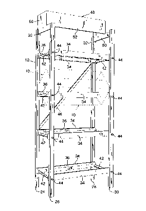
Fig. 1 is a perspective view of the herein described
display rack assembly.
Fig. 2 is a view in back elevation of the assembly.
Fig. 3 is a view in a side elevation of the assembly.
Fig. 4 is a top plan view of the assembly.
Fig. 5 is an enlarged fragmentary sectional view taken
along line 5-5 of Fig. 2.
Fig. 6 is a fragmentary, detail view looking in the
direction of the arrows of line 6-6 of Fig. 3.
Fig. 7 is a fragmentary, detail view looking in the
direction of the arrows of line 7-7 of Fig. 2.

`` ` ~16~21
DESCRIPTION OF A PREFERRED EMBODIMENT OF THE INVENTION
As indicated above, the present invention comprises the
combination of a box, indicated generally at 10, and a rack
structure, indicated generally at 12, for displaying the box
in such a manner as to display the contents thereof and make
the contents easily available for dispensing.
In the illustrated form of the invention, Figs. 1 and 5,
box 10 is of the class employed for storing, transporting and
merchandising various articles of commerce, in particular
flower bulbs such as tulip bulbs, lily bulbs and the like. It
is constituted of heavy duty corrugated paper board and
includes a bottom wall 14, a front wall 16, a back wall 18, a
pair of end walls 20 and an openable top closure 22.
The rack support for the box in its illustrated
embodiment includes two pairs of upright support posts 24, 26
and 28, 30, Fig. 1. These are arranged in a spaced,
rectangular arrangement. Each post has in its top an inwardly
facing, centrally located, slot 32.
Associated with the posts are one or more crib structures
arranged for supporting one or more boxes 10 in a display
attitude. To this end there are provided one or more pairs of
horizontally spaced, preferably substantially coplanar, box
support bars 34. Each pair of the bars has opposed beveled
upper surfaces 36 conforming to the contour of the box they
are designed to support.

`: 21~8~21
Also provided are post spacer subassemblies indicated
generally at 38. In addition to their post spacing function,
these elements of the assembly serve the important secondary
function of securing support bars 34 to the support posts.
As shown particularly in Fig. 5, each spacer subassembly
38 comprises a pin 40 mounting a sleeve 42 and terminating in
threaded ends on which are threaded nuts 44, which secure the
bars to the posts.
The spacer subassemblies also serve a third function:
that of providing pin and sleeve type hinges which make
possible shifting the rack structure between expanded use and
collapsed storage positions, as indicated in the dashed
outline of Fig. 2.
Support bars 34 and spacers 38 define a crib having a
central opening contoured and dimensioned to receive one of
boxes 10 in nesting relation and in a canted or cocked
position with its open top 22 facing upwardly in such a manner
as to make its contents readily visible and accessible. Figs.
3 and 5. When thus positioned, the box bottom wall 14 and
its adjacent front wall 16 are in bearing engagement with the
opposed beveled surfaces 36 of support bars 34, thus
stabilizing the box in its use position.
Means are provided for stabilizing rack 12 and for
ensuring that it does not collapse inadvertently if pushed or

2168~21
shoved when in use. As illustrated in Figs. 1 and 2, such
means comprise one or more diagonal braces 46 arranged as
required to provide the desired degree of stability to the
structure. Brace 46 is fabricated from a suitable rigid
material such as wood or metal. As is shown particularly in
Fig. 5, its ends are perforated for reception of the terminal
portions of one of spacer pins 40 thereby mounting the brace
in its operative position. It is to be noted that, as pointed
out above, spacer pins 40 with associated sleeves 42 and nuts
10 44 serve four functions: that of providing a spacer for post
pairs 24, 26 and 28, 30; that of providing a support for bars
34; that of providing a hinge to enable collapsing of the rack
when not in use; and that of mounting brace 46 for rigidifying
the structure when it is in use.
In addition to providing a support for boxes lO, rack 12
also serves the function of supporting a header indicated
generally at 48. This may be inscribed or printed with
advertising information and pictorial representations to
attract the customer to the display and assist him in making
20 his selection.
As illustrated particularly in Fig. 1, the header 48
comprises a flat sheet of cardboard or corrugated box board.
The sheet is divided, as by scoring and folding, to provide a
pair of end panels 50 and a central panel 52. End panels 50
25 are contoured in such a manner as to provide edge portions

2168~21
which are insertable in slots 32 in the upper ends of the
supporting posts. There thus is provided a simple means for
mounting the header, supporting it in a stable condition
during use, and enabling its ready removal at a later date for
storage or discard, as the case may be.
OPERATION
The manner of use of the herein described display rack
assembly is as follows:
Assuming that the rack is in its collapsed, storage
condition, it first is expanded to its use condition of Fig.
1. Brace 46 is put in place to secure the rack against
inadvertent collapse.
The top panels 22 of boxes 10 are opened to display the
contents. The boxes then are placed in the cribs provided by
bars 34 and spacer subassemblies 38 in the canted manner
illustrated in Fig. 5. In this position, the contents of the
boxes are readily visible and readily available for sampling
or dispensing.
Header 48 with advertising indicia printed thereon then
is put in position at the top of the rack, completing the
erection of the display. After its term of use has expired,
the display may be dismantled by reversing the foregoing
procedure.
Having thus described in detail a preferred embodiment of
the invention, it will be apparent to those skilled in the art

`~ ` 216~62~
that various physical changes may be made without altering the
inventive concepts and principles embodied. The present
embodiments therefore are to be considered as illustrative and
not restrictive, the scope of the invention being indicated by
the appended claims.
I claim:

Representative Drawing
A single figure which represents the drawing illustrating the invention.
Administrative Status

2024-08-01:As part of the Next Generation Patents (NGP) transition, the Canadian Patents Database (CPD) now contains a more detailed Event History, which replicates the Event Log of our new back-office solution.

Please note that "Inactive:" events refers to events no longer in use in our new back-office solution.

For a clearer understanding of the status of the application/patent presented on this page, the site Disclaimer , as well as the definitions for Patent , Event History , Maintenance Fee  and Payment History  should be consulted.

Event History

Description Date
Inactive: IPC from MCD 2006-03-12
Time Limit for Reversal Expired 2002-02-01
Letter Sent 2001-02-01
Grant by Issuance 1999-01-19
Inactive: Final fee received 1998-09-02
Pre-grant 1998-09-02
Notice of Allowance is Issued 1998-07-02
Letter Sent 1998-07-02
Inactive: Status info is complete as of Log entry date 1998-06-23
Inactive: Application prosecuted on TS as of Log entry date 1998-06-23
Inactive: Approved for allowance (AFA) 1998-05-27
Application Published (Open to Public Inspection) 1997-01-15
All Requirements for Examination Determined Compliant 1996-02-01
Request for Examination Requirements Determined Compliant 1996-02-01

Abandonment History

There is no abandonment history.

Maintenance Fee

The last payment was received on 1998-12-31

Note : If the full payment has not been received on or before the date indicated, a further fee may be required which may be one of the following

  • the reinstatement fee;
  • the late payment fee; or
  • additional fee to reverse deemed expiry.

Patent fees are adjusted on the 1st of January every year. The amounts above are the current amounts if received by December 31 of the current year.
Please refer to the CIPO Patent Fees web page to see all current fee amounts.

Fee History

Fee Type Anniversary Year Due Date Paid Date
MF (application, 2nd anniv.) - standard 02 1998-02-02 1998-01-06
Final fee - standard 1998-09-02
MF (application, 3rd anniv.) - standard 03 1999-02-01 1998-12-31
MF (patent, 4th anniv.) - standard 2000-02-01 2000-02-01
Owners on Record

Note: Records showing the ownership history in alphabetical order.

Current Owners on Record
VAN BLOEM, INC.
Past Owners on Record
BRUCE B. KAPTEYN
Past Owners that do not appear in the "Owners on Record" listing will appear in other documentation within the application.
Documents

To view selected files, please enter reCAPTCHA code :


To view images, click a link in the Document Description column. To download the documents, select one or more checkboxes in the first column and then click the "Download Selected in PDF format (Zip Archive)" or the "Download Selected as Single PDF" button.

List of published and non-published patent-specific documents on the CPD .

If you have any difficulty accessing content, you can call the Client Service Centre at 1-866-997-1936 or send them an e-mail at CIPO Client Service Centre.


Document
Description 
Date
(yyyy-mm-dd) 
Number of pages   Size of Image (KB) 
Claims 1998-05-12 2 66
Description 1996-05-28 7 218
Abstract 1996-05-28 1 14
Claims 1996-05-28 3 83
Drawings 1996-05-28 3 89
Representative drawing 1999-01-06 1 15
Representative drawing 1997-07-17 1 29
Reminder of maintenance fee due 1997-10-04 1 111
Commissioner's Notice - Application Found Allowable 1998-07-01 1 164
Maintenance Fee Notice 2001-02-28 1 176
Fees 2000-01-31 1 28
Fees 1998-12-30 1 33
Correspondence 1998-09-01 1 27
Fees 1998-01-05 1 37
Prosecution correspondence 1998-04-20 2 77
Examiner Requisition 1998-04-20 2 72