Language selection

Search

Patent 2168898 Summary

Third-party information liability

Some of the information on this Web page has been provided by external sources. The Government of Canada is not responsible for the accuracy, reliability or currency of the information supplied by external sources. Users wishing to rely upon this information should consult directly with the source of the information. Content provided by external sources is not subject to official languages, privacy and accessibility requirements.

Claims and Abstract availability

Any discrepancies in the text and image of the Claims and Abstract are due to differing posting times. Text of the Claims and Abstract are posted:

  • At the time the application is open to public inspection;
  • At the time of issue of the patent (grant).
(12) Patent: (11) CA 2168898
(54) English Title: REMOVING IMPURITIES FROM PULVERIZED OR CHIPPED MATERIAL
(54) French Title: ELIMINER LES IMPURETES DES MATERIAUX PULVERISES OU DECHIQUETES
Status: Term Expired - Post Grant Beyond Limit
Bibliographic Data
(51) International Patent Classification (IPC):
  • B07B 13/04 (2006.01)
  • B07B 1/14 (2006.01)
  • B27N 1/00 (2006.01)
  • D21B 1/02 (2006.01)
(72) Inventors :
  • LAATIKAINEN, AARNE (Finland)
(73) Owners :
  • SUNDS DEFIBRATOR LOVIISA OY
  • DIEFFENBACHER PANELBOARD OY
(71) Applicants :
  • SUNDS DEFIBRATOR LOVIISA OY (Finland)
  • DIEFFENBACHER PANELBOARD OY (Finland)
(74) Agent: MARKS & CLERK
(74) Associate agent:
(45) Issued: 2006-05-16
(22) Filed Date: 1996-02-06
(41) Open to Public Inspection: 1996-08-16
Examination requested: 2003-01-06
Availability of licence: N/A
Dedicated to the Public: N/A
(25) Language of filing: English

Patent Cooperation Treaty (PCT): No

(30) Application Priority Data:
Application No. Country/Territory Date
950680 (Finland) 1995-02-15

Abstracts

English Abstract

The invention relates to a method and apparatus for screening pulverized or chip material, such as fibers or wood chips, free from impurities. The material to be screened is fed onto a roil set formed by a number of adjacent, essentially parallel rolls (1) and is brought to an advantageous movement with the help of said rolls (1), whereby material particles of highest density drift downward closest to the surfaces of the rolls and that the material fraction closest to the roll surfaces can escape the rolls via a gap (B) a width essentially larger than the gap width (A) of the preceding roll pairs.


French Abstract

L'invention concerne une méthode et un appareil pour tamiser des matériaux pulvérisés ou déchiquetés, tels que des fibres ou des copeaux de bois, pour les rendre libres de toute impureté. Les matériaux à tamiser sont apportés à un ensemble de rouleaux formé par plusieurs rouleaux adjacents, essentiellement parallèles (1) et sont amenés à un mouvement avantageux à l'aide des dits rouleaux (1), dans lequel les particules de matériau de la densité la plus élevée dérivent vers le bas, au plus près des surfaces des rouleaux et les fractions de matériau les plus proches des surfaces des rouleaux peuvent s'échapper des rouleaux par un espace (B) dont la largeur est essentiellement plus grande que la largeur de l'espace (A) de la paire de rouleaux précédents.

Claims

Note: Claims are shown in the official language in which they were submitted.

7
The embodiments of the present invention in which an
exclusive property or privilege is claimed are defined as
follows:
1. A method of screening pulverized or chip material free
from impurities, in which method the material to be
screened is fed onto a set of rollers formed by a plurality
of adjacent, substantially parallel rollers forming an
initial enrichment section of rollers with gap widths (A)
followed by at least one gap (B) of greater width than the
gap width (A) between preceding roller pairs, and is
brought to a fluid movement of material with the help of
said rollers in a manner such that material particles of
higher density drift downward closest to the surfaces of
the rollers of gap width (A) and lower density particles
are carried above and by the higher density particles,
whereby the higher density material closest to the roller
surfaces and with impurities enriched therein can escape
the rollers via gap (B) and the lower density particles
move over gap (B}.
2. A method as defined in claim 1, in which a major
portion of the material is passed via said gap (B) to
further processing by additional screening or postcleaning.
3. A method as defined in claim 1 or 2, in which fine
particulates with fine impurities enriched therein are
removed via said gap widths (A).
4. A method as defined in claim 1, wherein the material
fraction removed from the set of rollers via said gaps (A)
or said gap (B) is taken to further processing.

8
5. A method as defined in claim 4, wherein the step of
further processing includes additional fractionation.
6. A method as defined in any one of claims 1 to 5,
wherein the pulverized or chip material includes fibers or
wood chips.
7. An apparatus for screening pulverized or chip material
free from impurities, the apparatus comprising a set of
rollers formed by a plurality of adjacent, substantially
parallel rollers forming a number of pairs of rollers with
gap widths (A) followed by two rollers separated by a gap
(B) of greater width than the gap widths (A) between
preceding roller pairs such that fluid movement of material
with the help of said rollers causes material particles of
higher density to drift downward closest to the surfaces of
the rollers and lower density particles to be carried above
and by the higher density particles, whereby the higher
density material closest to the roller surfaces with
impurities enriched therein can escape the rollers via gap
(B) and the lower density particles move over gap (B).
8. Apparatus as defined in claim 7, wherein the inter-
roller gap width (A) is 0.2 - 0.5mm and the gap width (B)
is 1 - 2.5mm.
9. Apparatus as defined in claim 7 or 8, wherein the
inter-roller gap widths in the set of rollers are
individually adjustable.
10. Apparatus as defined in claim 7, 8 or 9, wherein the
rollers are provided with a surface texturing.

Description

Note: Descriptions are shown in the official language in which they were submitted.


CA 02168898 2005-06-27
1
Removing Impurities From Pulverized Or Chipped Material
The present invention relates to a method and apparatus for
screening pulverized or chip material (in particular wood
chip and fiber materials) so that it is relatively free
from impurities. The material to be screened is fed onto a
set of rollers and is brought to a fluid movement with the
help of the rollers in a manner such that material
particles of higher density drift downward closest to the
surfaces of the rollers and lower density particles are
carried above and by the higher density particles, and they
can be separated.
Pulverized and chipped materials comprise, e.g., different
kinds of fibers and wood chips used in the manufacture of
particleboard/fiberboard and similar products. Such boards
are made increasingly from residue materials. Resultingly,
a need arises for removing impurities from the raw material
stock. Typical impurities comprise different minerals,
rocks, sand and similar particulates. In the board
manufacturing process, the content of impurities
significantly affects the wear rate of tools such as
different cutting means employed in the finishing
operations of boards made from residue materials. Hence, a
variety of screening methods has been developed. Known in
the art are arrangements in which mere blowing by air is
used for separating impurities from the raw material. Such
embodiments are handicapped by high specific energy
consumption and dust emissions. Moreover, extremely fine
impurity particulates are not removed in a desired manner
by air blowing, whereby the end result of the screening
operation remains unsatisfactory.

CA 02168898 2005-06-27
2
It is an object of the present invention to provide a
method and apparatus for removing impurities from
pulverized or chip material; the method and apparatus being
free from many of the disadvantages of conventional
techniques.
According to this invention, a method of screening
pulverized or chip material so that it is relatively free
from impurities comprises feeding the material onto a set
of rollers formed by a plurality of adjacent, substantially
parallel rollers. In an initial enrichment section there
are rollers with gap widths, and they are followed by
rollers having at least one gap of greater width than the
gap width between preceding roller pairs. The material is
brought to a fluid movement with the help of those rollers
in a manner such that material particles of higher density
drift downward closest to the surfaces of the rollers and
lower density particles are carried above and by the higher
density particles. Thus the higher density material
closest to the roller surfaces and with impurities enriched
therein can escape the rollers via the wider gap while the
lower density particles move over that gap.
Similarly, apparatus for screening pulverized or chip
material relatively free from impurities comprises a set of
rollers formed by a plurality of adjacent, substantially
parallel rollers forming a number of pairs of rollers with
narrower gap widths followed by rollers separated by a gap
of greater width between preceding roller pairs. Fluid
movement of material with the help of the rollers causes
material particles of higher density to drift downward
closest to the surfaces of the rollers and lower density
particles to be carried above and by the higher density

CA 02168898 2005-06-27
3
particles, whereby the higher density material closest to
the roller surfaces with impurities enriched therein can
escape the rollers via the wider gap and the lower density
particles move over that gap.
The arrangement according to the invention offers a number
of significant benefits. Mechanical screening of impurities
offers a reduction in specific energy consumption with
regard to separation with air blowing alone. The screening
apparatus will become smaller and easy to combine with a
roller set screen, for instance. Furthermore, the material
fractions precleaned or fractionated with the help of the
method according to the invention can be easier and more
effectively handled in further processing by means of,
e.g., other post-screening apparatus.
By arranging the screen roller set to have the narrower
slits between the rollers at the intake end of the
apparatus, it is possible to screen away fines such as silt
that are otherwise extremely difficult or even impossible
to remove by pneumatic means, for instance.
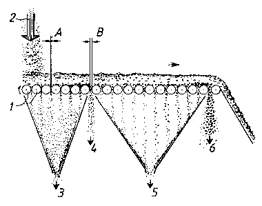
In the following the invention will be explained with the
help of a preferred exemplifying embodiment by making
reference to the appended drawing, in which the screening
process by means of the screen roller set according to the
invention is illustrated diagrammatically.
The screening method according to the invention is based on
the use of a set of rollers (rolls). The material to be
screened is taken and fed by means of conventional feed
elements (not shown) onto the roll set, at its intake end,
advantageously spread in the cross-machine direction

CA 02168898 2005-06-27
4
relative to the travel direction of the chips, essentially
over the entire width of the roll set. The roll set is
formed by a plurality of adjacent, substantially parallel
rolls l, which are arranged to rotate clockwise (arrow)
when viewed at the roll ends as shown in the diagram. The
rolls are spaced from each other to provide gaps,
preferably with individually adjustable widths, for each
pair of adjacent rolls. A feasible adjustment method is
disclosed in FI patent application 922,777. While the rolls
are advantageously aligned in the same plane,~other
arrangements also are possible. For instance, the rolls can
be stepped at increasing heights toward the exit end of the
material.
Typically, the width A of the interroll gap at the intake
end of the roll set is 0.2 - 0.5 mm. These leading rolls
are followed by a gap having a width B wider than the gap
width A of the leading rolls. Typically, the gap width B is
in the order of 1 - 2.5 mm. The width of the interroll gaps
as well as their mutual staging are parameters that
obviously are dependent on the material being screened. The
rolls 1 may be provided with a surface texturing such as
different kinds of grooves, for instance. The depth of such
texturing may be varied, e.g., typically so that the
grooves on the exit end rolls are deeper than in the intake
end rolls.
Onto the intake end of the roll set is fed in the manner
indicated by arrow 2 such raw material, e.g., residues that
contain fibers and mixed therein impurities like minerals,
e.g., sand and rocks. The rotating rolls 1 then transfer
the material forward on the rolls and impart the material
blanket resting on the rolls to undergo an advantageous

CA 02168898 2005-06-27
movement such as an almost fluidized-bed state, whereby the
material particulates of highest density drift downward
closest to roll surfaces. Only the finest particulates 3
can pass through the interroll gaps A of the roll set 1.
5 The fraction of fines 3 passing through the gaps A will be
enriched with the fine particulates accumulated close to
the surfaces of the rolls. The other fractions of the
material including coarser impurities running closest to
the surfaces of the rolls will be moved forward along the
roll set. As the material blanket reaches the next wider
gap B, the next fraction of impurities 4 closest to the
rolls can here escape the rolls by passing through the gap
B. Simultaneously, the major fraction is transferred over
the gap B. Now, the major fraction of the material to be
screened is cleaned relatively free from impurities. Such
clean material fraction can be transferred to further
processing. The roll set may comprise a plurality of gaps,
each wider than the preceding gap to perform in the above-
described manner, whereby the screening process is
iteratively repeated at each gap.
In the apparatus shown in the diagram, the first roll set
is followed by a second roll set in which the particulate
matter is screened via the interroll gaps into material
2~ fractions indicated by arrow 5, while the impurities
indicated by arrow 6 are screened away through the exit end
gap and removed in same manner as described above for the
roll set of wider roll gaps.
Means such as chutes are advantageously arranged under the
rolls for taking the screened material fractions to further
processing.

CA 02168898 2005-06-27
6
The method according to the invention may be easily adapted
and the assembly according to the invention readily
connected to existing roll set screen equipment. The
invention finds important use in chipboard manufacture when
combined with, e.g., the screening step following the
drying step of chips.
To those versed in the art it will be obvious that the
invention is not limited by the exemplifying embodiments
described above, but rather, may be varied within the scope
and spirit of the accompanying claims.

Representative Drawing
A single figure which represents the drawing illustrating the invention.
Administrative Status

2024-08-01:As part of the Next Generation Patents (NGP) transition, the Canadian Patents Database (CPD) now contains a more detailed Event History, which replicates the Event Log of our new back-office solution.

Please note that "Inactive:" events refers to events no longer in use in our new back-office solution.

For a clearer understanding of the status of the application/patent presented on this page, the site Disclaimer , as well as the definitions for Patent , Event History , Maintenance Fee  and Payment History  should be consulted.

Event History

Description Date
Inactive: Expired (new Act pat) 2016-02-06
Inactive: Office letter 2012-04-04
Inactive: Reversal of will be deemed expired status 2012-03-28
Letter Sent 2012-02-06
Letter Sent 2009-10-19
Inactive: Correspondence - Transfer 2009-08-27
Grant by Issuance 2006-05-16
Inactive: Cover page published 2006-05-15
Inactive: IPC from MCD 2006-03-12
Pre-grant 2006-02-27
Inactive: Final fee received 2006-02-27
Letter Sent 2005-11-02
Notice of Allowance is Issued 2005-11-02
Inactive: Approved for allowance (AFA) 2005-08-08
Amendment Received - Voluntary Amendment 2005-06-27
Inactive: S.30(2) Rules - Examiner requisition 2004-12-30
Inactive: Status info is complete as of Log entry date 2003-02-21
Letter Sent 2003-02-21
Inactive: Application prosecuted on TS as of Log entry date 2003-02-21
All Requirements for Examination Determined Compliant 2003-01-06
Request for Examination Requirements Determined Compliant 2003-01-06
Application Published (Open to Public Inspection) 1996-08-16

Abandonment History

There is no abandonment history.

Maintenance Fee

The last payment was received on 2006-01-23

Note : If the full payment has not been received on or before the date indicated, a further fee may be required which may be one of the following

  • the reinstatement fee;
  • the late payment fee; or
  • additional fee to reverse deemed expiry.

Please refer to the CIPO Patent Fees web page to see all current fee amounts.

Owners on Record

Note: Records showing the ownership history in alphabetical order.

Current Owners on Record
SUNDS DEFIBRATOR LOVIISA OY
DIEFFENBACHER PANELBOARD OY
Past Owners on Record
AARNE LAATIKAINEN
Past Owners that do not appear in the "Owners on Record" listing will appear in other documentation within the application.
Documents

To view selected files, please enter reCAPTCHA code :


To view images, click a link in the Document Description column. To download the documents, select one or more checkboxes in the first column and then click the "Download Selected in PDF format (Zip Archive)" or the "Download Selected as Single PDF" button.

List of published and non-published patent-specific documents on the CPD .

If you have any difficulty accessing content, you can call the Client Service Centre at 1-866-997-1936 or send them an e-mail at CIPO Client Service Centre.


Document
Description 
Date
(yyyy-mm-dd) 
Number of pages   Size of Image (KB) 
Representative drawing 1998-03-20 1 17
Cover Page 1996-02-06 1 19
Abstract 1996-02-06 1 17
Description 1996-02-06 4 184
Claims 1996-02-06 2 56
Drawings 1996-02-06 1 20
Representative drawing 2004-12-20 1 14
Description 2005-06-27 6 224
Claims 2005-06-27 2 71
Cover Page 2006-05-10 1 44
Reminder of maintenance fee due 1997-10-08 1 111
Reminder - Request for Examination 2002-10-08 1 115
Acknowledgement of Request for Examination 2003-02-21 1 173
Commissioner's Notice - Application Found Allowable 2005-11-02 1 161
Correspondence 2006-02-27 1 32
Correspondence 2012-04-04 1 17