Note: Descriptions are shown in the official language in which they were submitted.
2169109
1 A METHOD AND APPARATUS FOR PRINTING A GRAPHIC ON FABRIC
Background of the Invention
The present invention relates to printing graphics, such as alphanumeric
symbols, designs, logos and other artwork, on fabric. More particularly, the
present
invention relates to printing graphics on fabric using a thermal transfer
printer.
Typically, graphics are printed on fabric using a thermal transfer process. In
such a process a thermal transfer ribbon, including a colorant layer of
pigment dispersed
in a wax, resin or wax-resin vehicle, is used to print the desired graphic
onto a thermally
1 o stable substrate, such as thermal paper, coated with a resin binder. The
printed paper is
then placed print side down on the fabric, and the colorant is transferred to
the fabric in a
press by the application of heat and pressure. The resin binder is also
transferred, and
the resin binds the colorant to the fabric.
Generally, the printed graphic is defined by one or more print areas
15 covered by the colorant and adjacent "white" or non-print areas. However,
since the
entire surface of the thermal paper is coated with the binder, binder
transfers to the fabric
throughout this adjacent, non-print area, as well as in the areas covered by
the colorant.
The binder gives the non-print areas of the fabric an undesirable hand or
texture and
also seals the fabric weave together, which prevents the free passage air and
moisture
z o through the fabric in the non-print areas. Further, the resin binder is
not transparent and
leaves a shadow around the graphic. The resin shadow is particularly
noticeable on
colors other than white. Thus, the above-described method of printing is
generally
limited to use with white fabrics.
According to an alternative process, typically used in most high volume
2 s applications, the thermal transfer is prepared by screen printing or
lithographically
printing a desired graphic onto a thermally stable substrate. Since both
processes
employ inks instead of the pigmented wax or resin compounds described above in
connection with thermal transfer ribbons, the resin binder and its associated
disadvantages are eliminated. However, screen printing and lithographic
printing, are
30 labor intensive processes requiring artwork, ink mixing, color separation,
printing
216 I 09
1 ,reens or color separation films, a UV exposure step, and the use of
emulsions,
developers and other chemicals in addition to the inks. Moreover, the prepared
screens
or films can be use to print single size designs only.
It is, therefore, an object of the invention to provide a method for printing
s graphics on fabric which requires less labor and equipment than screen
printing or
lithographic printing and which does not require the inks and other chemicals
used in
these processes.
It is a further object of the invention to provide a method wherein the
graphic is printed using a thermal printer and the final product is coated
with binder in
only those areas corresponding to the print area of the graphic.
It is yet another object of the invention to provide an apparatus for carrying
out such a process.
Summar)r of the Invention
The present invention meets these objects by providing, in one aspect, a
method for printing a graphic on fabric using a thermal transfer printer
having a first
ribbon including a carrier layer and a layer of binder supported on the
carrier layer, and
a second ribbon including a carrier layer and a layer of a colorant supported
on the
carrier layer. The thermal printer is provided with data defining the graphic
to be printed
2 0 on the fabric, and the printer is activated to print binder with the first
ribbon onto a
thermally stable substrate according to the data. Thus, a print area including
the binder
and an adjacent non-print area without binder are formed on the substrate.
Once the
binder has been deposited on the substrate, the printer is activated to print
colorant with
the second ribbon onto the print area of the substrate according to the data.
In the final
2 5 step of the method, the graphic is printed on the fabric by thermally
transferring the
binder and colorant from the substrate to the fabric and adhering the colorant
to the
fabric with the binder.
In the preferred embodiment of this aspect of the invention, the printer has a
single ribbon including a carrier layer, a colorant layer supported on the
carrier layer,
216910 9
3
~d a binder layer overlying the colorant layer. Accordingly, the steps of
printing the
binder and printing the colorant are performed simultaneously using the single
ribbon.
According to a second aspect, the invention provides a method for printing
a graphic directly on fabric in which the steps of printing the binder and
colorant on a
thermally stable substrate and then thermally transferring the binder and
colorant to the
fabric are eliminated. The method taught by this aspect of the invention
utilizes a thermal
transfer printer having a first ribbon including a carrier layer and a layer
of colorant
supported on the carrier layer, and a second ribbon including a carrier layer
and layer of
binder supported on the carrier layer. The printer is provided with data
defining the
1 o graphic to be printed on the fabric, and the printer is activated to print
colorant with the
first ribbon onto the fabric according to the data. Thus, a print area
including the colorant
and an adjacent non-print area absent any colorant are formed on the fabric.
The printer
is then activated to print binder with the second ribbon onto the print area
of the fabric
according to the data to bind the colorant to the fabric.
1 s In the preferred embodiment of this second aspect of the invention, the
thermal printer has a single ribbon including a carrier layer, a binder layer
supported on
the carrier layer, and a colorant layer overlying the binder layer.
Accordingly, the steps of
printing the binder and printing the colorant are performed simultaneously
using the
single ribbon.
2 o The invention is useful for printing graphics, either directly or by means
of a
transfer, on a wide variety of fabrics including cotton, polyester, cotton-
polyester blends,
wool, nylon, silk, rayon and rayon-polyester blends. The only limitation with
respect to
the fabric is that the fabric must have sufficient thermal stability to
withstand either the
heat and pressure of the transfer press, or the heat of the thermal printer
where the
25 graphic is printed directly on the fabric. Moreover, since binder is
applied only to the
print area of the fabric according to the invention and the resin shadow
typical of the prior
art is eliminated, the invention can be used with fabric of any color.
2169 ~9
4
Brief Description Of The Drawings
Fig. 1 is a schematic diagram illustrating a system for printing graphics on
fabric according to the present invention.
Fig. 2 is a schematic side view of a thermal printer for use in the system
shown in Fig. 1.
Fig. 3 is a cross-section of a transfer ribbon for use in the printer
illustrated
in Fig. 2.
Fig. 4 is a cross-section of another transfer ribbon for use in the printer
illustrated in Fig. 2.
1 o Fig. 5(a) is a cross-section of a transfer ribbon for use with an
alternative
embodiment of the invention.
Fig. 5(b) is a cross-section of a second transfer ribbon for use the
alternative embodiment of the invention.
Detailed Description of the Invention
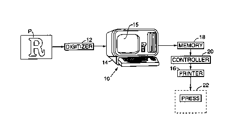
Figure 1 illustrates a microprocessor based system, generally designated
10, having apparatus for printing graphics on fabric. To print a graphic, such
as the
graphic P, the system 10 includes a digitizer 12 or other data input device
which supplies
a computer 14 with machine readable data defining the graphic to be printed.
From the
2o data defining the graphic, the computer 14 generates a printing program for
operating a
thermal printer 16 that prints the graphic on a thermally stable substrate.
The program is
stored in memory 18, and when the graphic is to be printed, a controller 20
reads the
program and operates the printer. Once the graphic has been printed on the
substrate, it
is transferred from the substrate to the fabric in a thermal transfer step
carried out in
2 5 press 22.
A thermal printer useful in practicing the invention is illustrated
schematically in Fig. 2. The printer, generally designated 16, includes a
roller platen 24
over which the thermally stable substrate S passes relative to a thermal print
head 26.
The substrate S is supplied in sheet or strip form and may be any thermally
stable
3 o medium known to those skilled in the art for use in thermal transfer
printing processes.
21~g109
However, in the illustrated embodiment of the invention, the substrate S is
either a
thermal paper available from, for example Hobart-Macintosh, Inc., Elk Grove
Villiage, IL,
under the trade designation "SOFTtrans", coated with a paraffin-based wax, or
a
polyethylene coated paper available from, for example, Lamart Corp., Clifton,
NJ.
As the thermal paper passes over the platen 24, the print head is pressed
downwardly onto the paper and generally establishes a linear zone of contact
between
the paper and the platen. A cassette 28 supplies a thermal transfer ribbon 30
which
carriers a colorant and a binder. The ribbon 30 extends from a supply roll 32,
between
the print head 26 and the platen 24, to a take-up roll 34 of the cassette.
Thus, as the print
1 o head 26 presses down on the platen 24 with the thermal paper and ribbon 30
interposed
therebetween, the colorant and binder carried by the ribbon are transferred to
the paper
according to the data defining the graphic.
Referring now to Fig. 3, in the preferred embodim>snt of the invention the
ribbon 30 includes a carrier layer 36, a layer of colorant 38 supported on the
carrier layer
and a layer of binder 40 supported on the colorant layer. The layer 36 may
comprise any
material typically employed as a carrier in prior art thermal transfer
ribbons. In most
ribbons the carrier is formed from polyester and that is the material which
comprises the
carrier in the illustrated embodiment.
As mentioned above, the colorant layer 38 comprises pigment dispersed in
a wax, a resin or wax-resin vehicle. Typical wax vehicles include, for
example, carnauba,
montan, beeswax, ceresine, haze, candelila, spermaceti, paraffin and
microcrystalline
wax. Resin vehicles used in formulating the colorant layer include, for
example, low
molecular weight polyethylene and polystyrene, vinyl polystearate, petroleum
resins,
polyamide resins, acrylic resins, PVC, PVA and ethylene-vinyl acetate
copolymers.
Mixtures of these and other waxes and resins well-known to those skilled in
the art are
A
2169 I 09
1 ~ ~so used to formulate the colorant layer. The colorant layer may further
include
additional compounds such a softening agents and plasticizers.
For multi-color graphics, the ribbon may include only a single pigment in
the colorant layer, in which case the cassette 28 must be changed as each
color of the
graphic is printed sequentially. Alternatively, the ribbon 30 may be
formulated with a
standard CMYK colorant layer set, in which case process color printing can be
carried
out with a single cassette to print the multicolored graphic on thermal paper.
Turning now to the binder for adhering the pigment to the fabric, the layer
comprises a film-forming binder provided on the ribbon 30 in a dissolved or
finely
to dispersed homogeneous state. The binder must exhibit sufficient
printability to be printed
easily and precisely on the thermal paper by the printer 16, and, when
eventually
transferred to the fabric by the heat and pressure generated by the press 22,
the binder
must form a clear, colorless film of uniform thickness which encloses the
pigment and
adheres it to the fibers. Synthetic polymer binders based on acrylic acid and
butadiene
15 and vinyl acetate are preferred. Binders that have been found to be
particularly suitable
include an acrylic colloidal solution available from Johnson Polymer, Racine
WI, under
the trademark JONCRYL 91, an acrylic aqueous solution available from Lawter
International, Inc. under the trade designation HYDRO-REZ 2000, and an acrylic
aqueous solution available from Miles, Inc., Pittsburgh, PA under the trade
designation
2 o Acramin Binder GD.
Since the pigment and its binder are provided on a single ribbon, the
graphic P can be printed on the thermal paper S in a single step for
subsequent transfer
to the appropriate fabric. Furthermore, since the binder 40 is carried by the
ribbon 30 and
is not provided as a coating on the thermal paper, binder is transferred onto
the fabric
2 s according to the data comprising the printing program stored in memory 18.
Thus, the
method of printing taught by the present invention eliminates the
disadvantages of prior
art methods of printing on fabric, wherein the entire surface of the fabric is
coated with
binder, including the non-print areas not covered by the graphic.
In the most preferred embodiment of the invention, the ribbon 30 comprises
3 o a general purpose high speed wax ribbon available from, for example,
Advent
2169 ~ 09
7
1 corporation, Ellington, CT, under the trade designation AD-102HS, coated
with an
acrylic binder. The Advent ribbon includes a base or carrier layer of
polyester having a
thickness of about 4.5 Vim, which supports a pigmented wax ink having a
melting point of
about 70°C and an optical density of about 1.85. The acrylic binder
comprises 90 weight
% "Acramin GD", 10 weight % "Acrafix MA" (Miles, Inc., Pittsburgh, PA), and a
non-ionic
surfactant added at 1 % by weight of the total solution.
Referring now to Fig. 4, a second ribbon 42 is shown for printing a graphic
directly on fabric without the need for a thermal transfer step. According to
this aspect of
the invention, the ribbon 42 includes a polyester carrier layer 44, a layer of
binder 46
1 o supported on the carrier layer, and a colorant layer 48 supported on the
binder layer.
The composition of the layers 44, 46 and 48 are identical to the corresponding
layers
described above with respect to the ribbon 30, except that the positions of
the binder and
colorant layers are reversed on the ribbon 42. By forming the ribbon 42 with
the pigment
in the outermost layer, and supplying the fabric directly to the printer in
place of the
thermal paper as the substrate S, it has been found that the thermal printer
16 can be
used to print pigment and binder directly onto the fabric according to the
data comprising
the printing program. Thus, the step of transferring the graphic from the
thermal paper to
the fabric in the press 22 is entirely eliminated. The only limiting factor
here is that the
fabric must be capable of withstanding the heat generated by the thermal
printer without
2 o degrading.
Whether the ribbon is constructed in the manner described in connection
with ribbon 30 or ribbon 42, it is desirable when using a resin, a wax or a
wax/resin
vehicle for the pigment to include a release layer between the polyester
carrier and the
immediately adjacent layer of either colorant or binder. Any suitable release
agent may
be utilized as long as it provides the release layer with a melting point
which is lower
than the melting point of the colorant. Figs. 5(a) and 5(b~ illustrate ribbons
useful in
carrying out this aspect of the invention. As shown in Fig. 5(a), the ribbon
includes a
carrier layer 52, a release layer 54 supported on the carrier layer, a
colorant layer 56
supported on the release layer, and a binder layer 58 supported on the
colorant layer.
3 o Alternatively, the ribbon 60 shown in Fig. 5(b) includes a carrier layer
62, a release layer
2169109
~ supported on the carrier layer, a binder layer 66 supported on the release
layer, and
a colorant layer 68 supported on the binder layer.
In addition to the above-described methods for printing a graphic on fabric,
the invention encompasses a method wherein a thermal printer, such as the
printer
s illustrated in Fig. 2, and an associated ribbon are used to print colorant,
according to
data defining the graphic to be printed, onto a thermally stable substrate,
such as thermal
paper, coated with a film of resin binder. A computer-controlled plotter
having a cutting
blade and provided with machine-readable data defining the graphic is then
used to cut
around the graphic after which those portions of the resin film which are not
covered
1o with colorant are removed. Thus, according to this method, the thermal
transfer
comprises the thermally stable substrate covered with resin and colorant only
in the print
area corresponding to the graphic.
In yet another embodiment of the invention, a thermally stable substrate,
such as thermal paper, is coated with resin binder. A barrier layer which
prevents
15 release of the binder from the substrate in the transfer press is then
printed onto the non-
print areas of the substrate. Using a standard ribbon, colorant is then
printed onto the
print area of the substrate according to data defining the graphic to be
printed.
Accordingly, when the graphic is transferred to the fabric in the transfer
press, binder is
transferred to the fabric in the print area only.
2 o In a modification of the above-described method, a dry resin is coated
onto
the thermally stable substrate. The resin forms one part of a two-part binder
system
which also includes a microencapsulated activator for the resin dispersed in
the colorant
layer carried by the ribbon. After the printer applies colorant to the
substrate according to
data defining the graphic to be printed, the microcapsules are ruptured by the
pressure
2 5 applied in the transfer press, and the activator is released into the
resin. Accordingly,
only the print area of the substrate, i.e., that portion of the resin coated
substrate which is
covered by the colorant, is made tacky by the activator. Of course, the
activator does not
have to be incorporated into the colorant layer, but instead could comprise
either a
separate layer on the same ribbon carrying the colorant or on a second ribbon
used in a
3 o second printing operation.