Language selection

Search

Patent 2169581 Summary

Third-party information liability

Some of the information on this Web page has been provided by external sources. The Government of Canada is not responsible for the accuracy, reliability or currency of the information supplied by external sources. Users wishing to rely upon this information should consult directly with the source of the information. Content provided by external sources is not subject to official languages, privacy and accessibility requirements.

Claims and Abstract availability

Any discrepancies in the text and image of the Claims and Abstract are due to differing posting times. Text of the Claims and Abstract are posted:

  • At the time the application is open to public inspection;
  • At the time of issue of the patent (grant).
(12) Patent: (11) CA 2169581
(54) English Title: FLUORESCENT LAMP WITH END OF LIFE ARC QUENCHING STRUCTURE
(54) French Title: LAMPE FLUORESCENTE AVEC STRUCTURE D'EXTINCTION D'ARC EN FIN DE DUREE DE VIE
Status: Expired and beyond the Period of Reversal
Bibliographic Data
(51) International Patent Classification (IPC):
  • H01J 61/42 (2006.01)
  • H01J 61/02 (2006.01)
  • H01J 61/24 (2006.01)
  • H01J 61/30 (2006.01)
  • H01J 61/56 (2006.01)
  • H01J 61/70 (2006.01)
(72) Inventors :
  • SHAFFER, JOHN W. (United States of America)
(73) Owners :
  • OSRAM SYLVANIA INC.
(71) Applicants :
  • OSRAM SYLVANIA INC. (United States of America)
(74) Agent: R. WILLIAM WRAY & ASSOCIATES
(74) Associate agent:
(45) Issued: 2006-11-14
(22) Filed Date: 1996-02-15
(41) Open to Public Inspection: 1996-08-18
Examination requested: 2003-02-12
Availability of licence: N/A
Dedicated to the Public: N/A
(25) Language of filing: English

Patent Cooperation Treaty (PCT): No

(30) Application Priority Data:
Application No. Country/Territory Date
08/389,995 (United States of America) 1995-02-17

Abstracts

English Abstract

A fluorescent lamp comprises a glass tube, an electrode at each end of the tube, a pair of lead wires extending through each sealed end of the tube and joined to one of the electrodes, and a deposit of metal hydride-containing paste disposed in the tube and having a decomposition temperature higher than temperatures within the tube during normal operation of the lamp.


French Abstract

Lampe fluorescente comprenant un tube de verre, une électrode à chaque extrémité du tube, une paire de fils traversant chacune des extrémités du tube fermées hermétiquement et sont reliés à une des électrodes, et une capsule qui contient une pâte d'hydrure métallique disposée dans le tube et dont la température de décomposition est plus élevée que les températures dans le tube lors du fonctionnement normal de la lampe.

Claims

Note: Claims are shown in the official language in which they were submitted.

-9-
1. A fluorescent lamp comprising:
a glass tube;
an electrode at each end of said tube; each of said
electrodes comprising a pair of lead wires extending through
a sealed end of said tube and joined to a coil; and
a deposit of metal hydride-containing paste disposed in
said tube and having a decomposition temperature higher than
temperatures within said tube during normal operation of
said lamp.
2. The fluorescent lamp in accordance with claim 1 wherein
said deposit is disposed on each lead wire of each of said
pairs of lead wires.
3. The fluorescent lamp in accordance with claim 2 wherein
said deposit is disposed on said lead wires at a lead wire-
glass seal interface.
4. The fluorescent lamp in accordance with claim 1 wherein
a glass bead is disposed on each pair of lead wires and said
deposit is disposed on said glass bead.

-10-
5. The fluorescent lamp in accordance with claim 4 wherein
said deposit is disposed on said glass bead at the juncture
of said glass bead and said lead wires extending therefrom.
6. The fluorescent lamp in accordance with claim 1 wherein
said metal hydride contained in said paste is a selected one
from a group consisting of titanium, zirconium, hafnium, a
titanium-zirconium alloy, a titanium hafnium alloy, and a
zirconium-hafnium alloy.
7. The fluorescent lamp in accordance with claim 1 wherein
said metal hydride comprises an alloy consisting of a
selected one from a group consisting of titanium, zirconium,
and hafnium, and a selected one from a group consisting of
cobalt, iron, nickel, manganese, and lanthanum.
8. The fluorescent lamp in accordance with claim 1 wherein
said metal hydride comprises titanium hydride.
9. The fluorescent lamp in accordance with claim 8 wherein
said paste comprises 40 parts by weight of said titanium
hydride and 60 parts by weight of colloidal alumina
suspension in water, said titanium hydride being in finely
powdered form.

Description

Note: Descriptions are shown in the official language in which they were submitted.


94-1-546 -1- PATENT APPLICATION
FLUORESCENT LAMP WITH END OF LIFE ARC QUENCHING STRUCTURE
BACKGROUND OF THE INVENTION
1. Field of the Invention
The invention relates to fluorescent lamps, and is
directed more particularly to a fluorescent lamp having
therein means for quenching the arc in the lamp at the end
of lamp life.
2. Description of the Prior Art
Fluorescent lamps are increasingly being used with
electronic ballasts that operate the lamp at high
frequencies. Often such ballasts are of the "instant start"
type wherein the open circuit voltage is sufficiently high
to ignite the lamp directly, without the need for a separate
cathode heating current.
The end of lamp life occurs when one of the electrodes
is depleted of its emissive coating. At power line
frequencies and with low open circuit voltage ballasts, the
lamp arc is passively extinguished when the first electrode
fails. However, in the case of electronic instant start
ballasts, the lamp arc does not necessarily extinguish when
the first electrode fails. The open circuit voltage
provided by instant start ballasts is sufficiently high to

94-1-546 -2- PATENT APPLICATION
cause the lamp to continue to operate in a "cold cathode"
mode. During cold cathode operation, the cathode voltage
rises from around 12 volts to 50 volts, or higher.
Referring to FIGS. 1 and 2, in a lamp 2 having electrodes 4,
6 at either end of a glass envelope 8, respectively, upon
failure of the first electrode 6, ion bombardment heats the
tungsten coil 10, lead wires 12, 14, and any other metallic
structures within the glass envelope 8. The heating of the
metallic components is to such a high temperature that the
components provide sufficient thermionic and secondary
electron emission to sustain the arc. Wattage dissipation
in the failed lamp end greatly increases. As a result, the
end of the envelope 8 heats far above its normal operating
temperature. The lead wires 12, 14 within the envelope 8
can become molten and melt through the envelope and/or cause
the envelope to crack and sometimes break upon removal of
the lamp from a fixture. The excessive heating of the lamp
end can also cause damage to a socket or lamp fixture in
which the lamp is mounted, or melting of a plastic lamp
base.
To alleviate the problem, instant start electronic
ballasts have been designed with additional circuitry to
sense a rise in lamp voltage, or other events occurring upon
cathode depletion, and shut down the system. However, such

94-1-546 -3- PATENT APPLICATION
additional electronic components significantly increase the
cost of the ballast. Further, many ballasts which do not .
include such a feature already exist in present lamp
installations.
Accordingly, there exists a need for a fluorescent lamp
which self-contains means for arc shut-down at the end of
life of the lamp, which shut-down means does not include or
require additional circuitry or electronic components.
SUMMARY OF THE INVENTION
An object of the invention is, therefore, to provide a
fluorescent lamp having means therein for causing arc shut-
down at the end of lamp life.
A further object of the invention is to provide a
fluorescent lamp having such means for arc shut-down wherein
the shut-down means requires no additional circuitry or
electronic components.
With the above and other objects in view, as will
hereinafter appear, a feature of the invention is the
provision of a fluorescent lamp comprising a glass tube, an
electrode at each end of the tube, each of the electrodes
comprising a pair of lead wires extending through a sealed
end of the tube and joined to a coil, and a deposit of metal
hydride-containing paste disposed in the tube and having a

94-1-546 -4- PATENT APPLICATION
decomposition temperature higher than temperatures within
the tube during normal operation of the lamp.
The above and other features of the invention,
including various novel details of construction and
combination of parts, will now be more particularly
described with reference to the accompanying drawings and
pointed out in the claims. It will be understood that the
particular devices embodying the invention are shown by way
of illustration only and not as limitations of the
invention. The principles and features of this invention
may be employed in various and numerous embodiments without
departing from the scope of the invention.
BRIEF DESCRIPTION OF THE DRAWINGS
Reference is made to the accompanying drawings in which
is shown an illustrative embodiment of the invention, from
which its novel features and advantages will be apparent.
In the drawings:
FIG. 1 is a side elevational view of a prior art
fluorescent lamp;
FIG. 2 is an enlarged diagrammatic view of an end
portion of the lamp of FIG. 1;
FIG. 3 is similar to FIG. 2, but shows one form of
fluorescent lamp illustrative of an embodiment of the

94-1-546 -5- PATENT APPLICATION
invention; and
FIG. 4 is similar to FIG. 3, but shows another form of
fluorescent lamp illustrative of an alternative embodiment
of the invention.
DESCRIPTION OF THE PREFERRED EMBODIMENTS
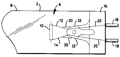
Referring to FIG. 3, there is shown a fluorescent lamp
2 comprising a glass tube 8. An electrode 4, 6, (one shown
in FIG. 3) is disposed at each end of the tube 8. A pair of
lead wires 12, 14 extend through each sealed end of the tube
and are joined to a coil 10 to form the electrodes. A
deposit 30 of metal hydride-containing paste is disposed in
the tube 8 and is provided with a decomposition temperature
higher than temperatures within the tube 8 during normal
operation of the lamp. During normal lamp operation, the
temperature of the paste is preferably maintained at about
150 °C or less. It will be seen that the electrode 6 is
similar to that shown in FIG. 2, but has disposed on each of
the lead wires 12, 14 the metal hydride-containing deposit
30. The deposit 30 preferably is joined to the lead wires
12, 14 at each end of the tube 8 at a point at which the
lead wires 12, 14 emerge from a glass seal 32, that is, at
the lead wire-glass seal interface.
In operation, at the end of the lamp life, caused by

94-1-546 -6- PATENT APPLICATION
depletion of the cathode coating at one end of the lamp, the
coil 10 in that end of the lamp rises to a temperature much
higher than its normal operating temperature and is
eventually burned off. The arc then attaches to a lead wire
12 or 14 and raises the temperature of that wire. Heat
conducted down the wire thermally decomposes the metal
hydride-containing paste deposit 30, and hydrogen is
released within the lamp. During this period, the
temperature of the paste reaches 650 °C or higher. The
presence of hydrogen in the tube 8 raises the voltage
required to sustain the discharge well above that provided
by instant start ballasts, causing the lamp to go out
passively, without significant end heating or glass
cracking. The hydrogen release occurs rapidly enough to
prevent damage to a fixture retaining the affected lamp.
The quantity of hydrogen released, typically about one Torr-
liter from a five milligram deposit, is sufficient to quench
the arc in larger fluorescent lamps.
A preferred embodiment of paste is formulated by mixing
40 parts by weight of finely powdered titanium hydride and
60 parts by weight of colloidal alumina suspension in water.
A deposit of this paste, which, when dried, weighs about
five milligrams, is applied to the base of each lead wire
12, 14 where the lead wire emerges from the glass seal 32.

94-1-546 -7- PATENT APPLICATION
Alternative paste embodiments may be used, including
binders other than colloidal alumina. ~ Preferably, the
binder is inorganic and not subject to outgassing once
dried, such as, for example, montmorillonite clays and
various silicates.
Referring to FIG. 4, there is illustrated an electrode
configuration wherein a glass bead 40 is fixed on the two
lead wires 12, 14 and the deposit 30 preferably is disposed
on the surface of the glass bead nearest the coil 10, though
the deposit may be applied to the sides or surface most
removed from the coil.
The preferred metal hydride is titanium hydride,
TiHl,~. The metal hydride can be selected from a group
including titanium, zirconium, hafnium, alloys of these
metals with one another, and alloys of these metals with
other metals such as cobalt, iron, nickel, manganese,
lanthanum, or combinations of these other metals.
There is thus provided a fluorescent lamp having means
therein for causing shut-down at the end of lamp life, which
means requires no additional circuitry or electronic
components. The costs associated with the shut-down means
are trivial and much lower than the cost of providing a
shut-down circuit in the ballast,~even though the ballast
may survive several lamp lives.

94-1-546 -8- PATENT APPLICATION
It is to be understood that the present invention is by
no means limited to the particular constructions herein
disclosed and/or shown in the drawings, but also comprises
any modifications or equivalents within the scope of the
claims.
Having thus described my invention, what I claim as new
and desire to secure by Letters Patent of the United States
is:

Representative Drawing
A single figure which represents the drawing illustrating the invention.
Administrative Status

2024-08-01:As part of the Next Generation Patents (NGP) transition, the Canadian Patents Database (CPD) now contains a more detailed Event History, which replicates the Event Log of our new back-office solution.

Please note that "Inactive:" events refers to events no longer in use in our new back-office solution.

For a clearer understanding of the status of the application/patent presented on this page, the site Disclaimer , as well as the definitions for Patent , Event History , Maintenance Fee  and Payment History  should be consulted.

Event History

Description Date
Time Limit for Reversal Expired 2013-02-15
Letter Sent 2012-02-15
Letter Sent 2011-05-19
Inactive: Adhoc Request Documented 2010-05-20
Inactive: Office letter 2010-05-18
Appointment of Agent Request 2010-03-09
Revocation of Agent Request 2010-03-09
Grant by Issuance 2006-11-14
Inactive: Cover page published 2006-11-13
Pre-grant 2006-08-30
Inactive: Final fee received 2006-08-30
Inactive: IPC from MCD 2006-03-12
Letter Sent 2006-03-06
Notice of Allowance is Issued 2006-03-06
Inactive: IPC assigned 2006-03-06
Inactive: Approved for allowance (AFA) 2006-02-24
Amendment Received - Voluntary Amendment 2005-08-09
Inactive: S.30(2) Rules - Examiner requisition 2005-02-09
Inactive: S.29 Rules - Examiner requisition 2005-02-09
Inactive: Application prosecuted on TS as of Log entry date 2003-03-28
Letter Sent 2003-03-28
Inactive: Status info is complete as of Log entry date 2003-03-28
All Requirements for Examination Determined Compliant 2003-02-12
Request for Examination Requirements Determined Compliant 2003-02-12
Application Published (Open to Public Inspection) 1996-08-18

Abandonment History

There is no abandonment history.

Maintenance Fee

The last payment was received on 2006-02-13

Note : If the full payment has not been received on or before the date indicated, a further fee may be required which may be one of the following

  • the reinstatement fee;
  • the late payment fee; or
  • additional fee to reverse deemed expiry.

Patent fees are adjusted on the 1st of January every year. The amounts above are the current amounts if received by December 31 of the current year.
Please refer to the CIPO Patent Fees web page to see all current fee amounts.

Owners on Record

Note: Records showing the ownership history in alphabetical order.

Current Owners on Record
OSRAM SYLVANIA INC.
Past Owners on Record
JOHN W. SHAFFER
Past Owners that do not appear in the "Owners on Record" listing will appear in other documentation within the application.
Documents

To view selected files, please enter reCAPTCHA code :


To view images, click a link in the Document Description column. To download the documents, select one or more checkboxes in the first column and then click the "Download Selected in PDF format (Zip Archive)" or the "Download Selected as Single PDF" button.

List of published and non-published patent-specific documents on the CPD .

If you have any difficulty accessing content, you can call the Client Service Centre at 1-866-997-1936 or send them an e-mail at CIPO Client Service Centre.


Document
Description 
Date
(yyyy-mm-dd) 
Number of pages   Size of Image (KB) 
Representative drawing 1998-06-09 1 5
Description 1996-02-14 8 236
Abstract 1996-02-14 1 12
Claims 1996-02-14 3 57
Drawings 1996-02-14 2 25
Representative drawing 2005-02-02 1 7
Claims 2005-08-08 2 51
Reminder of maintenance fee due 1997-10-18 1 111
Reminder - Request for Examination 2002-10-15 1 115
Acknowledgement of Request for Examination 2003-03-27 1 185
Commissioner's Notice - Application Found Allowable 2006-03-05 1 162
Maintenance Fee Notice 2012-03-27 1 172
Fees 2003-02-16 1 39
Fees 2002-02-10 1 38
Fees 2001-02-11 1 34
Fees 1998-02-15 1 44
Fees 1999-02-14 1 41
Fees 2000-02-13 1 38
Fees 2004-02-15 1 34
Fees 2005-02-13 1 31
Fees 2006-02-12 1 40
Correspondence 2006-08-29 1 36
Fees 2007-02-11 1 38
Correspondence 2010-03-08 11 652
Correspondence 2010-05-17 6 411