Note: Descriptions are shown in the official language in which they were submitted.
~ 1 69~q8
-
The present invention relates to a cl~.,,L.il-~ band for tightly clamping a member
to be clamped, e.g., a joint section of a tr~n~mi~ion mPrh~nism, or a radiator pipe of
a car.
Conventionally, in a univel~l joint of a tr~n~mis~ion mech~ni~m of a car, grease
5 is applied to be~ring~ and joint members as a lubricant. The joint members are covered
with a rubber or plastic cover, and the cover is tightly clamped by clamping bands. A
radiator pipe is conn~ted to a radiator and is clamped to a water-tight condition by the
clamping band so as to plcvenL water leakage.
The applicant of the present invention invented a clamping band having a
10 cl~mping ear, which is capable of securely cl~mrin~ without spring back (see Japanese
Patent Kokai Gazette No. 3-163294). The cl~mping band consists of two parts, namely:
a band member and a cl~mrin~ member. The band member is a looped metallic band,
and an Png~ing claw is formed at one end of the band member. The clamping member
has the cl~mping ear in its centre part. One end of the clamping member is spot-welded
15 on the band member, and an engage hole is bored on the other side of the clamping ear.
In the case, for example, of clamping a member to be clamped, e.g., a hose,
which has been connecte~ to a pipe, the member is firstly inserted through the looped
clal~ g band. Then the clamping band is placed on a connecting section of the member
and the pipe. To clamp the member, the clamping ear is coll~lessed in the
20 ~ ;ul~lre~elltial direction of the band member to reduce the diameter thereof. By
re~ucing the tii~m~ter of the band member, the eng~ging claw can be engaged with the
engage hole. By eng~ging the eng~ging claw with the engage hole, the diameter-reduced
2 1 696q8
-
state of the band member can be kept tight even if the el~ticity of the member to be
clamped or the spring back of the coll,pressed çl~mping ear tends to enlarge the diameter
of the band member.
However, since the conventional clamping band consists of the two parts, namely,S the band member and the clamping member,it is difficult correctly to weld the clamping
members at prescribed points on the band members, so that manufacturing efficiency
cannot easily be improved. When the (li~mPter of the band member is reduce~, a step
section is formed in an overlapped part, in which the band member and the clamping
member are ov~lla~ped, on an inner face of the looped band member, and the clamping
member is apt to shift in the transverse direction of the band member. The step section
and the shift can be absorbed if the member to be clamped is made of an elastic m~t~ri~l,
e.g., rubber. In a more recent ilnprove~ent, the joint members of the universal joint
have been covered with a plastic cover, so that grease in the cover will tend to leak at
the step section or at the shift. Further, in the case of clamping, for exarnple, a long
hose, the hose must be inserted through the clamping band, which has been welded to
form into the looped shape, prior to connecting the hose with another member. It is
therefore troublesome to attach the clamping band onto a long member after the long
member is connected.
An object of one aspect of the present invention is to provide a clamping band
having a simple structure, which can be manufactured efficiently.
An object of another aspect of the present invention is to provide a clamping band
which is capable of securely clamping and easily attaching.
~.,
2 1 696~8
By one broad aspect of the present invention, a clamping band is provided
compri~ing: a mPt~llic band having a first end and a second end, the first end of the band
having a form of a Y-shaped fork inclu-ling a pair of fork pieces; a pair of concave
sections formed in each side edge margin of the band, the concave sections being
S capable, ~ ely, of accommodating the fork pieces of the Y-shaped fork when the
band is formed into a loop with the first end being overlapped by the band and with the
concave sections facing inwardly; a clamping ear on the band, the clamping ear having
a gate shape and being disposed at a position on the band overlapping the first end when
the band is formed into the loop, the clamping ear being compressible in the
10 circumferential direction of the loop to permit redu~-ing a diameter of the loop.
By one variant thereof, the concave sections are disposed to accommodate the fork
pieces of the Y-shaped fork when the clamping ear is conlp,c;ssed in the circumferential
direction of the loop such that an inner face of the loop is stepless.
By another variant of this broad aspect of the invention, the top surface of the
15 cl~mpinE ear has a dimple.
By still another variant of this broad aspect of the invention thereof, the clamping
band further inçludes an ~o,n~ging piece which is disposed proximate to the Y-shaped
fork of the band; and a first en~in~ hole for engageably accepting the tong~ging piece,
the first ~ng~ing hole being disposed proximate to the second end of the band, whereby
20 the band is formed into the loop when the first ~-n~ging hole is engaged with the
.o,n~in~ piece.
'~
21 69698
By a variation of such variant, the first eng~ging hole is a long hole which is
elongated in the longitu-~in~l direction of the band, and the Png~ging piece is
longitl~in~lly ~ pl~sP~hle within the first Png~ging hole when the clamping ear is
colllplcssed in the cir-;ulllrelclllial direction of the loop.
By one variation of that variant, the clamping band further includes a second
çng~ging hole which is disposed proAilllale to the first end of the band; and an Png~ging
member which is disposed proximate to the second end of the band for en~ging thesecond eng~ging hole, thereby pcrlllilling the band section to be formed into the loop by
Pn~ging the eng~gin~ member with the first eng~ging the hole on one side of the
eng~ging ear and by Png~ging the eng~ging member with the second çng~gin~ hole on
another side of the clamping ear opposite that side. By a variation of that variation, the
second eng~ging hole is formed by cutting the band to make a cutting hole and embossing
an edge of the cutting hole, and the Pn~ging member is a tongue piece which is
insertable into the second Pn~ging hole. By a second variation of that variant, the
cl~mpin~ band further includes a plurality of eng~gin~ holes which are disposed in the
band incremPnt~lly longitl1-1in~11y displaced from the second eng~ing hole. By a third
variation of that variant, a plurality of eng~gin~ members are disposed on the band
incremPnt~lly longitu-lin~lly displaced from the çng~gin~ member.
By another variant of this broad aspect of the invention, the eng~ging piece is
formed by cutting the band to make a tongue piece, and a bending aid tongue piece is
included to form into an L-shape which is capable of eng~ging with the first çn~ging
hole.
f ~
2 1 696q~ '
-
By still another variant of this broad aspect of the invention, the concave sections
are disposed to accommodate the fork pieces of the Y-shaped fork when the clamping ear
is colllp,essed in the cill;ulllf~erlLial direction of the loop such that an inner face of the
loop is stepless.
S By still another variant, the clamping band further includes an çng~, ing opening
which is disposed proxim~te to the second end of the band; and an en,,~ping member
which is disposed on the band to engage the eng~ging opening and to hold the band in
the loop.
By a second aspect of the present invention, a clamping band is provided
comprising: a band having a first end and a second end, the first end and the second end
dçfining a V-notch in the first end, the band having a length which is suitable for
! ' t forming a loop of a desired open ~ metpr~ wherein an overlap portion of the band is
defined by a portion of the band which is proximate to the second end overlapping a
portion of the band which is proximate to the first end; first and second concavities on
opposing edges of the band facing inwardly with respect to the loop and having sllfficiçnt
depth to accept the first and second ends; and a clamping ea-r disposed on the band at the
overlap portion which is proximate to the second end, the clamping ear having sufficient
~im~ncions when compressed to close the loop to a desired closed diameter when the
second end is fixed at a predetermined position on the band associated with the desired
open ~ met~r.
By a variant of this second aspect of the invention, the clamping band further
includes fixing means for fixing the second end at the predetermined position; the fixing
'~
2 1 69 698
_
means being disposed on the overlap portion between the clamping ear and the second
end.
By one variation of that variant, the fixing means includes first eng~ging meansand second eng~ging means for Png~ging one another, the first eng~ging means being
disposed proximate to the second end and the second eng~ging means being dispose at
a position on the band to m~int~in the loop at the desired open diameter when Png~gin~
the first eng~ging means.
By another variation of that variant, the fixing means includes a dimple which is
disposed plu~ ate to the second end for f~ilit~ting resistance welding of the band at
the dimple to a predetermined portion of the band being overlapped by the dimple to
secure the loop at the desired open diameter. Preferably in such variation, the clamping
band further includes ~lignmpnt means for ~ligning the dimple with the prçdetçrminçd
portion. Still more preferably in such variation, the ~lignmp-nt means includes the feature
that the band defines an opening in the overlap portion which is proximate to the
cl~mI)ing ear and on an opposite side of the clamping ear from that of the second end,
and the band has an eng~ging member which is disposed proximate to the first end for
eng~ing the opening such that the loop is ,,,~ .ined at the desired open diameter with
the dimpled ~ nmPnt with the predetermined portion for resistance welding.
As described above, in aspects of the present invention, since the clamping bandcan consist of only one member, the number of parts and the number of manllfaçtllring
steps can be reduce~l, so that the manufacturing cost of the clamping bands can be
reduced, and manufacturing accuracy can be raised.
't-~ ~
2 1 69698
-
When the cla"lping ear is col"plessed in the circumferential direction, the fork
pieces of the Y-shaped fork are fitted and accommodated in the concave sections, so that
no step section is formed in an inner face of the looped band section. By forming the
flat inner face with no step section, the clamping band is capable of securely and tightly
S cl~..,pill~. Thus, the safety and reliability of the clamping band can be raised.
If the first en~in~ hole is the long hole in which the en~in~ piece is guided
during its movement when the cl~mpin~ ear is colllplessed in the circumferential
direction of the looped band section, a part of an overlapped section of the band section
can be prevented from shifting in the transverse direction.
In the case of forming the band section into the loop by en~in~ the Png~ing
piece with the first ~n~ing hole on one side of the clamping ear and Pn~ing the
en~Ein~ section with the second en~in~ hole on the other side thereof, the clamping
band can be easily attached to, and be det~sh~d from, any members to be clamped.
If a dimple is formed in the top face of the clamping ear, stress in the clamping
ear is absorbed when the clamping ear is col"plessed, so that the clamping ear is able
to resist the spring back and the ~ met~r increment of the band section can be securely
prevented.
If the recess for resistance welding is formed in the vicinity of the second end of
the band section, the resistance welding to fix the second end can be executed effectively.
In the acco",panying drawings,
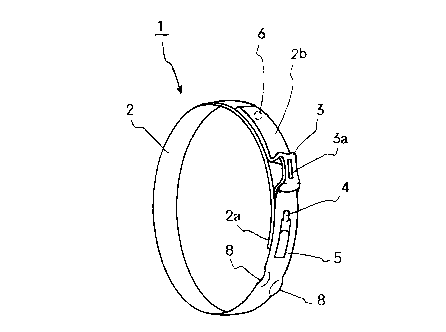
FIG. 1 is a perspective view of a clamping band of a first embodiment of the
present invention;
A
2 1 69698
FIG. 2A is a plan view of a band section of the first embodiment;
FIG. 2B is a front view of the band section;
FIG. 2C is a partial front view of a second end section of the band section in
which a cla"lping ear is formed;
FIG.2D is a front view of the çl~mping band, which has been formed into a loop
shape;
FIG.2Eis a partial plan view showing an eng~ging state of an en~ging piece and
a first engage hole;
FIG. 2F is a partial sectional view showing the eng~ging state of the eng~ging
piece and the first engage hole;
FIG.2G is a partial plan view showing the engage hole of the band section;
FIG.2H is a partial plan view showing the first end section of the band section;FIG.3A is a perspective view of the clamping band, which has been formed into
a loop shape;
FIG. 3B is a perspective view of the clamping band whose clamping ear is
co,l,p,essed in the circumferential direction of the band section;
FIG. 4 is a front view of the clamping band whose clamping ear is colllplessed
in the circumferential direction of the band section;
FIG. 5 is a plan view of a tool for compressing the clamping ear;
FIG. 6 (which appears on the same sheet of drawings as FIG.l)is a perspective
view of the clamping band of another embodiment;
FIG. 7A is a front view of the clamping band of a second embo-limen~;
21 6~6~8
FIG. 7B is a partial perspective view of the first end section of the band section
of the second embodiment; and
FIG. 7C is a partial perspective view of the second end section of the band
section of the second embo liment
A first embodiment will now be described and explained.
In FIG. 1, a m~t~llic band section 2 of the clamping band 1 has a first end and
a second end. The first end section 2a of the band section 1 is formed into a Y-shaped
fork having a pair of fork pieces as shown in FIG. 2A. The band section 2 has a pair
of concave sections 8, one such section having been formed in each side edge of the band
section 2 by bending a part of each side edge oulwcud. The concave sections 8 are
capable, respectively, of accommodating the fork pieces of the Y-shaped fork 2a. The
concave sections 8 are located at positions at which the fork pieces of the Y-shaped fork
2a are le,L,ec~ ely accommodated when the clamping band 1 is in a clamping state (see
Fig. 4). In the embodiment shown in FIG. 1, the band section is made of a relatively
soft s~inl~ss steel, e.g., SUS 430, which has a width of 6 mm, a thickn~cc of 0.8 mm,
and a length of 236 mm.
A clamping ear 3 is formed at a position corresponding to a part in which the
looped band section is overlapped. The clamping ear 3 is formed into a gate shape by
bending the band section outward. The clamping ear 3 is a so-called Oetiker's ear, so
that it may be compressed in the circumferential direction of the looped band section by
a tool 7 (see Fig. 5). By compressing the clamping ear 3, the diameter o the looped
band section 2 can be reduced to effect clamping.
8 a
s~ ~
. ~ ,
2 1 696f~
In the vicinity of the Y-shaped fork 2a, an engaging
piece 4 is projected outward. The engaging piece 4 is capable
of engaging with a first engage hole 5, which is bored at a
position corresponding to the Y-shaped fork 2a when the band
section 2 is formed into the loop shape (see Figs. 2E and 2F).
The first engage hole 5 is a long hole bored in the
longitudinal direction of the band section 2. With this
structure, the band section can be formed in the loop shape by
engaging the engaging piece 4 with the first engage hole 5.
The second end section 2b is fixed on an outer face of
the band section 2 at a position 6 by resistance welding. By
welding the second end section 2b, the band section 2 can be
tightly kept in the loop shape. The welding position 6 can be
correctly defined at prescribed position by engaging the
engaging piece 4 with the first engage hole 5, so that the
welding positions 6 of the clamping bands 1 can be located at
the prescribed position with high positioning accuracy.
Next, manufacturing steps of the clamping band 1 will be
explained with reference to Figs. 2A-2H.
In the band section 2, the engaging piece 4, the concave
sections 8, the long first engage hole 5, the clamping ear 3
and the welding point 6 are arranged from the first end or the
Y-shaped fork 2a to the second end 2b.
The Y-shaped fork 2a is formed in the first end section
so as to make the narrow fork pieces. By having the narrow
fork pieces, the fork piece of the Y-shaped fork 2a are apt to
bend radially outward when the clamping ear 3 is compressed to
reduce the diameter of the band section 2.
The concave sections 8 are formed by bending the part of
f
i. ~
21 69G98
each side edge of the band section 2 radially outward with a
die-punch machine. As described above, the concave sections 8
are located to accommodate the fork pieces of the Y-shaped
fork 2a when the clamping ear 3 is compressed. The depth of
the concave sections 8 is designed that the fork pieces, which
have been bent radially outward by compressing the clamping
ear 3, of the Y-shaped fork 2a can be fitted and accommodated
in the concave sections and an inner face of the looped band
section 2 is formed flat without a step section (see Fig. 4).
The engaging piece 4 is formed by: cutting the band
section 2 to make a tongue piece; and bending the tongue piece
outward to form into an L-shape (see Fig. 2B).
The long first engage hole 5 is bored at a position
corresponding to the Y-shaped fork 2a when the band section 2
is formed into the loop shape (see Fig. 2E). Initially, the
engaging piece 4 is located at one end of the first engage
hole 5, which is the end on the first end 2a side, by
elasticity of the band section 2. In this initial state, the
distance between the engaging piece 4 and the second end 2b is
always fixed, so the welding position 6 can be easily located
at the prescribed position with high positioning accuracy (see
Fig. 2D).
The clamping ear 3 has a dimple 3a in a top face. The
dimple 3a has been formed in the flat band section 2 before
forming the clamping ear 3 into the gate shape (see Fig. 2A).
When the clamping ear is compressed to reduce the diameter of
the looped band section 2, stress in the clamping ear 3 is
absorbed by the dimple 3a, so that the top face of the
clamping ear 3 is prevented from deforming outward. Further
~,,, 1 0 '
ffb
2 1 69698
._
the clamping ear 3 is able to resist the spring back and the
diameter increment of the band section 2 can be securely
prevented by forming the dimple 3a.
To effectively execute resistance welding at the welding
point 6, there is formed a recess 6a is formed in the vicinity
of the second end 2a corresponding to the welding point 6. A
bottom face of the recess 6a is capable of contacting an outer
face of the band section 2, which is located below the recess
6a (see Fig. 2A). When electric current for the resistance
welding is passed between the most inner face at the welding
point 6 and the most outer face thereat, the recess 6a is
heated and melted, so that the welding point 6 is formed flat.
The band section 2 is formed into the loop shape by the
steps of: locating the engaging piece 4 at the initial
position in the first engage hole 5; and resistance-welding
the second end section 2a at the welding point 6. In the
present embodiment, the clamping band 1 consists of only one
part, and no complex ma~hining is required, so that
manufacturing efficiency can be raised, and manufacturing cost
can be reduced. Further, the clamping band 1 is capable of
clamping tightly and securely.
To clamp a member to be clamped, firstly the member to be
clamped is inserted through the looped clamping band 1, whose
clamping ear 3 is not compressed as shown in Fig. 3A, to set
the clamping band 1 on a clamping position of the member to be
clamped. Then, the clamping ear 3 is compressed in the
circumferential direction of the band section 2 by the tool 7
(see Fig. 5) so as to reduce the diameter of the looped band
section 2. The diameter reduced state of the clamping band 1
isshowninFig.3B.
j~ 1 1
21 69698
The tool 7 has a pair of arms 7a and 7b, which are
mutually crossed and rotatably connected at the cross point,
as well as a pair of pliers (see Fig. 5).
When the clamping ear 3 is compressed by the tool 7, the
Y-shaped fork 2a is moved in the direction of the diameter
reduction. And the fork pieces of the Y-shaped fork 2a are
apt to bend radially outward by force Fa, which works to
reduce the diameter of the band section 2, and counter force
Fb from the member to be clamped, which works to enlarge the
diameter thereof. By the outward b~nding of the fork pieces,
the fork pieces are fitted and accommodated in the concave
sections 8, so that the inner face of the looped band section
2 is formed flat without said step section (see Fig. 4), so
that the clamping band 1 is capable of uniformly clamping the
member to be clamped. With the uniform clamping, the clamping
band 1 is capable of tightly and securely clamping the member,
so that the safety and the reliability of the clamping band 1
can be raised.
After compressing the clamping ear 3, the diameter
increment of the band section 2, which is caused by the
elasticity of the member to be clamped, can be limited by the
dimple 3a and the welding.
When the clamping ear 3 is compressed by the tool 7,
firstly the Y-shaped for~ 2a is moved in the direction of the
force Fa (see Fig. 3B) to reduce the diameter of the band
section 2 and the engaging piece 4 is guided by the long first
hole 5 to move in the same directioni then the Y-shaped fork
2a is moved a little in the direction of the force Fb (see
1 2
2 1 696~8
Fig. 3B) to enlarge the diameter of the band section 2, so
that the engaging piece 4 is engaged with the first hole 5 to
completely clamp the member to be clamped. In this case,
mutual shift of the parts of the band section 2, which are
mutually overlapped, in the transverse direction can be
prevented because the engaging piece 4 is guided in the
circumferential direction of the band section 2 by the long
first hole 5.
Successively, a second embodiment of the clamping band of
the present invention will be explained with reference to Fig.
6 and Figs. 7A-7C. Note that, elements shown in the first
embodiment are assigned same numeric symbols and explanation
will be omitted.
In the first embodiment, the band section 2 of the
clamping band 1 is formed into the loop shape by welding at
the point 6 before attaching to the member to be clamped. To
easily handle the clamping band, the clamping band 1 of the
second embodiment is capable of attaching to and detaching
from the member to be clamped, which has been already
connected to another member, without disconnecting the
members. The band section 2 is detachably engaged to form into
the loop shape instead of the resistance welding (see Fig. 6).
As clearly shown in Figs. 7A-7C, there are formed two
second engage holes 2c in the vicinity of the Y-shaped fork
2a. The second engage holes 2c are formed by the steps of:
cutting the band section 2 to make a cutting hole; and
embossing an edge of the cutting hole (see Figs. 7A and 7B~.
On the other hand, there are formed two engaging sections 2f
in the vicinity of the second end 2d. The engaging sections 2f
1 3 ~ ~
21 69698
are formed by the steps of: boring holes 2e having tongue
pieces 2f; and bending the tongue pieces 2f inward to form
into L-shapes (see Figs. 7A and 7C). The engaging sections 2f
are capable of respectively inserting into the second engage
holes 2c to engage when the band section 2 is formed into the
1 oop shape .
The clamping band 1 is formed in the loop shape by the
steps of: forming the band section into the loop shape;
engaging the engaging piece 4 with the first hole 5; and
engaging the engaging sections 2f with the second engage holes
2c. The band section 2 is engaged on both sides of the
clamping ear 3.
With this structure, the clamping band 1 can be easily
attached to and detached from the member to be clamped after
the member is connected to another member.
As described above, since the clamping hand consists of
only one part, number of parts and number of manufacturing
steps can be reduced, so that manufacturing cost can be
reduced; manufacturing accuracy can be raised.
When the clamping ear is compressed, the fork pieces of
the Y-shaped fork are fitted and accommodated in the concave
sections, so that no step section is formed in the inner face
of the looped band section. By forming the flat inner face
with no step section, the clamping band is capable of securely
and tightly clamping. Thus, the safety and reliability of the
clamping band can be raised.
In the case of having the long first engage hole in which
the engaging piece is guided its movement when the clamping
ear is compressed, the part of the overlapped section of the
1 4
21 6~698
..
band section can be prevented from shifting in the transverse
direction.
In the case of forming the band section into the loop by
engaging the engaging piece with the first engage hole on the
one side of the clamping ear and engaging the engaging section
with the second engage hole on the other side thereof, the
clamping band can be easily attached to and detached from the
any members to be clamped.
In the case of having the dimple in the top face of the
clamping ear, stress in the clamping ear is absorbed when the
clamping ear is compressed, so that the clamping ear is able
to resist the spring back and the diameter increment of the
band section can be securely prevented.
In the case of having the recess for resistance welding
in the vicinity of the second end of the band section, the
resistance welding to fix the second end can be executed
effectively.
; ~ '
1 5