Note: Descriptions are shown in the official language in which they were submitted.
21 69702
TITLE OF THE lNv~Nl-lON
EXHAUST HOOD APPARATUS.
FIELD OF THE lNV~I. ~-lON
The present invention relates to exhaust
hood apparatuses. More specifically, the present
invention relates to an exhaust hood apparatus
including a controller for controlling its operation.
~ACR~ROUND OF THE lNv~NllON
The prior art is replete with exhaust hood
apparatuses, mountable above a cooking station, and
which primary functions are to draw air containing
cooking by-products from the immediate vicinity of the
cooking station and to expel this contaminated air to
an external environment through an exhaust duct.
Since part of the cooking by-products is
formed by minute particles of grease that have a
2 1 69702
tendency to stick to the plenum chamber of the exhaust
hood, many exhaust hood apparatuses include a system
to wash the plenum chamber and the exhaust duct
periodically.
These washing systems typically include a
valve assembly provided between a hot water source and
an outlet nozzle mounted in the plenum chamber. A
timer is often used to create a wash cycle by opening
the valve assembly for a predetermined period.
To conform with known safety rules,
conventional exhaust hood apparatuses usually include
a safety mechanism designed to prevent the propagation
of fires through the exhaust ducts linking the exhaust
hood to an external environment. This safety
mechanism is intended to prevent the temperature of
the exhaust duct to exceed a predetermined maximum
level which is called the flash point. The flash
point in a plenum chamber or an exhaust duct varies
with the level of contamination of the walls of the
plenum chamber and of the exhaust duct. Indeed, the
flash point decreases with the increase of grease or
other particles sticking to these walls.
It is therefore imperative that the
temperature in the plenum chamber and in the exhaust
~lb9702
ducts stays below the flash point to eliminate the
risks of fire propagation through the exhaust ducts.
One common safety mechanism consists of a
damper that is automatically closed when abnormally
elevated temperatures are detected in or near the
exhaust duct. For example, U.S. Patent N 4,784,114
issued on November 15, 1988 to Muckler et al.
describes a kitchen ventilating system including a
damper that is closed by automatically initiating the
operation of a motor when a predetermined heat level
is detected by a temperature sensor. The ventilating
system proposed by Muckler also includes a spray wash
apparatus operated by a control circuit. The spray
wash apparatus is activated when a predetermined heat
level is detected by a temperature sensor. However,
if the fire producing the heat level detected by the
temperature sensor is not inside the enclosure of the
ventilating apparatus, the water exiting the spray
wash apparatus will not assist to extinguish it since
the damper is closed and therefore prevents the water
to exit the ventilating apparatus. Another
disadvantage of the ventilation system of Muckler is
the fact that the smoke generated by an eventual fire
may not be exhausted since the damper is closed.
2 1 69702
U.S. Patent N 4,085,735 issued on April
25, 1978 to Kaufman et al. describes an air
ventilation and washing system having automatically
activated electrical and mechanical fire control
apparatus selectively responsive to changes in
temperature in an exhaust duct of the ventilation
system. The washing system is mounted inside the
exhaust duct and is automatically activated should a
temperature sensor detect a heat level that is above
a predetermined threshold.
The system proposed by Kaufman is designed
to extinguish the uncontrolled fire, not to cool the
exhaust duct. Indeed, the water supplied to the
washing system is hot, decreasing its efficiency to
cool the exhaust duct.
Another disadvantage of the system
proposed by Kaufman is that the washing system has
conduits and water outlets along the entire length of
the exhaust duct. However, most of the grease tends
to accumulate in the plenum chamber, near the inlet of
the exhaust duct. The water outlets away from the
duct inlet are therefore not necessary for cleaning
purposes. Furthermore, since ventilation systems are
often mounted away from the external outlet of the
exhaust duct, the cost involved in the installation of
2 1 697~2
-
the washing system over the entire length of the duct
increases significantly the total cost of the
ventilation system.
Yet another disadvantage of the
ventilation system of Kaufman is the fact that there
is no provision to exhaust the smoke generated by an
eventual fire.
OBJECTS OF THE lNv~:NllON
An object of the present invention is
therefore to provide an improved exhaust hood
apparatus.
Another object of the present invention is
to provide an exhaust hood apparatus preventing fire
propagation through the exhaust duct of the exhaust
hood.
21 69702
-
SUMMARY OF THE lNv~N-llON
More specifically, in accordance with the
present invention, there is provided an exhaust hood
apparatus for use at a cooking station for exhausting
air containing cooking by-products to an external
environment through an exhaust duct having an exhaust
fan, the exhaust hood apparatus comprising:
a hood positioned over the cooking
station; the hood being connected to the exhaust duct
through a plenum chamber; the exhaust fan drawing air
from the hood and forcing the air to the external
environment through the exhaust duct;
washing means mounted in the plenum
chamber;
a first valve assembly connecting the
washing means to a first water source;
fire detecting means mounted in the hood
for detecting uncontrolled fires;
controller means for controlling the
operation of the exhaust hood apparatus; the
controller means being electrically connected to at
least (a) the exhaust fan, (b) the valve assembly, and
(c) the fire detecting means; the controller means
being at least so configured as to energize the
exhaust fan and to open the first valve assembly,
2l 6~7~2
thereby activating the washing means when an
uncontrolled fire is detected by the fire detecting
means; whereby a portion of the water exiting the
washing means is drawn in the exhaust duct through the
plenum chamber by the exhaust fan, thereby cooling
both the exhaust duct and the plenum chamber.
According to another aspect of the present
invention there is provided a controller for
controlling the operation of a hood apparatus used at
a cooking station for exhausting air containing
cooking by-products to an external environment through
a plenum chamber connected to an exhaust duct, the
controller being electrically connected to at least
(a) an exhaust fan mounted to the hood apparatus, (b)
a valve assembly supplying water from a first water
source to washing means mounted in the plenum chamber
and (c) fire detecting means mounted in the hood
apparatus; the controller being configured so as to
energize the exhaust fan and to open the valve
assembly, thereby activating the washing means, when
an uncontrolled fire is detected by the fire detecting
means; whereby a portion of the water exiting the
washing means is drawn in the exhaust duct through the
plenum chamber by the exhaust fan thereby cooling both
the exhaust duct and the plenum chamber.
2 1 697()2
Other objects, advantages and features of
the present invention will become more apparent upon
reading of the following non restrictive description
of preferred embodiments thereof, given by way of
example only with reference to the accompanying
drawings.
BRIEF DESCRIPTION OF THE DRAWINGS
In the appended drawings:
Figure 1 is a schematic cross-sectional
view of an exhaust hood apparatus according to a first
embodiment of the present invention;
Figure 2 is a schematic cross-sectional
view of an exhaust hood apparatus according to a
second embodiment of the present invention; and
Figure 3 is a front elevational view of a
hood control panel.
21 69702
DESCRIPTION OF THE PREFERRED EMBODIMENT
It has been found that it is possible to
keep the temperature of the exhaust duct below a
temperature determined by safety organizations
(usually this temperature is about 190C), without
using a damper and without mounting water conduits
along the entire length of the exhaust duct.
To achieve these results, the present
invention uses a controller circuit electrically
connected to at least one fire detector, an exhaust
fan, and a washing system. The controller is
configured so that the exhaust fan and the washing
system are activated when the fire detector detects a
fire. The cold water exits the washing system through
at least one outlet nozzle and produces a stream of
small drops of water. Part of the water drops is
drawn in the exhaust duct by the exhaust fan and
therefore cools the exhaust duct to therefore prevent
- the temperature to reach the above mentioned flash
point. Furthermore, the exhaust fan also draws air
from the vicinity of the uncontrolled fire and
therefore draws at least some of the smoke generated
by this fire.
2 1 69702
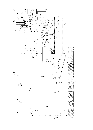
Turning now to Figure 1 of the appended
drawings, an exhaust hood apparatus 10, according to
a first preferred embodiment of the present invention,
will be described.
The exhaust hood apparatus 10 includes a
hood 12, a washing system 14, a sprinkler system 16,
an exhaust duct 18 and a controller circuit 20.
As illustrated in this figure, the hood 12
is adapted to be mounted to a wall 22 over a cooking
station 24 including heating elements 26. Heating
elements 26 may be electrical heating elements, liquid
or gaseous fuel burners, or other types of heating
elements. The heating elements 26 are supplied in
electricity or fuel through a conventional supply
arrangement (not shown).
The washing system 14 includes water
conduits 28 to which is mounted a conventional washing
nozzle 30. A hot water source (see arrow 31) supplies
hot washing water to the water conduits 28 through a
solenoid valve 36 having a control input/status output
38.
As illustrated in Figure 1, the nozzle 30
is mounted in a plenum chamber 101 which prevents the
2 1 6~702
-
water exiting the nozzle 30 to be projected on the
cooking station 24. Furthermore, the internal walls
103 of the plenum chamber 101 collects grease or other
particles contained in the cooking by-products, and a
drain outlet 99 evacuates the water exiting the nozzle
30 as will be explained hereinafter.
The control input/status output 38 of the
solenoid valve 36 is electrically connected to a
control output/status input 44 of the controller
circuit 20 via an electrical cable 46.
The control input/status output 38 allows
the opening and the closing of the solenoid valve 30
by the controller circuit 20 and supplies the status
of the solenoid valve 36 to the controller circuit 20.
The controller circuit 20 may therefore
initiate a washing cycle by opening the solenoid valve
36.
The sprinkler system 16 includes water
conduits 48 to which a conventional sprinkler nozzle
50 is mounted. The water conduits 48 are supplied
with cold water from a conventional sprinkler water
line (see arrow 33) through a pressure sensor 52
2 1 69702
having a data output 54 and a flowmeter 56 having a
data output 58.
The data output 54 of the pressure sensor
52 is electrically connected to a data input 60 of the
controller circuit 20 via an electrical cable 62. The
pressure sensor 52 therefore notifies the controller
circuit 20 should the water pressure of the
conventional sprinkler water line (see arrow 33) be
outside a predetermined pressure range.
Similarly, the data output 58 of the
flowmeter 56 is electrically connected to data input
64 of the controller circuit 20 via an electrical
cable 66. The flowmeter 56 notifies the controller
circuit 20 should the sprinkler system 16 be actuated.
It is to be noted that the water conduits
48 of the sprinkler system 16 are also connected to
the water conduits 28 of the washing system 14 through
a solenoid valve 32 having a control input/status
output 34 which is electrically connected to a control
output/status input 40 of the controller circuit 20
via an electrical cable 42.
The control input/status output 34 allows
the opening and the closing of the solenoid valve 32
- 2 1 69702
by the controller circuit 20 and supplies the status
of the solenoid valve 32 to the controller circuit 20.
It is to be noted that more than one
sprinkler nozzle 50 could be used depending of the
type of cooking station 24 used.
It is also to be noted that the sprinkler
system 16 could be replaced by other types of
conventional chemical fire fighting. These systems
(not shown) often use electrically or mechanically
actuated nozzles to spray the chemical compound on the
fire. As will be easily understood to one of ordinary
skills in the art, these electrical or mechanical
nozzles may be electrically connected to the
controller circuit 20 to thereby warn the controller
circuit 20 should they be actuated.
The exhaust duct 18 includes an exhaust
fan 70 having a control input 72 electrically
connected to a control output 74 of the controller
circuit 20 via an electrical cable 76. The control
input 72 allows the controller circuit 20 to energize
and to de-energized the exhaust fan 70. The exhaust
fan 70 is mounted so as to draw air from the plenum
chamber 101 and to expel this air toward an external
- ` 2 1 6q7U2
14
environment (not shown) when the exhaust fan 70 is
energized.
The hood 12 optionally includes a lighting
system 78 having a control input 80 in electrical
connection with a control output 82 via an electrical
cable 84. The control input 80 allows the opening and
the closing of the lighting system 80 by the
controller circuit 20.
The hood 12 also includes a first
temperature sensor 86 having a temperature output 88
and mounted near the junction of the exhaust duct 18
and the hood 12. The temperature output 88 is in
electrical connection with a temperature input 90 of
the controller circuit 20 via an electrical cable 92.
The controller 20 may therefore monitor the
temperature at the junction of the exhaust duct 18 and
the hood 12.
The hood 12 also includes a second
temperature sensor 94 having a temperature output 96
and mounted to the top portion of the hood 12. The
temperature output 96 is in electrical connection with
a temperature input 98 of the controller circuit 20
via an electrical cable 100. The controller 20 may
therefore monitor the temperature in the hood 12.
2 1 69702
As illustrated in Figure 1, the controller
circuit 20 also includes a control output 102
electrically connected to a control input 104 of the
cooking station 24 via an electrical cable 106. The
control input 104 allows the opening and the closing
of the fuel or electricity supply of the cooking
station 24 by the controller circuit 20.
A hood control panel 108 including an
input/output bus 110 is in electrical connection with
an input/output bus 112 of the controller 20 via an
electrical cable 114.
Figure 3 illustrates a possible embodiment
of the hood control panel 108. However, it is to be
noted that the embodiment of Figure 3 is given as an
example only since many modifications could be done to
the hood control panel 108 without modifying the
principle of operation of the exhaust hood apparatus
of the present invention.
The hood control panel 108 includes a
plurality of indicator lights 116-124 electrically
connected to the controller circuit via the electrical
cable 114. The functions of the indicator lights 116-
124 are as follows:
2 1 69702
16
- light 116 indicates that the exhaust fan
70 is in operation;
- light 118 indicates that the lighting
system 78 is in operation;
- lights 120 indicates that the washing
system 14 is in operation;
- light 122 indicates that the exhaust
hood apparatus 10 is supplied with electricity through
a conventional utility line (not shown); and
- light 124 indicates that a battery
system 126, which will be described hereinafter,
supplies the exhaust hood apparatus 10 with
electricity; when light 124 is energized it implies
that the utility power line (not shown) usually
supplying the hood apparatus 10 with electricity is
offline.
The hood control panel 108 includes an
on/off switch 128 that activates the exhaust fan 70
and an on/off switch 130 that activates the lighting
system 78. Furthermore, a key-activated on/off switch
is provided to prevent the operation of the sprinkler
system 16 should tests be done on other systems of the
exhaust hood 10.
The hood control panel 108 also includes
a plurality of warning lights 132-146 electrically
2 1 6'~702
connected to the controller circuit via the electrical
cable 114. The functions of the warning lights 132-
146 are as follows:
- warning light 132 indicates that the
5 sprinkler system 16 is out of service;
- warning light 134 indicates that the
pressure sensor 52 detects a water pressure outside a
predetermined range;
- warning light 136 indicates that a
problem exists with the internal alimentation power
supply supplying the hood apparatus 10 with
electricity;
- warning light 138 indicates that the
washing system 14 is inoperative;
- warning light 140 indicates that the
controller circuit 20 is malfunctioning;
- warning light 142 indicates that the
electrical connection between at least one temperature
sensor 86 or 9 4 i s malfunctioning;
- warning light 144 indicates that
optional fire extinguishers (not shown) are
malfunctioning; and
- warning light 146 indicates that the
electrical connection between the controller circuit
25 20 and the solenoid valve 56 is malfunctioning.
2 1 6q7u2
18
It is to be noted that other types of
warning means (not shown) such as, for example, a
loudspeaker and/or a blinking light could be used to
replace or to complement the warning lights 132-146.
The hood control panel 108 also includes
an alarm light 148 which indicates that an
uncontrolled fire has been detected by the controller
circuit. For example, it may mean that at least one
of the temperature sensors 86 and 94 has detected a
temperature lying above a predetermined threshold or
that the flowmeter 56 has detected the operation of
the sprinkler system.
It is to be noted that the control panel
108 may be incorporated with the controller circuit 20
in a single unit (not shown).
Returning now to Figure 1, the hood
apparatus 10 also includes a dialling unit 147 having
a control/data input 149 which is electrically
connected to a control/data output 151 of the
controller circuit 20 via an electrical cable 153.
The dialling unit 147 is electrically connected to a
conventional telephone line (see arrow 155). The
controller 20 may therefore dial a predetermined
telephone number and relay a particular message should
2169702
the controller circuit 20 detect a problem with the
hood apparatus 10 or if an uncontrolled fire is
detected. Of course, the controller circuit 20 may
contain a plurality of telephone numbers and a
plurality of messages for particular problems
detected.
As previously mentionned, the exhaust hood
apparatus 10 also includes a battery system 126 having
a power output 150 electrically connected to a power
input 152 of the controller circuit 20 via en
electrical cable 154. The power input (not shown) of
the controller circuit 20 is automatically switched to
the battery system 126 should the controller circuit
20 detect a problem with the utility line (not shown)
supplying electricity to the exhaust hood apparatus
10 .
It is to be noted that the controller
circuit 20 may be electrically connected to various
conventional alarm means represented by light 156 and
loudspeaker 158 in Figure 1. These alarm means are
energized should an uncontrolled fire be detected by
the controller circuit 20. Furthermore, the
controller circuit 20 may also be electrically
connected to a conventional modem 160. If this is the
case, the controller 20 may then be accessed through
216Y702
-
a conventional telephone line (see arrow 161) to
thereby allow the remote modification of the
configuration of the controller circuit 20 and the
remote operation of the hood apparatus 10.
As will be easily understood by someone of
ordinary skills in the art, the various components
electrically connected to the controller circuit 20,
excluding the temperature sensors 86 and 94, the
lighting system 78 and the exhaust fan 70, could be
incorporated in a single control unit (not shown).
It is to be noted that many other safety
devices could be electrically connected to the
controller circuit 20 to detect various potentially
dangerous situations and allow the controller circuit
20 to react to these situations by emitting warning
signals or entering the fire suppression mode. As non
limitative examples, smoke sensors, gas leak sensors
and/or electrical overloads sensors could be
electrically connected to the controller circuit 20.
In operation, switches 128 and 130 are
used to respectively energize/stop the exhaust fan 70
and the lighting system 78 when these systems are
required in the routine operation of the cooking
station 24.
2 1 69702
-
The controller circuit 20 is configured so
as to activate the washing system 14, by opening the
solenoid valve 36, and therefore initiate a washing
cycle at predetermined and programmable intervals. It
is believed to be within the reach of one of ordinary
skills in the art to determine the duration and
frequency of the wash cycles as well as the
temperature of the water and the type of detergent
used, if any.
If, at any time, (a) one of the
temperature sensors 86 and 94 detects a temperature
that lies above a predetermined threshold temperature
(which may be different for sensor 86 and sensor 94),
or (b) the flowmeter 56 detects the operation of the
sprinkler system 16, this information is supplied to
the controller circuit 20 which enters a fire
suppression mode.
When the controller circuit 20 enters in
the fire suppression mode, two major systems are
activated by the controller circuit 20: the washing
system 14, by opening the solenoid valve 32, and the
exhaust fan 70.
The washing system 14 therefore sprays
cold water through its washing nozzle 30, and the
2 1 69702
exhaust fan draws air from the hood 12 through the
plenum chamber 101 and exhaust it through the exhaust
duct 18.
5Part of the small drops of cold water
exiting the washing nozzle 30 is drawn in the exhaust
duct 18 by the exhaust fan 70. Therefore, the water
drawn in the exhaust duct 18 cools the exhaust duct
18. The temperature of the air entering the exhaust
10duct 18 from the plenum chamber 101 is therefore
maintained below the above discussed flash point,
which prevents the propagation of fire through the
exhaust duct 18.
15Of course, if the sprinkler system is
operating to extinguish the uncontrolled fire, part of
the small drops of cold water exiting the sprinkler
nozzle 50 is drawn in the exhaust duct 18, through the
plenum chamber 101, by the exhaust fan 70, again
cooling the exhaust duct 18.
The controller circuit 20 may also
initiate several other actions when it enters the fire
suppression mode. For example, it may sound an
audible alarm through the speaker 158, it may use the
dialling unit 147 to contact the fire station, it may
close the lighting system 78 to prevent electrical
2 1 SY7U2
23
fire hazards and it may close the fuel or electrical
supply of the cooking station 24.
As will be easily understood by one of
ordinary skills in the art, the battery system 126
will supply the exhaust hood apparatus 10 with
electricity should the utility power line (not shown)
fail during a fire.
It is to be noted that the controller
circuit 20 may be formed by one or a plurality of
electronic circuits (not shown) which may include one
or a plurality of microprocessors, micro-controllers
and/or programmable automaton and their associated
hardware and software. It is believed to be within
the skills of one of ordinary skills in the art of
electronics to select the components of the controller
circuit 20 and to configure them so as to perform the
above-mentioned operations.
Turning now to Figure 2 of the appended
drawings, an exhaust hood apparatus 200 according to
a second embodiment of the present invention will be
described.
Two major differences exist between the
exhaust hood apparatus 10 of Figure 1 and the exhaust
21 69702
24
hood apparatus 200 of Figure 2. First, the exhaust
hood 200 is adapted to be mounted to a ceiling (not
shown) while exhaust hood apparatus 10 is adapted to
be mounted to a wall 22. Therefore, since the exhaust
duct 18 and the plenum chamber 101 of the hood
apparatus 200 are centered, some of the systems are
present on both sides of the plenum chamber 101. For
example, the lighting systems 78a, 78b, the
temperature sensors 94a, 94b and the sprinkler nozzles
50a, 50b. Of course, these systems operate as
previously described with respect to Figure 1.
The second major difference is the fact
that the exhaust hood apparatus 200 includes two air
intake ducts 202 and 204. These ductæ allow the air
to come from the external environment to the exhaust
hood 212 to therefore create what is generally known
in the art as an air curtain.
Conventional intake ducts 202 and 204 are
respectively provided with damper assemblies 206 and
208 which are pivotally mounted to pins 214 and 216,
respectively. These damper assemblies 206 and 208
include biasing means (not shown) biasing the dampers
206 and 208 towards a position where the intake ducts
202 and 204, respectively, are closed (see direction
arrows 230 and 232). However, lines 218 and 220
- 21 69702
respectively maintain the damper assemblies 206 and
208 in an opened position. Heat fuses 222 and 224
mechanically severe the lines 218 and 220 if a
predetermined temperature is reached near the heat
S fuses 222 and 224, thereby closing the dampers 206 and
208 to prevent fire propagation through the intake
ducts 202 and 204.
It is to be noted that the damper
assemblies 206 and 208 are in electrical connection
with the controller circuit 20 via electrical cables
226 and 228, respectively. Therefore, the controller
circuit 20 is notified if the air intake ducts 202 and
204 are closed and it may enter the fire suppression
15 mode. This characteristic increases the reliability
of the exhaust hood apparatus 200 since it further
provides a third mechanism of fire detection. Of
course, the first and second mechanisms of fire
detection are the temperature sensors 86 and 94, and
20 the sprinkler system 16 and its associated flowmeter
56.
Of course, the control panel 108 of the
hood apparatus 200 may include status lights (not
shown) which are energized if the dampers 202 and 204
are closed, and warning lights (not shown) which are
energized should the electrical connection between the
2 1 6 Y702
dampers and the controller circuit 20 experience
problems.
The other characteristics and elements of
the exhaust hood apparatus 200 are similar to the
characteristics and elements of the exhaust hood
apparatus 10 described hereinabove and therefore will
not be repeated herein.
It is to be noted that solenoid valves 32
and 36 could be replaced by any type of valve that may
be remotely opened and closed by the controller
circuit 20.
The above described exhaust hood
apparatuses 10 and 200 have several advantages. For
example:
- the configuration of the controller
circuit 20 may easily be changed to suit the needs of
the owner;
- at least a portion of the smoke
generated by the uncontrolled fire is exhausted
through the exhaust duct 18;
- the exhaust duct 18 is maintained below
the flash point without the need of dampers or
conduits along its entire length;
-- 2~69~U2
- the battery systems 126 maintains the
hood in operation even if the utility power is out;
and
- the dialling unit 147 may automatically
contact the fire department when a fire condition
occurs.
Although the present invention has been
described hereinabove by way of preferred embodiments
thereof, it can be modified; without departing from
the spirit and nature of the subject invention as
defined in the appended claims.